EP0698723A2 - Circuit de refroidissement fermé pour aube distributeur de turbine - Google Patents
Circuit de refroidissement fermé pour aube distributeur de turbine Download PDFInfo
- Publication number
- EP0698723A2 EP0698723A2 EP95304883A EP95304883A EP0698723A2 EP 0698723 A2 EP0698723 A2 EP 0698723A2 EP 95304883 A EP95304883 A EP 95304883A EP 95304883 A EP95304883 A EP 95304883A EP 0698723 A2 EP0698723 A2 EP 0698723A2
- Authority
- EP
- European Patent Office
- Prior art keywords
- vane
- wall
- cooling medium
- impingement
- compartments
- Prior art date
- Legal status (The legal status is an assumption and is not a legal conclusion. Google has not performed a legal analysis and makes no representation as to the accuracy of the status listed.)
- Withdrawn
Links
- 238000001816 cooling Methods 0.000 title claims abstract description 65
- 239000002826 coolant Substances 0.000 claims description 81
- 238000004891 communication Methods 0.000 claims description 25
- 238000005266 casting Methods 0.000 claims description 3
- 238000010025 steaming Methods 0.000 abstract 1
- 239000007789 gas Substances 0.000 description 11
- 230000004907 flux Effects 0.000 description 3
- 238000007789 sealing Methods 0.000 description 3
- 125000006850 spacer group Chemical group 0.000 description 3
- 238000002485 combustion reaction Methods 0.000 description 2
- 238000003466 welding Methods 0.000 description 2
- 241000725175 Caladium bicolor Species 0.000 description 1
- 241000196324 Embryophyta Species 0.000 description 1
- 235000015966 Pleurocybella porrigens Nutrition 0.000 description 1
- 238000013459 approach Methods 0.000 description 1
- 238000005219 brazing Methods 0.000 description 1
- 239000000567 combustion gas Substances 0.000 description 1
- 238000000605 extraction Methods 0.000 description 1
- 238000004519 manufacturing process Methods 0.000 description 1
- 239000000463 material Substances 0.000 description 1
- 238000002844 melting Methods 0.000 description 1
- 230000008018 melting Effects 0.000 description 1
- 239000002184 metal Substances 0.000 description 1
- 238000012986 modification Methods 0.000 description 1
- 230000004048 modification Effects 0.000 description 1
- 230000003071 parasitic effect Effects 0.000 description 1
- 230000002093 peripheral effect Effects 0.000 description 1
- 238000005086 pumping Methods 0.000 description 1
- 238000012552 review Methods 0.000 description 1
Images




Classifications
-
- F—MECHANICAL ENGINEERING; LIGHTING; HEATING; WEAPONS; BLASTING
- F01—MACHINES OR ENGINES IN GENERAL; ENGINE PLANTS IN GENERAL; STEAM ENGINES
- F01D—NON-POSITIVE DISPLACEMENT MACHINES OR ENGINES, e.g. STEAM TURBINES
- F01D5/00—Blades; Blade-carrying members; Heating, heat-insulating, cooling or antivibration means on the blades or the members
- F01D5/12—Blades
- F01D5/14—Form or construction
- F01D5/18—Hollow blades, i.e. blades with cooling or heating channels or cavities; Heating, heat-insulating or cooling means on blades
- F01D5/187—Convection cooling
- F01D5/188—Convection cooling with an insert in the blade cavity to guide the cooling fluid, e.g. forming a separation wall
- F01D5/189—Convection cooling with an insert in the blade cavity to guide the cooling fluid, e.g. forming a separation wall the insert having a tubular cross-section, e.g. airfoil shape
-
- F—MECHANICAL ENGINEERING; LIGHTING; HEATING; WEAPONS; BLASTING
- F01—MACHINES OR ENGINES IN GENERAL; ENGINE PLANTS IN GENERAL; STEAM ENGINES
- F01D—NON-POSITIVE DISPLACEMENT MACHINES OR ENGINES, e.g. STEAM TURBINES
- F01D5/00—Blades; Blade-carrying members; Heating, heat-insulating, cooling or antivibration means on the blades or the members
-
- F—MECHANICAL ENGINEERING; LIGHTING; HEATING; WEAPONS; BLASTING
- F01—MACHINES OR ENGINES IN GENERAL; ENGINE PLANTS IN GENERAL; STEAM ENGINES
- F01D—NON-POSITIVE DISPLACEMENT MACHINES OR ENGINES, e.g. STEAM TURBINES
- F01D11/00—Preventing or minimising internal leakage of working-fluid, e.g. between stages
- F01D11/005—Sealing means between non relatively rotating elements
-
- F—MECHANICAL ENGINEERING; LIGHTING; HEATING; WEAPONS; BLASTING
- F01—MACHINES OR ENGINES IN GENERAL; ENGINE PLANTS IN GENERAL; STEAM ENGINES
- F01D—NON-POSITIVE DISPLACEMENT MACHINES OR ENGINES, e.g. STEAM TURBINES
- F01D5/00—Blades; Blade-carrying members; Heating, heat-insulating, cooling or antivibration means on the blades or the members
- F01D5/12—Blades
- F01D5/14—Form or construction
- F01D5/18—Hollow blades, i.e. blades with cooling or heating channels or cavities; Heating, heat-insulating or cooling means on blades
- F01D5/187—Convection cooling
-
- F—MECHANICAL ENGINEERING; LIGHTING; HEATING; WEAPONS; BLASTING
- F01—MACHINES OR ENGINES IN GENERAL; ENGINE PLANTS IN GENERAL; STEAM ENGINES
- F01D—NON-POSITIVE DISPLACEMENT MACHINES OR ENGINES, e.g. STEAM TURBINES
- F01D5/00—Blades; Blade-carrying members; Heating, heat-insulating, cooling or antivibration means on the blades or the members
- F01D5/12—Blades
- F01D5/14—Form or construction
- F01D5/18—Hollow blades, i.e. blades with cooling or heating channels or cavities; Heating, heat-insulating or cooling means on blades
- F01D5/187—Convection cooling
- F01D5/188—Convection cooling with an insert in the blade cavity to guide the cooling fluid, e.g. forming a separation wall
-
- F—MECHANICAL ENGINEERING; LIGHTING; HEATING; WEAPONS; BLASTING
- F05—INDEXING SCHEMES RELATING TO ENGINES OR PUMPS IN VARIOUS SUBCLASSES OF CLASSES F01-F04
- F05D—INDEXING SCHEME FOR ASPECTS RELATING TO NON-POSITIVE-DISPLACEMENT MACHINES OR ENGINES, GAS-TURBINES OR JET-PROPULSION PLANTS
- F05D2240/00—Components
- F05D2240/10—Stators
-
- F—MECHANICAL ENGINEERING; LIGHTING; HEATING; WEAPONS; BLASTING
- F05—INDEXING SCHEMES RELATING TO ENGINES OR PUMPS IN VARIOUS SUBCLASSES OF CLASSES F01-F04
- F05D—INDEXING SCHEME FOR ASPECTS RELATING TO NON-POSITIVE-DISPLACEMENT MACHINES OR ENGINES, GAS-TURBINES OR JET-PROPULSION PLANTS
- F05D2240/00—Components
- F05D2240/80—Platforms for stationary or moving blades
- F05D2240/81—Cooled platforms
-
- F—MECHANICAL ENGINEERING; LIGHTING; HEATING; WEAPONS; BLASTING
- F05—INDEXING SCHEMES RELATING TO ENGINES OR PUMPS IN VARIOUS SUBCLASSES OF CLASSES F01-F04
- F05D—INDEXING SCHEME FOR ASPECTS RELATING TO NON-POSITIVE-DISPLACEMENT MACHINES OR ENGINES, GAS-TURBINES OR JET-PROPULSION PLANTS
- F05D2260/00—Function
- F05D2260/20—Heat transfer, e.g. cooling
- F05D2260/201—Heat transfer, e.g. cooling by impingement of a fluid
-
- F—MECHANICAL ENGINEERING; LIGHTING; HEATING; WEAPONS; BLASTING
- F05—INDEXING SCHEMES RELATING TO ENGINES OR PUMPS IN VARIOUS SUBCLASSES OF CLASSES F01-F04
- F05D—INDEXING SCHEME FOR ASPECTS RELATING TO NON-POSITIVE-DISPLACEMENT MACHINES OR ENGINES, GAS-TURBINES OR JET-PROPULSION PLANTS
- F05D2260/00—Function
- F05D2260/20—Heat transfer, e.g. cooling
- F05D2260/221—Improvement of heat transfer
- F05D2260/2212—Improvement of heat transfer by creating turbulence
-
- F—MECHANICAL ENGINEERING; LIGHTING; HEATING; WEAPONS; BLASTING
- F05—INDEXING SCHEMES RELATING TO ENGINES OR PUMPS IN VARIOUS SUBCLASSES OF CLASSES F01-F04
- F05D—INDEXING SCHEME FOR ASPECTS RELATING TO NON-POSITIVE-DISPLACEMENT MACHINES OR ENGINES, GAS-TURBINES OR JET-PROPULSION PLANTS
- F05D2260/00—Function
- F05D2260/20—Heat transfer, e.g. cooling
- F05D2260/232—Heat transfer, e.g. cooling characterized by the cooling medium
- F05D2260/2322—Heat transfer, e.g. cooling characterized by the cooling medium steam
-
- Y—GENERAL TAGGING OF NEW TECHNOLOGICAL DEVELOPMENTS; GENERAL TAGGING OF CROSS-SECTIONAL TECHNOLOGIES SPANNING OVER SEVERAL SECTIONS OF THE IPC; TECHNICAL SUBJECTS COVERED BY FORMER USPC CROSS-REFERENCE ART COLLECTIONS [XRACs] AND DIGESTS
- Y02—TECHNOLOGIES OR APPLICATIONS FOR MITIGATION OR ADAPTATION AGAINST CLIMATE CHANGE
- Y02T—CLIMATE CHANGE MITIGATION TECHNOLOGIES RELATED TO TRANSPORTATION
- Y02T50/00—Aeronautics or air transport
- Y02T50/60—Efficient propulsion technologies, e.g. for aircraft
Definitions
- the present invention relates to a stator vane segment for use as part of a stage of a turbine, and particularly relates to a stator vane segment having integrally cast side walls and vanes for use under high thermal fluxes and high internal pressures, as well as a closed cooling circuit.
- the traditional approach for cooling turbine blades and nozzles is to extract high pressure cooling air from a source, for example, by extracting air from the intermediate and last stages of the turbine compressor.
- a series of internal flow passages are typically used to achieve the desired mass flow objectives for cooling the turbine blades.
- external piping is used to supply air to the nozzles with air film cooling typically being used.
- the diverted coolant air does not receive energy directly from the combustors of the turbine and represents a parasitic loss to turbine output and degrades overall performance.
- Thin walls, desirable for cooling purposes, may not be sufficient to withstand the pressure difference without incurring excessive mechanical stresses. That is, the necessary thickness to maintain structural integrity would drastically increase the magnitude of the required cooling flow.
- stator vane segments which can be cooled while operating under high thermal fluxes and high pressures.
- stator vane segments having the necessary structural integrity under high thermal fluxes and pressures, while simultaneously affording inner and outer walls capable of being cooled by a cooling medium, preferably steam, flowing in a closed circuit.
- a cooling medium preferably steam
- the present invention provides a plurality of stator vane segments each of which comprise one or more stator vanes extending between outer and inner side walls.
- the vanes have a plurality of cavities in communication with compartments in the outer and inner side walls for flowing a cooling media, preferably steam, in a closed-circuit path for cooling the outer and inner walls and the vanes.
- the outer and inner side walls, the vanes, and one or more hooks on the outer side wall are integrally formed, preferably by casting, to provide the structural strength necessary to support the plural stator vane segments as part of the stage of the turbine.
- These hooks which form the connection between the inner shell of the turbine and provide the support for the stator vane segments, are integrally and structurally connected with the vanes and spaced outwardly of the outer side wall, enabling reduced material thicknesses for the walls per se .
- the outer side wall has a plurality of ribs extending along an outer surface of the wall defining a plurality of compartments outwardly of the outer surface.
- the ribs are undercut or provided with openings for communicating a cooling media, e.g., steam, from an inlet to the segment into the compartments.
- Impingement plates are disposed in each compartment defining inner and outer chambers.
- the cooling media is inlet to the outer chambers through the undercuts or openings in the ribs for flow through a plurality of openings in the impingement plates for impingement cooling flow against the outer surface of the outer side wall.
- the compartments lie in communication with one or more of cavities extending internally within the vanes for flowing the cooling medium into the vanes.
- the inner side wall is similarly compartmentalized by at least one rib and also includes impingement plates in the compartments defining inner and outer chambers.
- the cavities of the vane have outlets in communication with the inner chambers of the inner side wall whereby cooling medium flows through the openings of impingement plates into the outer chamber of the inner compartments for impingement cooling of the inner side wall.
- the vanes include exit openings in communication with the outer chambers of the inner side wall for flowing the cooling media through a return cavity within the vanes for flow through an exhaust port outwardly of the outer side wall.
- Impingement cooling of the vanes is also provided.
- inserts are provided the majority of the cavities of the vane.
- an insert is provided the cavity adjacent the leading edge of the vane and includes a sleeve having at its outer end openings in communication with the inner chambers of the compartments and the outer side wall for flowing cooling medium into the insert sleeve.
- the interior walls of the cavities have a plurality of inwardly projecting ribs at spaced locations lengthwise therealong. In each such cavity, these ribs define with the insert sleeve a plurality of spaced gaps between the insert and the interior wall.
- the insert sleeve has a plurality of openings for flowing cooling medium from within the insert sleeve through the openings for impingement cooling against the inner surface of the vane in each gap.
- the cooling medium flows to a return channel formed between a portion of the insert sleeve and an interior wall of the cavity for flow into the inner chambers of the inner side wall.
- the outer chambers of the inner side wall have openings communicating the cooling medium into a second or return cavity within the vane.
- the return cavity similarly has an insert sleeve with openings for flowing the returning cooling medium through the openings for impingement cooling of the return cavity.
- the return cavity likewise has ribs projecting from its inner wall surface, defining gaps whereby the cooling medium flows into the gaps and into a return channel between the insert and the cavity wall.
- the returning cooling medium is returned to a plenum outside of the outer side wall for exhaust.
- an air circuit is provided for cooling one of the cavities, preferably the last cavity adjacent the trailing edge of the vane.
- air is inlet through suitable inlet ports in the outer side wall for cooling flow through the trailing edge cavity and directly into a plenum inwardly of the inner side wall.
- a plurality of openings are provided through the forward and aft surfaces of the diaphragm whereby the cooling air flows into the wheel cavities of the turbine for cooling purposes and also to prevent leakage of hot gases of combustion into the wheel space.
- a stator vane segment for forming part of a stage of a turbine and connection with an inner shell of the turbine, comprising inner and outer walls spaced from one another, a stator vane extending between the inner and outer walls and having leading and trailing edges, the vane including a plurality of discrete cavities between the leading and trailing edges and extending lengthwise of the vane for flowing a cooling medium and a hook connected to the vane and projecting outwardly of the outer wall for supporting the stator vane from the inner turbine shell, the inner and outer walls, the vane and the hook being formed of an integral casting.
- a stator vane segment for forming part of a stage of a turbine and connection with an inner shell of the turbine, comprising inner and outer walls spaced from one another, a stator vane extending between the inner and outer walls and having leading and trailing edges, the vane including a plurality of discrete cavities between the leading and trailing edges and extending lengthwise of the vane for flowing a cooling medium, the outer wall having a plurality of ribs along an outer surface thereof defining a plurality of compartments outwardly of the outer surface for receiving the cooling medium and forming structural connections with the vane, a cover for each compartment, impingement plates in the compartments between the covers and the outer surface defining outer and inner chambers on opposite sides of the impingement plates and in the compartments, a cooling medium inlet for the segment, the ribs having openings for enabling passage of the cooling medium from the inlet into the outer chambers of the compartments, the impingement plates having openings enabling passage
- a stator vane segment for forming part of a stage of a turbine and connection with an inner shell of the turbine, comprising inner and outer walls spaced from one another, a stator vane extending between the inner and outer walls and having leading and trailing edges, the vane including a plurality of discrete cavities between the leading and trailing edges and extending lengthwise of the vane for flowing a cooling medium, the inner wall having a plurality of ribs along an inner surface thereof defining a plurality of compartments inwardly of the inner surface for receiving the cooling medium and forming structural connections with the vane, a cover for one of the compartments, an impingement plate in one compartment between the cover and the inner surface defining inner and outer chambers on opposite sides of the impingement plate and in the one compartment, the vane having an opening through a side wall thereof in communication with the inner chamber and one of the cavities for flowing the cooling medium between the one cavity and the inner chamber, the impingement plate having openings
- a stator vane segment for forming part of a stage of a turbine and connection with an inner shell of the turbine, comprising inner and outer walls spaced from one another, a stator vane extending between the inner and outer walls and having leading and trailing edges, the vane including a plurality of discrete cavities between the leading and trailing edges and extending lengthwise of the vane for flowing a cooling medium, at least one cavity of the vane having a plurality of ribs projecting inwardly of an inner wall surface of the vane at spaced locations along the length of the vane, an insert sleeve within the one cavity and engaging the ribs defining discrete gaps between the insert sleeve and the inner wall of the vane at spaced locations along the vane, an inlet to the insert sleeve for flowing the cooling medium into the insert sleeve, the insert sleeve having a plurality of openings therethrough for flowing the cooling medium through the s
- turbine 10 having an inner shell 12 surrounding the various stages of the turbine.
- turbine 10 includes a first stage nozzle 14, a first stage of turbine buckets 16, a second stage nozzle 18 and a second stage of turbine buckets 20.
- the buckets 16 and 20 respectively are mounted on pedestals 22 and 24 which in turn are mounted on turbine wheels, not shown, for rotation about the turbine axis.
- Spacers 26 are disposed axially between and secured to the wheels of the turbine for rotation therewith and include a sealing surface 28 for sealing against the interface of a fixed diaphragm 30.
- the second stage nozzle 18 includes a plurality of radially extending vanes 32 circumferentially spaced one from the other and extending generally radially inwardly from an outer side wall 34 to an inner side wall 36 to which the diaphragm 30 is secured. It will be appreciated that hot gases of combustion from the turbine combustors, not shown, flow generally axially, for example, from left to right in Figure 1 through the first stage nozzles 14 for driving the first stage of turbine buckets 16 and which gas then flows through the fixed second stage 18 for driving the second stage of turbine buckets 20.
- FIG. 2 there is illustrated a second stage stator vane segment generally designated 38, each segment including outer and inner side walls 34 and 36 respectively with one or more stator vanes 32 extending between the outer and inner side walls.
- the segments 38 are spaced circumferentially one from the other about the inner shell of the turbine and are supported from the inner shell.
- the adjoining segments are sealed one to the other by leaf type seals 40 ( Figure 5) situated in grooves 42 formed along the side edges of each of the outer and inner side walls 34 and 36 respectively.
- leaf type seals 40 Figure 5
- the outer and inner side walls as well as the vanes and diaphragms are wholly supported by the inner shell of the turbine.
- one or more supporting hooks 44 are integrally cast with a corresponding vane in each segment as well as integrally cast with the outer and inner side walls 34 and 36 respectively to provide the necessary structural support.
- An aft supporting hook 46 is formed on the aft side of the outer side wall 34.
- a cooling medium inlet port 48 for supplying cooling medium, preferably steam, to the outer and inner side walls and the vanes of the segment.
- a return cooling medium plenum 50 is disposed adjacent the upper ends of the vanes 32 for receiving the spent cooling medium for exhaust through a discharge 52.
- a pair of air inlets 54 are also disclosed for flowing air into the vanes along the trailing edges thereof for exiting into the diaphragm 30 and into the wheel cavities as described hereinafter.
- each segment preferably comprises a pair of vanes between outer and inner side walls 34 and 36 respectively although it will be appreciated that a fewer or greater number of vanes can be employed in each segment as desired.
- each segment 38 includes outer railings 52 projecting outwardly along the outer margins of outer side wall 34. (The terms outwardly and inwardly or outer and inner refer to a generally radial direction.)
- the railings 52 define the marginal edges of the segment 38 with the exception that the aft hook 46 forms the outer margin along the aft side of the segment.
- Each railing 52 has an inner platform or flange 53.
- a mid-segment rib 56 extends from the leading railing 52 to the aft hook 46 and between the vanes 32 which project through the outer side wall 34.
- internal railings 58, 60, 62, 64, 66 and 67 are integrally cast with the vanes and the inner and outer side walls as well as the hooks.
- the internal railings 58, 62, 64 and 66 extend from the side railing and mid-rib for connection with the outer ends of the vanes while the railing 60 extends from the outer railing 52 to the vane and railing 67 extends from arcuate wall 86 to the vane.
- these railings divide the back side of the outer wall 34 into a plurality of compartments 68a-68f, for example, the compartment 68c defined between internal railings 60 and 62 and outer railing 52.
- Each of the internal railings is either undercut, for example, at 70 or provided with an opening therethrough, for example, at 72 whereby the various compartments defined by the internal railings lie in communication one with the other.
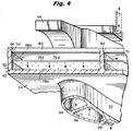
- Each compartment 68a-68f is provided with a perforated impingement plate 74a-74f, respectively, which divides the compartment into outer and inner chambers 76, 78, for example, the outer and inner chambers 76d and 78d separated by impingement plate 74d as illustrated in Figure 4.
- a plurality of cover plates are provided for the compartments 68.
- Each cover plate 80 is provided with openings or slots 82 for receiving correspondingly located portions of the internal railings to locate the cover in overlying position relative to the compartments and to the flange 53.
- the covers 80 are beveled along their edges 84 to permit TIG welding onto the segment.
- a cooling medium preferably steam
- a cooling medium flows into a plenum defined by the aft hook 46 and an arcuate wall 86 ( Figure 3) for flow through openings 88 into the outer chambers 76 of compartments 68.
- the cooling medium flows into the outer chambers 76 through the undercuts or openings in the internal railings and then passes through perforations in the impingement plates 74 into inner chambers 78 of compartments 68 for impingement cooling of the outer wall 34 as illustrated in Figure 4.
- each vane 32 has a plurality of internal cavities, preferably five cavities 94, 96, 98, 100 and 102.
- steam is supplied through the forward and intermediate cavities 94 and 98 to the inner side wall 36 and returns to the outer side wall through an intermediate cavity 96.
- openings 104 and ( Figure 3) 106 lie in communication with adjacent inner chambers 78 of the compartments.
- the inner side wall 36 has a plurality of inwardly directed side railings 110 as well as interior railings 112, 114, 116 and 118 defining along the inner side wall a plurality of compartments 120a, 120b, 120c and 120d.
- the compartments are also defined in part by inner covers 123 secured, preferably by welding, to the side and interior railings of the inner side wall 36.
- Impingement plates 121 are disposed in each compartment dividing the compartments into inner chambers 122a, 122b, 122c and 122d and outer chambers 124a, 124b, 124c and 124d.
- each of the cavities 94 and 98 has a pair of openings 126a, 126b and 128c, 128d, respectively, for flowing the cooling medium into the inner chambers 122a, 122b and 122c, 122d, respectively, of the inner compartments 120 of the inner side wall 36.
- the flow of cooling medium into the inner chambers 122 enables the flow to pass generally radially outwardly through the perforations in the impingement plates 121 into the outer chambers 124a, 124b, 124c and 124d for impingement cooling of the inner side wall 36.
- the outer chambers 124a, 124b, 124c and 124d communicate with the return cavity 96 of vane 32 by way of openings 130a, 130b, 130c and 130d, respectively.
- Return cavity 96 communicates with the plenum 50 ( Figure 2) for exhausting the spent cooling medium through the discharge 52.
- cooling air passes through inlets 54 directly into the aft cavities 100 and 102 of each vane 32.
- the cavities 100 and 102 exhaust the cooling air through the inner side wall 36 and the covers 123 into the diaphragm 30.
- the covers 123, the side walls and inner wall 140 of the diaphragm 30 define a plenum 141. Adjacent each of the forward and aft sides of the plenum are apertures 142 and 144 respectively for flowing the extraction air into the wheel spaces on axially opposite sides of the diaphragm. It is also possible to use pipe connections with nozzles between exhausts of cavities 100 and 102 to accelerate air flow toward apertures 142 and 144.
- the openings are formed such that they provide a tangential air flow into the wheel space cavities.
- Seals 146 and 148 are formed along the forward and aft sides of the diaphragm for sealing with the adjacent angel wings of the turbine wheels. The pumping action of the turbine rotor forces the air flow to proceed around the seals 146 and 148. Because there is a substantial pressure difference between the forward and aft sides of the diaphragms, a portion of the cooling air will flow below the diaphragm between it and the spacers 26.
- a metallic honeycomb 149 is provided along the inner side of diaphragm 30. The honeycomb seals are brazed directly onto the bottom of the diaphragm.
- the spacer which rotates has a plurality of labyrinthine knife edges for extending into the honeycomb seal for reducing the air leakage.
- the leading edge cavity 94 is provided with an insert 160 and which insert 160 is provided in three different sections to facilitate manufacture.
- An outer section 162 is used to locate and position the insert 160 within the vane.
- the outer section 162 includes a collar 164 which is secured, for example, by brazing to an intermediate section 166.
- Collar 164 rests on a flange formed in the upper end of the vane.
- Intermediate section 166 includes a plurality of openings 168 which lie in communication with the openings 104 of the inner chambers of the compartments 68b-68f.
- post-impingement cooling medium from the inner chamber 78 of outer side wall 34 passes through openings 104 and openings 168 of the insert 160 for flow inwardly through the lower section 170.
- the intermediate section 166 is secured to the vane 32 inwardly of the openings 104 such that flow of the cooling medium from the inner chambers through openings 104 must pass through openings 168 and cannot pass between intermediate section 166 and the inner wall of the vane.
- the intermediate section 166 may be brazed to the inner wall of the vane.
- ribs 172 there is provided at radially spaced locations along the vane a plurality of inwardly directed projections or ribs 172 for spacing the lower section 170 of insert 160 from the inner surfaces of the walls of the vane.
- the lower section 170 has a plurality of impingement flow openings 174 such that the cooling medium flowing inwardly along the lower section 170 of insert 160 passes through openings 174 for impingement cooling against the interior surfaces of vane 32 between the ribs 172.
- ribs 172 do not extend wholly about the interior of cavity 94. Rather, ribs 172 extend about the interior surfaces of the exterior walls of the cavity and terminate at 180 adjacent the interior dividing wall 181 between the cavities.
- insert section 170 is recessed to define a channel 182 in communication with each of the gaps 184 formed between the insert section 170 and the interior wall of the vane. As illustrated in Figure 6, the bottom of the flow passage within insert section 170 is closed whereby the cooling medium flowing in channel 182 is directed through the openings 126a and 126b ( Figures 5 and 5A) into the inner chambers 122a and 122b of the inner side wall 36.
- insert 191 is provided in vane cavity 98.
- the peripheral outline of insert 191 follows the contour of the shape of cavity 98 and has a plurality of radially spaced inwardly directed structural ribs 190 which terminate at ends 192 and define gaps between insert 191 and the interior wall of cavity 98.
- a channel 194 is formed in and along the forward side of the insert.
- the insert has impingement openings whereby cooling medium directed into the insert through openings 106 ( Figure 3) flows outwardly through the impingement openings for impingement cooling of the outer walls of the vanes on opposite sides of the cavity 98.
- the post-impingement cooling medium then flows generally forwardly along ribs 190 into channel 194 for flow toward the inner side wall 36.
- the post-impingement cooling medium from cavity 98 flows through openings 128c, 128d into the inner chambers 122c, 122d, respectively, of the inner side wall 36 for flow through the perforations of the impingement plates 121 in compartments 120c, 120d for impingement cooling of the inner side wall 36 before returning through openings 130c, 130d, respectively, to intermediate cavity 96.
- Intermediate cavity 96 similarly has a double insert 210 having a plurality of perforations or openings 212.
- Ribs 214 spaced radially along the walls of cavity 96 project inwardly toward insert 210 and terminate at opposite ends of the cavity to define a pair of channels 216 at opposite ends of the cavity.
- the cooling medium thus flows radially outwardly within insert 210, through the impingement perforations for impingement cooling of the walls of the cavity 96 and into chambers 216 ( Figure 7).
- the spent cooling medium then egresses chambers 216 of cavity 96 into plenum 50 for flow through discharge 52.
- the cooling medium preferably steam
- the cooling steam flows into the outer chambers 76 of the outer side wall 34 by way of openings 88, 72 and undercuts 70.
- the steam flows radially inwardly through the perforations in the impingement plates 74 for egress into the inner chambers 78 and impingement cooling of outer side wall 34.
- the post-impingement cooling steam flows through openings 104 and 106 for flow into the inserts 160 and 191 in the forward and intermediate cavities 94 and 98, respectively.
- the cooling steam flows through the impingement perforations in the inserts and into the gaps between the ribs 172, 190 along the interior surfaces defining the vane cavities for impingement cooling of those surfaces.
- the post-impingement steam then flows into the channels 182 and 194 along the interior walls of the cavities 94 and 98, respectively.
- the post-impingement steam from channels 182 and 194 then flows into the inner chambers 122a, 122b and 122c, 122d, respectively, of the inner side wall 36 by way of openings 126a, 126b and 128c, 128d.
- the steam reverses direction and flows outwardly through the perforations in the impingement plates 121 of compartments 120a, 120b, 120c and 120d into the outer chambers 124a, 124b, 124c and 124d of the inner side wall 36 for impingement cooling thereof.
- the post-impingement steam then flows through openings 130a, 130b, 130c and 130d in the vane and into the insert 210 in the intermediate cavity 96.
- the spent steam then flows through perforations 212 in the insert 210 for impingement cooling of the opposite side walls of the cavity 96 ( Figure 7), the post-impingement steam flowing into the channels 216 for return to the plenum 50 for exhaust through discharge 52.
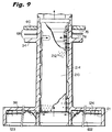
- the air cooling circuit includes air input through inlets 54 into the cavities 100 and 102 for cooling the trailing edge of the vane. As illustrated in Figure 10, the cavities lie in communication one with the other by way of openings 230. The air exits into the plenum 140 of the diaphragm 30 for exit through openings 142 and 144 at the leading and trailing ends of the diaphragm and into the wheel cavities.
Landscapes
- Engineering & Computer Science (AREA)
- Mechanical Engineering (AREA)
- General Engineering & Computer Science (AREA)
- Turbine Rotor Nozzle Sealing (AREA)
Applications Claiming Priority (2)
| Application Number | Priority Date | Filing Date | Title |
|---|---|---|---|
| US29467194A | 1994-08-23 | 1994-08-23 | |
| US294671 | 1994-08-23 |
Publications (2)
| Publication Number | Publication Date |
|---|---|
| EP0698723A2 true EP0698723A2 (fr) | 1996-02-28 |
| EP0698723A3 EP0698723A3 (fr) | 1996-11-13 |
Family
ID=23134425
Family Applications (1)
| Application Number | Title | Priority Date | Filing Date |
|---|---|---|---|
| EP95304883A Withdrawn EP0698723A3 (fr) | 1994-08-23 | 1995-07-13 | Circuit de refroidissement fermé pour aube distributeur de turbine |
Country Status (5)
| Country | Link |
|---|---|
| US (2) | US5634766A (fr) |
| EP (1) | EP0698723A3 (fr) |
| JP (1) | JPH08177406A (fr) |
| KR (1) | KR960007996A (fr) |
| CA (1) | CA2155376A1 (fr) |
Cited By (15)
| Publication number | Priority date | Publication date | Assignee | Title |
|---|---|---|---|---|
| WO1998029640A1 (fr) * | 1996-12-31 | 1998-07-09 | Siemens Westinghouse Power Corporation | Systeme de refroidissement pour aube de turbine a gaz |
| EP0899425A2 (fr) | 1997-09-01 | 1999-03-03 | Asea Brown Boveri AG | Aube pour une turbine à gaz |
| EP0814234A4 (fr) * | 1996-01-08 | 1999-03-24 | Mitsubishi Heavy Ind Ltd | Aube stationnaire pour turbine a gaz |
| EP0874131A3 (fr) * | 1997-04-24 | 2000-01-05 | Mitsubishi Heavy Industries, Ltd. | Virole refroidie pour aubes statoriques de turbine |
| WO2000008307A1 (fr) * | 1998-08-06 | 2000-02-17 | Siemens Westinghouse Power Corporation | Aube de turbine a gaz refroidie a la vapeur |
| WO2000012869A1 (fr) * | 1998-08-31 | 2000-03-09 | Siemens Aktiengesellschaft | Pale directrice de turbine |
| EP0911488A4 (fr) * | 1997-05-01 | 2000-11-29 | Mitsubishi Heavy Ind Ltd | Pale fixe de refroidissement de turbine a gaz |
| EP0894946A4 (fr) * | 1997-02-04 | 2000-11-29 | Mitsubishi Heavy Ind Ltd | Pale fixe de refroidissement pour turbine a gaz |
| EP0911489A4 (fr) * | 1997-05-01 | 2000-11-29 | Mitsubishi Heavy Ind Ltd | Pale stationnaire servant au refroidissement d'une turbine a gaz |
| WO2002050402A1 (fr) * | 2000-12-19 | 2002-06-27 | General Electric Company | Systeme de refroidissement par impact de jet pour plate-forme d'aube de turbine |
| EP1249575A1 (fr) * | 2001-04-12 | 2002-10-16 | Siemens Aktiengesellschaft | Aube de turbine |
| FR2851287A1 (fr) * | 2003-02-14 | 2004-08-20 | Snecma Moteurs | Plate-forme annulaire de distributeur d'une turbine basse pression de turbomachine |
| DE102005013795A1 (de) * | 2005-03-24 | 2006-09-28 | Alstom Technology Ltd. | Leitschaufel mit gekühlter äußerer Plattform |
| WO2010112360A1 (fr) | 2009-03-30 | 2010-10-07 | Alstom Technology Ltd | Elément refroidi pour une turbine à gaz |
| FR3129429A1 (fr) * | 2021-11-24 | 2023-05-26 | Safran Aircraft Engines | Secteur de distributeur de turbine pour une turbomachine d’aéronef |
Families Citing this family (146)
| Publication number | Priority date | Publication date | Assignee | Title |
|---|---|---|---|---|
| JPH08135402A (ja) * | 1994-11-11 | 1996-05-28 | Mitsubishi Heavy Ind Ltd | ガスタービン静翼構造 |
| JPH09324605A (ja) * | 1996-06-10 | 1997-12-16 | Mitsubishi Heavy Ind Ltd | ガスタービンの翼冷却装置 |
| US5823741A (en) * | 1996-09-25 | 1998-10-20 | General Electric Co. | Cooling joint connection for abutting segments in a gas turbine engine |
| JP3238344B2 (ja) * | 1997-02-20 | 2001-12-10 | 三菱重工業株式会社 | ガスタービン静翼 |
| JP3411775B2 (ja) * | 1997-03-10 | 2003-06-03 | 三菱重工業株式会社 | ガスタービン動翼 |
| JP3457831B2 (ja) * | 1997-03-17 | 2003-10-20 | 三菱重工業株式会社 | ガスタービン動翼の冷却プラットフォーム |
| US5762471A (en) | 1997-04-04 | 1998-06-09 | General Electric Company | turbine stator vane segments having leading edge impingement cooling circuits |
| US6092983A (en) * | 1997-05-01 | 2000-07-25 | Mitsubishi Heavy Industries, Ltd. | Gas turbine cooling stationary blade |
| DE59709275D1 (de) * | 1997-07-14 | 2003-03-13 | Alstom Switzerland Ltd | Kühlsystem für den Hinterkantenbereich einer hohlen Gasturbinenschaufel |
| DE19733148C1 (de) * | 1997-07-31 | 1998-11-12 | Siemens Ag | Kühlluftverteilung in einer Turbinenstufe einer Gasturbine |
| JP3495579B2 (ja) * | 1997-10-28 | 2004-02-09 | 三菱重工業株式会社 | ガスタービン静翼 |
| JP3368417B2 (ja) * | 1997-12-25 | 2003-01-20 | 株式会社日立製作所 | タービン静翼 |
| US5980202A (en) * | 1998-03-05 | 1999-11-09 | Mitsubishi Heavy Industries, Ltd. | Gas turbine stationary blade |
| CA2231988C (fr) * | 1998-03-12 | 2002-05-28 | Mitsubishi Heavy Industries, Ltd. | Pale de turbine a gaz |
| JP3494879B2 (ja) * | 1998-03-25 | 2004-02-09 | 株式会社日立製作所 | ガスタービン及びガスタービンの静翼 |
| EP1008723B1 (fr) * | 1998-12-10 | 2004-02-18 | ALSTOM (Switzerland) Ltd | Refroidissement de plateformes de turbomachines |
| EP1022437A1 (fr) * | 1999-01-19 | 2000-07-26 | Siemens Aktiengesellschaft | Elément de construction à l'usage d'une machine thermique |
| DE19902437C5 (de) | 1999-01-22 | 2017-01-12 | General Electric Technology Gmbh | Verfahren und Vorrichtung zum schnellen Anfahren und zur schnellen Leistungssteigerung einer Gasturbinenanlage |
| US6261054B1 (en) * | 1999-01-25 | 2001-07-17 | General Electric Company | Coolable airfoil assembly |
| US6183192B1 (en) * | 1999-03-22 | 2001-02-06 | General Electric Company | Durable turbine nozzle |
| KR20000071653A (ko) * | 1999-04-15 | 2000-11-25 | 제이 엘. 차스킨, 버나드 스나이더, 아더엠. 킹 | 육상용 가스 터빈 및 가스 터빈의 하나의 단을 냉각시키는방법 |
| US6406254B1 (en) | 1999-05-10 | 2002-06-18 | General Electric Company | Cooling circuit for steam and air-cooled turbine nozzle stage |
| US6290459B1 (en) * | 1999-11-01 | 2001-09-18 | General Electric Company | Stationary flowpath components for gas turbine engines |
| EP1130218A1 (fr) * | 2000-03-02 | 2001-09-05 | Siemens Aktiengesellschaft | Turbine avec joint d'étanchéitée entre les plateformes des stateurs |
| US6517312B1 (en) * | 2000-03-23 | 2003-02-11 | General Electric Company | Turbine stator vane segment having internal cooling circuits |
| US6343911B1 (en) * | 2000-04-05 | 2002-02-05 | General Electric Company | Side wall cooling for nozzle segments for a gas turbine |
| US6331096B1 (en) | 2000-04-05 | 2001-12-18 | General Electric Company | Apparatus and methods for impingement cooling of an undercut region adjacent a side wall of a turbine nozzle segment |
| US6419445B1 (en) | 2000-04-11 | 2002-07-16 | General Electric Company | Apparatus for impingement cooling a side wall adjacent an undercut region of a turbine nozzle segment |
| US6386825B1 (en) | 2000-04-11 | 2002-05-14 | General Electric Company | Apparatus and methods for impingement cooling of a side wall of a turbine nozzle segment |
| US6453557B1 (en) * | 2000-04-11 | 2002-09-24 | General Electric Company | Method of joining a vane cavity insert to a nozzle segment of a gas turbine |
| US6776714B2 (en) * | 2000-04-11 | 2004-08-17 | Mark Curran Ungaro | Progressive roulette |
| US6418618B1 (en) | 2000-04-11 | 2002-07-16 | General Electric Company | Method of controlling the side wall thickness of a turbine nozzle segment for improved cooling |
| US6375415B1 (en) * | 2000-04-25 | 2002-04-23 | General Electric Company | Hook support for a closed circuit fluid cooled gas turbine nozzle stage segment |
| US6506013B1 (en) | 2000-04-28 | 2003-01-14 | General Electric Company | Film cooling for a closed loop cooled airfoil |
| US6390769B1 (en) * | 2000-05-08 | 2002-05-21 | General Electric Company | Closed circuit steam cooled turbine shroud and method for steam cooling turbine shroud |
| US6435814B1 (en) | 2000-05-16 | 2002-08-20 | General Electric Company | Film cooling air pocket in a closed loop cooled airfoil |
| US6468031B1 (en) * | 2000-05-16 | 2002-10-22 | General Electric Company | Nozzle cavity impingement/area reduction insert |
| US6422810B1 (en) * | 2000-05-24 | 2002-07-23 | General Electric Company | Exit chimney joint and method of forming the joint for closed circuit steam cooled gas turbine nozzles |
| US6398486B1 (en) | 2000-06-01 | 2002-06-04 | General Electric Company | Steam exit flow design for aft cavities of an airfoil |
| US6413040B1 (en) * | 2000-06-13 | 2002-07-02 | General Electric Company | Support pedestals for interconnecting a cover and nozzle band wall in a gas turbine nozzle segment |
| EP1167695A1 (fr) | 2000-06-21 | 2002-01-02 | Siemens Aktiengesellschaft | Turbine à gaz et aube statorique pour une turbine à gaz |
| US6431825B1 (en) | 2000-07-28 | 2002-08-13 | Alstom (Switzerland) Ltd | Seal between static turbine parts |
| US6454526B1 (en) | 2000-09-28 | 2002-09-24 | Siemens Westinghouse Power Corporation | Cooled turbine vane with endcaps |
| DE10131073A1 (de) * | 2000-12-16 | 2002-06-20 | Alstom Switzerland Ltd | Vorrichtung zur Kühlung eines Deckbandes einer Gasturbinenschaufel |
| US6543993B2 (en) | 2000-12-28 | 2003-04-08 | General Electric Company | Apparatus and methods for localized cooling of gas turbine nozzle walls |
| JP2002201913A (ja) * | 2001-01-09 | 2002-07-19 | Mitsubishi Heavy Ind Ltd | ガスタービンの分割壁およびシュラウド |
| US6382908B1 (en) * | 2001-01-18 | 2002-05-07 | General Electric Company | Nozzle fillet backside cooling |
| US6450759B1 (en) | 2001-02-16 | 2002-09-17 | General Electric Company | Gas turbine nozzle vane insert and methods of installation |
| US6471480B1 (en) * | 2001-04-16 | 2002-10-29 | United Technologies Corporation | Thin walled cooled hollow tip shroud |
| US6508620B2 (en) | 2001-05-17 | 2003-01-21 | Pratt & Whitney Canada Corp. | Inner platform impingement cooling by supply air from outside |
| US6416275B1 (en) * | 2001-05-30 | 2002-07-09 | Gary Michael Itzel | Recessed impingement insert metering plate for gas turbine nozzles |
| US6508627B2 (en) | 2001-05-30 | 2003-01-21 | Lau Industries, Inc. | Airfoil blade and method for its manufacture |
| US6561757B2 (en) * | 2001-08-03 | 2003-05-13 | General Electric Company | Turbine vane segment and impingement insert configuration for fail-safe impingement insert retention |
| US6589010B2 (en) * | 2001-08-27 | 2003-07-08 | General Electric Company | Method for controlling coolant flow in airfoil, flow control structure and airfoil incorporating the same |
| GB2385642B (en) * | 2001-12-22 | 2004-01-14 | Alstom | Membrane seals |
| DE10217388A1 (de) * | 2002-04-18 | 2003-10-30 | Siemens Ag | Luft- und dampfgekühlte Plattform einer Turbinenschaufel |
| US7121803B2 (en) * | 2002-12-26 | 2006-10-17 | General Electric Company | Compressor blade with dovetail slotted to reduce stress on the airfoil leading edge |
| US20040213672A1 (en) * | 2003-04-25 | 2004-10-28 | Gautreau James Charles | Undercut leading edge for compressor blades and related method |
| US6902376B2 (en) * | 2002-12-26 | 2005-06-07 | General Electric Company | Compressor blade with dovetail slotted to reduce stress on the airfoil leading edge |
| US6969233B2 (en) | 2003-02-27 | 2005-11-29 | General Electric Company | Gas turbine engine turbine nozzle segment with a single hollow vane having a bifurcated cavity |
| US6773229B1 (en) * | 2003-03-14 | 2004-08-10 | General Electric Company | Turbine nozzle having angel wing seal lands and associated welding method |
| US6742984B1 (en) | 2003-05-19 | 2004-06-01 | General Electric Company | Divided insert for steam cooled nozzles and method for supporting and separating divided insert |
| US6984101B2 (en) * | 2003-07-14 | 2006-01-10 | Siemens Westinghouse Power Corporation | Turbine vane plate assembly |
| US6843637B1 (en) * | 2003-08-04 | 2005-01-18 | General Electric Company | Cooling circuit within a turbine nozzle and method of cooling a turbine nozzle |
| US7029228B2 (en) * | 2003-12-04 | 2006-04-18 | General Electric Company | Method and apparatus for convective cooling of side-walls of turbine nozzle segments |
| US7104759B2 (en) * | 2004-04-01 | 2006-09-12 | General Electric Company | Compressor blade platform extension and methods of retrofitting blades of different blade angles |
| US7207775B2 (en) * | 2004-06-03 | 2007-04-24 | General Electric Company | Turbine bucket with optimized cooling circuit |
| US7121793B2 (en) * | 2004-09-09 | 2006-10-17 | General Electric Company | Undercut flange turbine nozzle |
| US7278828B2 (en) * | 2004-09-22 | 2007-10-09 | General Electric Company | Repair method for plenum cover in a gas turbine engine |
| US7140835B2 (en) * | 2004-10-01 | 2006-11-28 | General Electric Company | Corner cooled turbine nozzle |
| US7220103B2 (en) * | 2004-10-18 | 2007-05-22 | United Technologies Corporation | Impingement cooling of large fillet of an airfoil |
| FR2877390B1 (fr) * | 2004-10-29 | 2010-09-03 | Snecma Moteurs | Secteur de distribution de turbine alimente en air de refroidissement |
| EP1655451B1 (fr) * | 2004-11-09 | 2010-06-30 | Rolls-Royce Plc | Arrangement de refroidissement |
| US20070122266A1 (en) * | 2005-10-14 | 2007-05-31 | General Electric Company | Assembly for controlling thermal stresses in ceramic matrix composite articles |
| US7625172B2 (en) | 2006-04-26 | 2009-12-01 | United Technologies Corporation | Vane platform cooling |
| US7527472B2 (en) * | 2006-08-24 | 2009-05-05 | Siemens Energy, Inc. | Thermally sprayed conformal seal |
| CH698036B1 (de) * | 2006-09-12 | 2011-11-15 | Parker Hannifin Corp | Dichtungsanordnung. |
| US7578652B2 (en) * | 2006-10-03 | 2009-08-25 | United Technologies Corporation | Hybrid vapor and film cooled turbine blade |
| US7862291B2 (en) | 2007-02-08 | 2011-01-04 | United Technologies Corporation | Gas turbine engine component cooling scheme |
| US7621718B1 (en) | 2007-03-28 | 2009-11-24 | Florida Turbine Technologies, Inc. | Turbine vane with leading edge fillet region impingement cooling |
| US8056345B2 (en) | 2007-06-13 | 2011-11-15 | United Technologies Corporation | Hybrid cooling of a gas turbine engine |
| FR2922597B1 (fr) * | 2007-10-19 | 2012-11-16 | Snecma | Aube refroidie de turbomachine |
| FR2925107B1 (fr) * | 2007-12-14 | 2010-01-22 | Snecma | Distributeur sectorise pour une turbomachine |
| US8545170B2 (en) * | 2009-10-27 | 2013-10-01 | General Electric Company | Turbo machine efficiency equalizer system |
| EP2397653A1 (fr) * | 2010-06-17 | 2011-12-21 | Siemens Aktiengesellschaft | Segment de plateforme pour porter une aube de guidage pour turbine à gaz et procédé de refroidissement de ce segment |
| EP2436884A1 (fr) * | 2010-09-29 | 2012-04-04 | Siemens Aktiengesellschaft | Agencement de turbine et moteur à turbine à gaz |
| US8979477B2 (en) * | 2011-03-09 | 2015-03-17 | General Electric Company | System for cooling and purging exhaust section of gas turbine engine |
| US9353631B2 (en) * | 2011-08-22 | 2016-05-31 | United Technologies Corporation | Gas turbine engine airfoil baffle |
| US8870525B2 (en) | 2011-11-04 | 2014-10-28 | General Electric Company | Bucket assembly for turbine system |
| US8840370B2 (en) | 2011-11-04 | 2014-09-23 | General Electric Company | Bucket assembly for turbine system |
| US8845289B2 (en) | 2011-11-04 | 2014-09-30 | General Electric Company | Bucket assembly for turbine system |
| US8734108B1 (en) * | 2011-11-22 | 2014-05-27 | Florida Turbine Technologies, Inc. | Turbine blade with impingement cooling cavities and platform cooling channels connected in series |
| US9151173B2 (en) * | 2011-12-15 | 2015-10-06 | General Electric Company | Use of multi-faceted impingement openings for increasing heat transfer characteristics on gas turbine components |
| EP2615243B1 (fr) * | 2012-01-11 | 2017-08-30 | MTU Aero Engines AG | Segment de couronne d'aubes pour une turbomachine et son procédé de fabrication |
| EP2626519A1 (fr) * | 2012-02-09 | 2013-08-14 | Siemens Aktiengesellschaft | Ensemble pour turbine, tube de refroidissement par impact et moteur à turbine à vapeur. |
| US9845691B2 (en) * | 2012-04-27 | 2017-12-19 | General Electric Company | Turbine nozzle outer band and airfoil cooling apparatus |
| JP6133416B2 (ja) | 2012-06-18 | 2017-05-24 | ゼネラル エレクトリック テクノロジー ゲゼルシャフト ミット ベシュレンクテル ハフツングGeneral Electric Technology GmbH | タービンの静止した部品間のシール |
| US9303518B2 (en) * | 2012-07-02 | 2016-04-05 | United Technologies Corporation | Gas turbine engine component having platform cooling channel |
| US9222364B2 (en) | 2012-08-15 | 2015-12-29 | United Technologies Corporation | Platform cooling circuit for a gas turbine engine component |
| EP2706196A1 (fr) * | 2012-09-07 | 2014-03-12 | Siemens Aktiengesellschaft | Agencement d'aube de guidage de turbine |
| EP2728114B1 (fr) * | 2012-10-31 | 2016-02-10 | Siemens Aktiengesellschaft | Dispositif de refroidissement de plate-forme pour une aube de turbomachine |
| CN102979584A (zh) * | 2012-12-06 | 2013-03-20 | 哈尔滨汽轮机厂有限责任公司 | 燃机涡轮首级导叶上端壁冷却系统 |
| US9032733B2 (en) | 2013-04-04 | 2015-05-19 | General Electric Company | Turbomachine system with direct header steam injection, related control system and program product |
| US9719362B2 (en) | 2013-04-24 | 2017-08-01 | Honeywell International Inc. | Turbine nozzles and methods of manufacturing the same |
| US10100737B2 (en) | 2013-05-16 | 2018-10-16 | Siemens Energy, Inc. | Impingement cooling arrangement having a snap-in plate |
| US9562439B2 (en) * | 2013-12-27 | 2017-02-07 | General Electric Company | Turbine nozzle and method for cooling a turbine nozzle of a gas turbine engine |
| WO2015105654A1 (fr) | 2014-01-08 | 2015-07-16 | United Technologies Corporation | Joint de serrage pour cadre de turbine intermédiaire de turboréacteur |
| EP3099921B1 (fr) * | 2014-01-28 | 2019-01-16 | United Technologies Corporation | Structure d'impact destinée à un carter dans la partie médiane d'une turbine de moteur à réaction |
| US10370981B2 (en) * | 2014-02-13 | 2019-08-06 | United Technologies Corporation | Gas turbine engine component cooling circuit with respirating pedestal |
| EP2949871B1 (fr) | 2014-05-07 | 2017-03-01 | United Technologies Corporation | Segment d'aube variable |
| JP6284447B2 (ja) * | 2014-06-27 | 2018-02-28 | 三菱日立パワーシステムズ株式会社 | 静翼ユニット及び蒸気タービン |
| US10072516B2 (en) * | 2014-09-24 | 2018-09-11 | United Technologies Corporation | Clamped vane arc segment having load-transmitting features |
| US10024172B2 (en) | 2015-02-27 | 2018-07-17 | United Technologies Corporation | Gas turbine engine airfoil |
| US20160326915A1 (en) * | 2015-05-08 | 2016-11-10 | General Electric Company | System and method for waste heat powered active clearance control |
| US10012092B2 (en) * | 2015-08-12 | 2018-07-03 | United Technologies Corporation | Low turn loss baffle flow diverter |
| JP6587251B2 (ja) * | 2015-11-27 | 2019-10-09 | 三菱日立パワーシステムズ株式会社 | 流路形成板、これを備える流路形成組部材及び静翼、ガスタービン、流路形成板の製造方法、並びに流路形成板の改造方法 |
| US10273812B2 (en) | 2015-12-18 | 2019-04-30 | Pratt & Whitney Canada Corp. | Turbine rotor coolant supply system |
| US20170198602A1 (en) * | 2016-01-11 | 2017-07-13 | General Electric Company | Gas turbine engine with a cooled nozzle segment |
| EP3232002A1 (fr) * | 2016-04-11 | 2017-10-18 | Rolls-Royce Corporation | Plaque d'impact avec élément de soulagement de contrainte |
| US10260356B2 (en) * | 2016-06-02 | 2019-04-16 | General Electric Company | Nozzle cooling system for a gas turbine engine |
| US10450880B2 (en) * | 2016-08-04 | 2019-10-22 | United Technologies Corporation | Air metering baffle assembly |
| US10408062B2 (en) | 2016-08-12 | 2019-09-10 | General Electric Company | Impingement system for an airfoil |
| US10436048B2 (en) | 2016-08-12 | 2019-10-08 | General Electric Comapny | Systems for removing heat from turbine components |
| US10364685B2 (en) | 2016-08-12 | 2019-07-30 | Gneral Electric Company | Impingement system for an airfoil |
| US10443397B2 (en) | 2016-08-12 | 2019-10-15 | General Electric Company | Impingement system for an airfoil |
| US10428660B2 (en) * | 2017-01-31 | 2019-10-01 | United Technologies Corporation | Hybrid airfoil cooling |
| GB2559739A (en) * | 2017-02-15 | 2018-08-22 | Rolls Royce Plc | Stator vane section |
| US10301953B2 (en) * | 2017-04-13 | 2019-05-28 | General Electric Company | Turbine nozzle with CMC aft Band |
| US10746283B2 (en) * | 2017-08-21 | 2020-08-18 | Raytheon Technologies Corporation | Damped fluid transfer tube for a gas turbine engine |
| EP3673153B1 (fr) * | 2017-08-22 | 2021-12-01 | Siemens Energy Global GmbH & Co. KG | Agencement de joint de bordure |
| US10697309B2 (en) | 2018-04-25 | 2020-06-30 | Raytheon Technologies Corporation | Platform cover plates for gas turbine engine components |
| US10787912B2 (en) * | 2018-04-25 | 2020-09-29 | Raytheon Technologies Corporation | Spiral cavities for gas turbine engine components |
| US10989067B2 (en) * | 2018-07-13 | 2021-04-27 | Honeywell International Inc. | Turbine vane with dust tolerant cooling system |
| US10774662B2 (en) * | 2018-07-17 | 2020-09-15 | Rolls-Royce Corporation | Separable turbine vane stage |
| US12553348B2 (en) | 2018-11-09 | 2026-02-17 | Rtx Corporation | Airfoil with arced baffle |
| US11702941B2 (en) * | 2018-11-09 | 2023-07-18 | Raytheon Technologies Corporation | Airfoil with baffle having flange ring affixed to platform |
| US11512597B2 (en) | 2018-11-09 | 2022-11-29 | Raytheon Technologies Corporation | Airfoil with cavity lobe adjacent cooling passage network |
| US10711620B1 (en) * | 2019-01-14 | 2020-07-14 | General Electric Company | Insert system for an airfoil and method of installing same |
| US11230929B2 (en) | 2019-11-05 | 2022-01-25 | Honeywell International Inc. | Turbine component with dust tolerant cooling system |
| US11359502B2 (en) * | 2020-02-18 | 2022-06-14 | General Electric Company | Nozzle with slash face(s) with swept surfaces with joining line aligned with stiffening member |
| US11492917B2 (en) | 2020-02-18 | 2022-11-08 | General Electric Company | Nozzle with slash face(s) with swept surfaces joining at arc with peak aligned with stiffening member |
| JP6799702B1 (ja) * | 2020-03-19 | 2020-12-16 | 三菱パワー株式会社 | 静翼及びガスタービン |
| JP6963701B1 (ja) * | 2021-02-01 | 2021-11-10 | 三菱パワー株式会社 | ガスタービン静翼およびガスタービン |
| GB2633337A (en) * | 2023-09-06 | 2025-03-12 | Siemens Energy Global Gmbh & Co Kg | Turbine component for gas turbine engine |
| DE102025118011A1 (de) * | 2024-06-18 | 2025-12-18 | General Electric Technology Gmbh | Turbomaschinenkühlung und alternative brennstoffversorgung |
| CN119825486B (zh) * | 2025-01-14 | 2025-10-17 | 哈尔滨工业大学 | 具有半劈缝冷却结构的叶片和发动机 |
Citations (1)
| Publication number | Priority date | Publication date | Assignee | Title |
|---|---|---|---|---|
| US5253976A (en) | 1991-11-19 | 1993-10-19 | General Electric Company | Integrated steam and air cooling for combined cycle gas turbines |
Family Cites Families (27)
| Publication number | Priority date | Publication date | Assignee | Title |
|---|---|---|---|---|
| BE755567A (fr) * | 1969-12-01 | 1971-02-15 | Gen Electric | Structure d'aube fixe, pour moteur a turbines a gaz et arrangement de reglage de temperature associe |
| BE794195A (fr) * | 1972-01-18 | 1973-07-18 | Bbc Sulzer Turbomaschinen | Aube directrice refroidie pour des turbines a gaz |
| GB1519590A (en) * | 1974-11-11 | 1978-08-02 | Rolls Royce | Gas turbine engine |
| GB1605220A (en) * | 1975-10-11 | 1984-08-30 | Rolls Royce | Blade or vane for a gas turbine engine |
| US4257734A (en) * | 1978-03-22 | 1981-03-24 | Rolls-Royce Limited | Guide vanes for gas turbine engines |
| US4355952A (en) * | 1979-06-29 | 1982-10-26 | Westinghouse Electric Corp. | Combustion turbine vane assembly |
| FR2467292A1 (fr) * | 1979-10-09 | 1981-04-17 | Snecma | Dispositif de reglage du jeu entre les aubes mobiles et l'anneau de turbine |
| US4573865A (en) * | 1981-08-31 | 1986-03-04 | General Electric Company | Multiple-impingement cooled structure |
| JPS59113204A (ja) * | 1982-12-20 | 1984-06-29 | Hitachi Ltd | 冷却翼 |
| US5232343A (en) * | 1984-05-24 | 1993-08-03 | General Electric Company | Turbine blade |
| US4721433A (en) * | 1985-12-19 | 1988-01-26 | United Technologies Corporation | Coolable stator structure for a gas turbine engine |
| US4666368A (en) * | 1986-05-01 | 1987-05-19 | General Electric Company | Swirl nozzle for a cooling system in gas turbine engines |
| US4826397A (en) * | 1988-06-29 | 1989-05-02 | United Technologies Corporation | Stator assembly for a gas turbine engine |
| JP3142850B2 (ja) * | 1989-03-13 | 2001-03-07 | 株式会社東芝 | タービンの冷却翼および複合発電プラント |
| US5100291A (en) * | 1990-03-28 | 1992-03-31 | General Electric Company | Impingement manifold |
| US5116199A (en) * | 1990-12-20 | 1992-05-26 | General Electric Company | Blade tip clearance control apparatus using shroud segment annular support ring thermal expansion |
| US5176496A (en) * | 1991-09-27 | 1993-01-05 | General Electric Company | Mounting arrangements for turbine nozzles |
| US5259730A (en) * | 1991-11-04 | 1993-11-09 | General Electric Company | Impingement cooled airfoil with bonding foil insert |
| US5205115A (en) * | 1991-11-04 | 1993-04-27 | General Electric Company | Gas turbine engine case counterflow thermal control |
| US5219268A (en) * | 1992-03-06 | 1993-06-15 | General Electric Company | Gas turbine engine case thermal control flange |
| FR2692318B1 (fr) * | 1992-06-11 | 1994-08-19 | Snecma | Aubage fixe de distribution des gaz chauds d'une turbo-machine. |
| JP2684936B2 (ja) * | 1992-09-18 | 1997-12-03 | 株式会社日立製作所 | ガスタービン及びガスタービン翼 |
| US5320483A (en) * | 1992-12-30 | 1994-06-14 | General Electric Company | Steam and air cooling for stator stage of a turbine |
| US5363654A (en) * | 1993-05-10 | 1994-11-15 | General Electric Company | Recuperative impingement cooling of jet engine components |
| US5374866A (en) * | 1993-07-21 | 1994-12-20 | General Electric Co. | Active cooling system for generator terminal box |
| US5391052A (en) * | 1993-11-16 | 1995-02-21 | General Electric Co. | Impingement cooling and cooling medium retrieval system for turbine shrouds and methods of operation |
| US5464322A (en) * | 1994-08-23 | 1995-11-07 | General Electric Company | Cooling circuit for turbine stator vane trailing edge |
-
1995
- 1995-03-31 US US08/414,697 patent/US5634766A/en not_active Expired - Fee Related
- 1995-07-13 EP EP95304883A patent/EP0698723A3/fr not_active Withdrawn
- 1995-08-03 CA CA002155376A patent/CA2155376A1/fr not_active Abandoned
- 1995-08-22 KR KR1019950025892A patent/KR960007996A/ko not_active Withdrawn
- 1995-08-23 JP JP7214323A patent/JPH08177406A/ja not_active Withdrawn
-
1996
- 1996-07-02 US US08/674,476 patent/US5743708A/en not_active Expired - Lifetime
Patent Citations (1)
| Publication number | Priority date | Publication date | Assignee | Title |
|---|---|---|---|---|
| US5253976A (en) | 1991-11-19 | 1993-10-19 | General Electric Company | Integrated steam and air cooling for combined cycle gas turbines |
Cited By (22)
| Publication number | Priority date | Publication date | Assignee | Title |
|---|---|---|---|---|
| EP0814234A4 (fr) * | 1996-01-08 | 1999-03-24 | Mitsubishi Heavy Ind Ltd | Aube stationnaire pour turbine a gaz |
| US5954475A (en) * | 1996-01-08 | 1999-09-21 | Mitsubishi Jukogyo Kabushiki Kaisha | Gas turbine stationary blade |
| WO1998029640A1 (fr) * | 1996-12-31 | 1998-07-09 | Siemens Westinghouse Power Corporation | Systeme de refroidissement pour aube de turbine a gaz |
| EP0894946A4 (fr) * | 1997-02-04 | 2000-11-29 | Mitsubishi Heavy Ind Ltd | Pale fixe de refroidissement pour turbine a gaz |
| EP0874131A3 (fr) * | 1997-04-24 | 2000-01-05 | Mitsubishi Heavy Industries, Ltd. | Virole refroidie pour aubes statoriques de turbine |
| EP0911489A4 (fr) * | 1997-05-01 | 2000-11-29 | Mitsubishi Heavy Ind Ltd | Pale stationnaire servant au refroidissement d'une turbine a gaz |
| EP0911488A4 (fr) * | 1997-05-01 | 2000-11-29 | Mitsubishi Heavy Ind Ltd | Pale fixe de refroidissement de turbine a gaz |
| EP0899425A2 (fr) | 1997-09-01 | 1999-03-03 | Asea Brown Boveri AG | Aube pour une turbine à gaz |
| US6033181A (en) * | 1997-09-01 | 2000-03-07 | Asea Brown Boveri Ag | Turbine blade of a gas turbine |
| WO2000008307A1 (fr) * | 1998-08-06 | 2000-02-17 | Siemens Westinghouse Power Corporation | Aube de turbine a gaz refroidie a la vapeur |
| WO2000012869A1 (fr) * | 1998-08-31 | 2000-03-09 | Siemens Aktiengesellschaft | Pale directrice de turbine |
| US6558115B2 (en) | 1998-08-31 | 2003-05-06 | Siemens Aktiengesellschaft | Turbine guide blade |
| WO2002050402A1 (fr) * | 2000-12-19 | 2002-06-27 | General Electric Company | Systeme de refroidissement par impact de jet pour plate-forme d'aube de turbine |
| CZ300480B6 (cs) * | 2000-12-19 | 2009-05-27 | General Electric Company | Turbínová lopatka a zpusob chlazení její základny |
| EP1249575A1 (fr) * | 2001-04-12 | 2002-10-16 | Siemens Aktiengesellschaft | Aube de turbine |
| FR2851287A1 (fr) * | 2003-02-14 | 2004-08-20 | Snecma Moteurs | Plate-forme annulaire de distributeur d'une turbine basse pression de turbomachine |
| EP1452691A1 (fr) * | 2003-02-14 | 2004-09-01 | Snecma Moteurs | Plate-forme annulaire de distributeur d'une turbine basse-pression de turbomachine |
| US7004721B2 (en) | 2003-02-14 | 2006-02-28 | Snecma Moteurs | Annular platform for a nozzle of a low-pressure turbine of a turbomachine |
| DE102005013795A1 (de) * | 2005-03-24 | 2006-09-28 | Alstom Technology Ltd. | Leitschaufel mit gekühlter äußerer Plattform |
| WO2010112360A1 (fr) | 2009-03-30 | 2010-10-07 | Alstom Technology Ltd | Elément refroidi pour une turbine à gaz |
| EP2414639B1 (fr) | 2009-03-30 | 2016-12-28 | ALSTOM Technology Ltd | Elément refroidi pour une turbine à gaz |
| FR3129429A1 (fr) * | 2021-11-24 | 2023-05-26 | Safran Aircraft Engines | Secteur de distributeur de turbine pour une turbomachine d’aéronef |
Also Published As
| Publication number | Publication date |
|---|---|
| US5743708A (en) | 1998-04-28 |
| EP0698723A3 (fr) | 1996-11-13 |
| JPH08177406A (ja) | 1996-07-09 |
| US5634766A (en) | 1997-06-03 |
| KR960007996A (ko) | 1996-03-22 |
| CA2155376A1 (fr) | 1996-02-24 |
Similar Documents
| Publication | Publication Date | Title |
|---|---|---|
| EP0698723A2 (fr) | Circuit de refroidissement fermé pour aube distributeur de turbine | |
| EP1347152B1 (fr) | Secteur d'anneau de guidage refroidi | |
| US6375415B1 (en) | Hook support for a closed circuit fluid cooled gas turbine nozzle stage segment | |
| EP1219784B1 (fr) | Dispositif et procédé de refroidissement local des parois des anneaux de guidage des turbines à gaz | |
| EP1156187B1 (fr) | Aube de guidage pourvue d'une chemise interne ayant des zones de refroidissement par impact et par convection | |
| EP1160418B1 (fr) | Segment d'aube statorique de turbine | |
| US6517312B1 (en) | Turbine stator vane segment having internal cooling circuits | |
| US6435814B1 (en) | Film cooling air pocket in a closed loop cooled airfoil | |
| EP1052374B1 (fr) | Circuit de refroidissement à vapeur et à air pour des aubes de guidage de turbines | |
| EP1149983A2 (fr) | Refroidissement à pellicule pour une aube de turbine refroidie en circuit fermé | |
| US6416275B1 (en) | Recessed impingement insert metering plate for gas turbine nozzles | |
| EP0918923B1 (fr) | Configuration de canaux de refroidissement pour refroidir le bord avant d'ailettes de turbine a gaz | |
| EP1154126B1 (fr) | Virole de turbine refroidie par vapeur dans un circuit fermé | |
| JP7778221B2 (ja) | ガスタービンの静翼の冷却方法および冷却構造 | |
| KR20010112049A (ko) | 커버와 노즐 밴드를 연결하는 지지 구성요소를 포함하는가스 터빈 노즐 세그먼트 | |
| JP7720988B2 (ja) | ガスタービンの静翼の冷却方法および冷却構造 | |
| US12331662B2 (en) | Structure of cooling turbine vane shroud and manufacturing method thereof | |
| CA2258206C (fr) | Configuration de canaux de refroidissement pour refroidir le bord avant d'ailettes de turbine a gaz |
Legal Events
| Date | Code | Title | Description |
|---|---|---|---|
| PUAI | Public reference made under article 153(3) epc to a published international application that has entered the european phase |
Free format text: ORIGINAL CODE: 0009012 |
|
| AK | Designated contracting states |
Kind code of ref document: A2 Designated state(s): DE FR GB IT |
|
| PUAL | Search report despatched |
Free format text: ORIGINAL CODE: 0009013 |
|
| AK | Designated contracting states |
Kind code of ref document: A3 Designated state(s): DE FR GB IT |
|
| STAA | Information on the status of an ep patent application or granted ep patent |
Free format text: STATUS: THE APPLICATION IS DEEMED TO BE WITHDRAWN |
|
| 18D | Application deemed to be withdrawn |
Effective date: 19970514 |