EP0698763B1 - Rénovation de chaudières industrielles ou de centrales avec un lit fluidisé circulant pour réduire les émissions de NOx et de SOx - Google Patents
Rénovation de chaudières industrielles ou de centrales avec un lit fluidisé circulant pour réduire les émissions de NOx et de SOx Download PDFInfo
- Publication number
- EP0698763B1 EP0698763B1 EP95113338A EP95113338A EP0698763B1 EP 0698763 B1 EP0698763 B1 EP 0698763B1 EP 95113338 A EP95113338 A EP 95113338A EP 95113338 A EP95113338 A EP 95113338A EP 0698763 B1 EP0698763 B1 EP 0698763B1
- Authority
- EP
- European Patent Office
- Prior art keywords
- boiler
- fluidized bed
- combustion
- combustion chamber
- circulating fluidized
- Prior art date
- Legal status (The legal status is an assumption and is not a legal conclusion. Google has not performed a legal analysis and makes no representation as to the accuracy of the status listed.)
- Expired - Lifetime
Links
- 238000002485 combustion reaction Methods 0.000 claims description 104
- 239000003245 coal Substances 0.000 claims description 34
- 239000000446 fuel Substances 0.000 claims description 28
- 239000007789 gas Substances 0.000 claims description 25
- 229920006395 saturated elastomer Polymers 0.000 claims description 25
- XLYOFNOQVPJJNP-UHFFFAOYSA-N water Substances O XLYOFNOQVPJJNP-UHFFFAOYSA-N 0.000 claims description 24
- 238000000034 method Methods 0.000 claims description 23
- 239000003546 flue gas Substances 0.000 claims description 21
- NINIDFKCEFEMDL-UHFFFAOYSA-N Sulfur Chemical compound [S] NINIDFKCEFEMDL-UHFFFAOYSA-N 0.000 claims description 19
- 229910052717 sulfur Inorganic materials 0.000 claims description 18
- 239000011593 sulfur Substances 0.000 claims description 18
- 235000019738 Limestone Nutrition 0.000 claims description 15
- 239000006028 limestone Substances 0.000 claims description 15
- 239000007787 solid Substances 0.000 claims description 15
- 239000004449 solid propellant Substances 0.000 claims description 13
- 239000000203 mixture Substances 0.000 claims description 9
- 230000005611 electricity Effects 0.000 claims description 6
- UGFAIRIUMAVXCW-UHFFFAOYSA-N Carbon monoxide Chemical compound [O+]#[C-] UGFAIRIUMAVXCW-UHFFFAOYSA-N 0.000 claims description 2
- 238000010304 firing Methods 0.000 claims description 2
- 230000020169 heat generation Effects 0.000 claims 1
- 230000003647 oxidation Effects 0.000 claims 1
- 238000007254 oxidation reaction Methods 0.000 claims 1
- 238000003303 reheating Methods 0.000 claims 1
- 239000003570 air Substances 0.000 description 29
- 229910002089 NOx Inorganic materials 0.000 description 22
- 239000012530 fluid Substances 0.000 description 19
- 229910052815 sulfur oxide Inorganic materials 0.000 description 15
- MWUXSHHQAYIFBG-UHFFFAOYSA-N Nitric oxide Chemical compound O=[N] MWUXSHHQAYIFBG-UHFFFAOYSA-N 0.000 description 13
- IJGRMHOSHXDMSA-UHFFFAOYSA-N Atomic nitrogen Chemical compound N#N IJGRMHOSHXDMSA-UHFFFAOYSA-N 0.000 description 12
- RAHZWNYVWXNFOC-UHFFFAOYSA-N Sulphur dioxide Chemical compound O=S=O RAHZWNYVWXNFOC-UHFFFAOYSA-N 0.000 description 8
- 239000000463 material Substances 0.000 description 8
- 239000003921 oil Substances 0.000 description 8
- 239000003344 environmental pollutant Substances 0.000 description 6
- 229910052757 nitrogen Inorganic materials 0.000 description 6
- 231100000719 pollutant Toxicity 0.000 description 6
- 238000010248 power generation Methods 0.000 description 6
- 229910052760 oxygen Inorganic materials 0.000 description 5
- 239000002245 particle Substances 0.000 description 5
- VTYYLEPIZMXCLO-UHFFFAOYSA-L Calcium carbonate Chemical compound [Ca+2].[O-]C([O-])=O VTYYLEPIZMXCLO-UHFFFAOYSA-L 0.000 description 4
- 230000015572 biosynthetic process Effects 0.000 description 4
- OSGAYBCDTDRGGQ-UHFFFAOYSA-L calcium sulfate Chemical compound [Ca+2].[O-]S([O-])(=O)=O OSGAYBCDTDRGGQ-UHFFFAOYSA-L 0.000 description 4
- 239000003575 carbonaceous material Substances 0.000 description 4
- 238000006243 chemical reaction Methods 0.000 description 4
- MGWGWNFMUOTEHG-UHFFFAOYSA-N 4-(3,5-dimethylphenyl)-1,3-thiazol-2-amine Chemical compound CC1=CC(C)=CC(C=2N=C(N)SC=2)=C1 MGWGWNFMUOTEHG-UHFFFAOYSA-N 0.000 description 3
- OYPRJOBELJOOCE-UHFFFAOYSA-N Calcium Chemical compound [Ca] OYPRJOBELJOOCE-UHFFFAOYSA-N 0.000 description 3
- 239000002250 absorbent Substances 0.000 description 3
- 230000002745 absorbent Effects 0.000 description 3
- QVGXLLKOCUKJST-UHFFFAOYSA-N atomic oxygen Chemical compound [O] QVGXLLKOCUKJST-UHFFFAOYSA-N 0.000 description 3
- 230000005587 bubbling Effects 0.000 description 3
- 239000011575 calcium Substances 0.000 description 3
- 229910052791 calcium Inorganic materials 0.000 description 3
- 235000011132 calcium sulphate Nutrition 0.000 description 3
- 239000003054 catalyst Substances 0.000 description 3
- JCXJVPUVTGWSNB-UHFFFAOYSA-N nitrogen dioxide Inorganic materials O=[N]=O JCXJVPUVTGWSNB-UHFFFAOYSA-N 0.000 description 3
- 239000001301 oxygen Substances 0.000 description 3
- 238000005192 partition Methods 0.000 description 3
- 238000011084 recovery Methods 0.000 description 3
- 239000003039 volatile agent Substances 0.000 description 3
- QGZKDVFQNNGYKY-UHFFFAOYSA-N Ammonia Chemical compound N QGZKDVFQNNGYKY-UHFFFAOYSA-N 0.000 description 2
- GQPLMRYTRLFLPF-UHFFFAOYSA-N Nitrous Oxide Chemical compound [O-][N+]#N GQPLMRYTRLFLPF-UHFFFAOYSA-N 0.000 description 2
- QAOWNCQODCNURD-UHFFFAOYSA-N Sulfuric acid Chemical compound OS(O)(=O)=O QAOWNCQODCNURD-UHFFFAOYSA-N 0.000 description 2
- 229910000019 calcium carbonate Inorganic materials 0.000 description 2
- 239000000292 calcium oxide Substances 0.000 description 2
- ODINCKMPIJJUCX-UHFFFAOYSA-N calcium oxide Inorganic materials [Ca]=O ODINCKMPIJJUCX-UHFFFAOYSA-N 0.000 description 2
- 238000001816 cooling Methods 0.000 description 2
- 238000012986 modification Methods 0.000 description 2
- 230000004048 modification Effects 0.000 description 2
- 238000004064 recycling Methods 0.000 description 2
- 235000008733 Citrus aurantifolia Nutrition 0.000 description 1
- FYYHWMGAXLPEAU-UHFFFAOYSA-N Magnesium Chemical compound [Mg] FYYHWMGAXLPEAU-UHFFFAOYSA-N 0.000 description 1
- CSNNHWWHGAXBCP-UHFFFAOYSA-L Magnesium sulfate Chemical class [Mg+2].[O-][S+2]([O-])([O-])[O-] CSNNHWWHGAXBCP-UHFFFAOYSA-L 0.000 description 1
- 235000011941 Tilia x europaea Nutrition 0.000 description 1
- 239000006096 absorbing agent Substances 0.000 description 1
- 238000003916 acid precipitation Methods 0.000 description 1
- 239000000654 additive Substances 0.000 description 1
- 238000003915 air pollution Methods 0.000 description 1
- 229910021529 ammonia Inorganic materials 0.000 description 1
- RHZUVFJBSILHOK-UHFFFAOYSA-N anthracen-1-ylmethanolate Chemical compound C1=CC=C2C=C3C(C[O-])=CC=CC3=CC2=C1 RHZUVFJBSILHOK-UHFFFAOYSA-N 0.000 description 1
- 239000003830 anthracite Substances 0.000 description 1
- 239000007864 aqueous solution Substances 0.000 description 1
- AXCZMVOFGPJBDE-UHFFFAOYSA-L calcium dihydroxide Chemical compound [OH-].[OH-].[Ca+2] AXCZMVOFGPJBDE-UHFFFAOYSA-L 0.000 description 1
- 239000000920 calcium hydroxide Substances 0.000 description 1
- 229910001861 calcium hydroxide Inorganic materials 0.000 description 1
- BRPQOXSCLDDYGP-UHFFFAOYSA-N calcium oxide Chemical compound [O-2].[Ca+2] BRPQOXSCLDDYGP-UHFFFAOYSA-N 0.000 description 1
- 239000000567 combustion gas Substances 0.000 description 1
- 238000009841 combustion method Methods 0.000 description 1
- 239000000356 contaminant Substances 0.000 description 1
- 238000005260 corrosion Methods 0.000 description 1
- 230000007797 corrosion Effects 0.000 description 1
- 239000010459 dolomite Substances 0.000 description 1
- 229910000514 dolomite Inorganic materials 0.000 description 1
- 230000000694 effects Effects 0.000 description 1
- 239000012717 electrostatic precipitator Substances 0.000 description 1
- 230000008030 elimination Effects 0.000 description 1
- 238000003379 elimination reaction Methods 0.000 description 1
- 230000002708 enhancing effect Effects 0.000 description 1
- 238000005243 fluidization Methods 0.000 description 1
- 238000002309 gasification Methods 0.000 description 1
- 239000012535 impurity Substances 0.000 description 1
- 239000012633 leachable Substances 0.000 description 1
- 239000003077 lignite Substances 0.000 description 1
- 239000004571 lime Substances 0.000 description 1
- 239000011777 magnesium Substances 0.000 description 1
- 229910052749 magnesium Inorganic materials 0.000 description 1
- 239000001095 magnesium carbonate Substances 0.000 description 1
- 229910000021 magnesium carbonate Inorganic materials 0.000 description 1
- 235000019341 magnesium sulphate Nutrition 0.000 description 1
- 238000004519 manufacturing process Methods 0.000 description 1
- 239000012528 membrane Substances 0.000 description 1
- 230000001590 oxidative effect Effects 0.000 description 1
- 239000013618 particulate matter Substances 0.000 description 1
- JTJMJGYZQZDUJJ-UHFFFAOYSA-N phencyclidine Chemical class C1CCCCN1C1(C=2C=CC=CC=2)CCCCC1 JTJMJGYZQZDUJJ-UHFFFAOYSA-N 0.000 description 1
- 239000011148 porous material Substances 0.000 description 1
- 239000000779 smoke Substances 0.000 description 1
- 239000011343 solid material Substances 0.000 description 1
- 239000002594 sorbent Substances 0.000 description 1
- 150000003464 sulfur compounds Chemical class 0.000 description 1
- 150000003467 sulfuric acid derivatives Chemical class 0.000 description 1
Images



Classifications
-
- F—MECHANICAL ENGINEERING; LIGHTING; HEATING; WEAPONS; BLASTING
- F22—STEAM GENERATION
- F22B—METHODS OF STEAM GENERATION; STEAM BOILERS
- F22B31/00—Modifications of boiler construction, or of tube systems, dependent on installation of combustion apparatus; Arrangements or dispositions of combustion apparatus
- F22B31/0007—Modifications of boiler construction, or of tube systems, dependent on installation of combustion apparatus; Arrangements or dispositions of combustion apparatus with combustion in a fluidized bed
- F22B31/0069—Systems therefor
Definitions
- This invention relates generally to methods and apparatus for power generation while reducing emission of industrial pollution during such power generation. More particularly, the invention relates to a process and apparatus for: burning carbonaceous materials and especially high sulfur-containing coal and low grade carbonaceous material under essentially stoichiometric conditions in a circulating fluidized bed combustor; reducing SO x and NO x emissions from industrial and utility boilers; and repowering cyclone-fired boilers, pulverized coal-fired boilers and oil and gas-fired boilers.
- the invention provides means to comply with air pollution standards without excessive capital expenditures.
- Fossil fuel-fired boilers utilized in the industry today are complex heat exchange apparatuses, the basic function of which is to convert water into steam for electricity generation and process applications.
- Coal ranging from lignite having low BTU values to high-rank coals, such as anthracite, is typically used in these boilers, it being abundant and relatively inexpensive.
- the physicochemical aspects of coal combustion are complex and depend on parameters such as the coal's elemental composition and the apparatus in which the combustion occurs. For example, low-rank coals having lower BTU values are easier to ignite than high-rank coals; however, low rank coals have a higher moisture content which inhibits combustion and consumes useful heat.
- the overall heat balance for coal combustion reactions also involves such factors as particle size, surface area, pore structure, volatile matter content, additives and impurities of the coal.
- the combustion process in generating power for electricity and other uses also generates undesired products carried in the effluent gases, such as NO x and SO x .
- Prior art combustion systems are directed to reducing such emissions into the atmosphere while increasing the usable heat values extracted from the coal.
- the systems in use for most commercial applications of coal combustion are fixed-bed, entrained flow and fluidized bed combustors.
- Fixed-bed combustion is characterized as being either up-draught or down-draught combustion both utilizing sized coal particles.
- the primary air source is at or slightly below the level of the fuel.
- the fuel is ignited at the bottom and the flame travels upward with the air flow.
- a secondary air inlet is positioned above the level of the bed to facilitate combustion of volatiles emanating from the bed prior to being combusted. Smoke, containing incompletely combusted volatiles, including harmful pollutants, easily escape from this system.
- the air flows downward onto the fuel bed and the flame front moves counter to the direction of the air and the emanating volatiles are kept in the flame by the air stream. This system achieves a more complete combustion and reduction of pollution than the up-draught configuration.
- the entrained flow combustor system utilizes finely pulverized coal and a high velocity carrier, such as air or other gases, to suspend the finely divided coal particles.
- a high velocity carrier such as air or other gases.
- the operating temperatures are as high as 1400 °C to 1700 °C.
- the release of heat is greater than that produced by the fixed bed or fluidized bed systems, however, the drawbacks are corrosion problems and high nitrogen oxide emissions.
- the fluidized bed process uses sized coal particles which are caused to float in an upward stream of gas.
- the process uses low operating temperatures in the range of approximately 815°C (1500°F) to 928°C (1700 °F) which reduces the emission of nitrogen oxides. Efficient combustion can be achieved at this temperature and with as little as one to five percent coal feed. This low coal feed also allows the addition of materials which can greatly reduce emission of other pollutants.
- Limestone (CaCO 3 ) or dolomite (CaCO 3 -MgCO 3 ) are, therefore, used in fluidized bed reactors to remove sulfur pollutants by forming calcium or magnesium sulfates from SO 2 released during combustion.
- Recovery and recycling of the calcium or magnesium can be achieved by treatment of the sulfates with H 2 or CO to produce sulfur dioxide which is not fugitive and can be used for sulfuric acid manufacture and recovery of elemental sulfur. Loss of fines, however, occurs during fluidized bed combustion and must be controlled with cyclones or electrostatic precipitators incorporated into the system.
- Fluidized bed systems are usually classified in terms of: operating pressure, namely atmospheric or pressurized, and fluidization mode, namely bubbling or circulating.
- the circulating fluidized bed system exhibits higher combustion efficiency and sorbent utilization, lower NO x emission due to multiple air staging and greater fuel flexibility as compared to a bubbling type system.
- Such a circulating fluidized bed boiler is disclosed, for example, in U.S. Patent No. 5,255,507.
- the circulating fluidized bed (hereinafter sometimes referred to as CFB) combustor comprises: a combustion chamber into which a combustible material, such as coal, noncombustible material, such as limestone and primary and secondary air are fed. These materials are maintained in a fluidized state by controlling the bed material and flow of air.
- the combustion chamber is defined by combustion walls having membrane type tubes incorporated therein to contain circulating water.
- the water is heated in these tubes to produce steam which, after having been subjected to means to increase its temperature, such as a superheater, is directed to a steam turbine.
- the steam turbine is connected to an electric generator to produce electric power.
- the hot combustion output is carried from the combustion chamber to a hot cyclone separator in which the solid particles are separated from the flue gasses and returned to the bottom of the combustion chamber for recirculation.
- the main atmospheric pollutants incident to power generation are oxides of nitrogen (NO x ) and oxides of sulfur (SO x ).
- the oxides of nitrogen are mostly nitric oxide (NO) and nitrogen dioxide (NO 2 ).
- coal is mixed with a sulfur absorbent such as calcium oxide, calcium hydroxide or calcium carbonate prior to combustion or gasification.
- a sulfur absorbent such as calcium oxide, calcium hydroxide or calcium carbonate prior to combustion or gasification.
- the combustion temperature has to be maintained at less than about 928°C (1700°F).
- U.S. Patent No. 4,103,646 discloses a fluid bed boiler having two zones: in the first zone coal and limestone are fed, fluidized by air at high velocities and combusted to capture sulfur dioxide; the solids exiting from the first zone is lead into the second, slow bubbling bed zone fluidized by low velocity air. Solids remaining in the slow bed are recirculated back into the first zone.
- the second zone contains heat exchangers.
- U.S. Patent No. 4,616,576 relates to a two-stage combustion method utilizing first and second circulating fluidized bed systems.
- Fuel is supplied to the first circulating fluidized bed system and is combusted therein under reducing conditions of 700°C to 1000°C. Solid material is separated from the gases discharged from the first circulating fluidized bed system and recirculated into the first fluidizing bed system. The flue gases are fed into the second circulating fluidized bed system, which contains a sulfur-absorbing agent, such as lime, to effect after burning and to reduce NO x formation.
- a sulfur-absorbing agent such as lime
- U.S. Patent No. 5,156,099 discloses a modified circulating fluidized bed boiler, termed internal recycling type fluidized bed boiler, in which the fluidized bed portion of the boiler is divided by a partition into a primary combustion chamber and a thermal energy recovery chamber.
- Two kinds of air supply chambers are provided below the primary combustion chamber: one for imparting a high fluidizing speed to a fluidizing medium; and the other for imparting a low fluidizing speed to the fluidizing medium, thereby providing a whirling and circulating flow to the fluidizing medium in the combustion chamber.
- Exhaust gas is lead to a cyclone and fine particulates collected at the cyclone is returned into the primary combustion chamber or in the thermal chamber.
- U.S. Patent No. 4,936,047 discloses a method for reducing the amount of gaseous sulfur compounds released during combustion of sulfur-containing fuel comprising: mixing the fuel with an aqueous solution of calcium-containing sulfur absorbent; exposing the mixture in a reactor to a reducing atmosphere at a temperature range of 815°C (1500°F) to 982°C (1800°F) for converting at least 20% of the solid carbonaceous material to the gaseous state while forming a solid char material; and passing the solid char material into a combustor and combusting the char at a temperature of at least 1150°C (2100°F) in the presence of oxygen to promote the reaction of sulfur to form calcium sulfate.
- U.S. Patent No. 5,178,101 pertains to a method for reducing oxides of nitrogen that are generated in a coal-fired fluidized bed boiler comprising the steps of:
- U.S. Patent No. 4,424,765 discloses a boiler provided with additional fluidized bed combustors and receiving flue gases therefrom. This system is used with a steam generator.
- a still further object of the present invention is to provide a system for attaining these objects.
- a system for repowering industrial and utility boilers with a circulating fluidized bed combustor to reduce SOx and NOx emissions in said boiler comprising the features of claim 1.
- the system thus essentially comprises:
- the circulating fluidized bed combustor and the boilers also comprise heat exchangers in which steam is generated, mixed and then superheated in a primary and secondary superheater from which the superheated steam is led to power an electric turbine.
- the circulating fluidized bed combustor is provided for combusting a carbonaceous solid fuel, such as high sulfur-containing coal.
- Carbonaceous solid fuel, limestone and air are fed into the circulating fluidized bed to combust the carbonaceous solid fuel at a controlled temperature of from about 815°C (1500°F) to 928°C (1700°F), and preferably at about 871°C (1600°F).
- the combustion produces a heated exhaust which contains greatly reduced amounts of SO x and NO x for the reason of low temperature combustion and the presence of limestone in the circulating fluidized bed.
- the circulating fluidized bed is equipped with a primary heat exchanger containing water so that the combustion of the carbonaceous solid fuel produces saturated steam therein.
- the combustion exhaust from the fluidized bed combustor is led into a particulate separator, i.e. hot cyclone separator to separate flue gases from solid particulates.
- the solid particulates are removed and fed back to the circulating fluidized bed combustor for further combustion and recirculation.
- a boiler to combust carbonaceous fuel, such as coal, oil or gas is constructed with a series of partition walls formed of tubes serving as secondary heat exchange(s) is also provided.
- the combustion of the carbonaceous fuel will produce a combustion exhaust in the boiler chamber and saturated steam in the secondary heat exchanger(s).
- the boiler will receive the flue gases separated in the hot cyclone separator by way of a conduit.
- the flue gases from the hot cyclone separator and the combustion exhaust generated in the boiler are mixed in the boiler chamber in amounts so that:
- the boiler operates at low loads which results in low burner zone heat release rates and low thermal NO x .
- the saturated steam generated in the primary heat exchanger of the CFB combustor is mixed with the saturated steam generated in the secondary heat exchanger(s) of the boiler.
- the mixing is accomplished at the primary superheater inlet header of the boiler.
- the superheated steam from the primary superheater is led to a secondary superheater which is located in the heat exchanger of the circulating fluid bed. There the steam is further superheated before it being led to the steam turbine.
- the present invention further provides a process for repowering industrial and utility boilers with a circulating fluidized bed combustor to reduce SO x and NO x emissions from said boiler, the process comprising the steps as set forth in claim 5.
- the power plant 10 comprises a circulating fluidized bed combustor 20 (hereinafter sometimes referred to as "CFB”), having a combustion chamber 22, which is defined by bottom combustion wall 24, side combustion walls 30 and 30' and top combustion wall 26.
- the combustion chamber is of cylindrical configuration utilized by the prior art, although other suitable configurations may also be used, and constructed with tube walls which serve as heat exchangers, and which are preferably covered with refractory covering.
- Carbonaceous solid fuel such as high sulfur-containing coal, air and limestone are fed into combustion chamber 22 through bottom combustion wall 24, by way of inlets 27, 28 and 29 respectively.
- the carbonaceous material is combusted while the bed is maintained in a fluidized state by the proper balance of the carbonaceous fuel, air and limestone.
- the combustion chamber 22 is operated at a temperature of about 815°C (1500°F) to 928°C (1700°F) and preferably at about 871°C (1600°F). This low combustion temperature reduces the quantities of oxides of nitrogen (NO x ) including N 2 O generated during combustion. Operating the combustion chamber at this temperature also facilitates the chemical reaction between CaO present in limestone and SOx contaminants present in the carbonaceous fuel.
- the conditions maintained in the combustion chamber renders the operation substoichiometric, i.e. the air introduced into the combustion chamber provides less oxygen than is necessary for complete combustion of the carbonaceous fuel.
- the fuel not having been completely burned a reducing atmosphere is created which produces less nitrogen oxides than that which would be generated with the use of surplus oxygen.
- Combustion gas rises above the fluidized bed carrying fine particulate matter, such as calcium sulfate, unburned fuel and the like constituting the exhaust of the combustion process.
- the combustion exhaust emanating from combustion chamber 22 is led by conduit 31 to a hot cyclone 40. In the hot cyclone 40 the solid particulates are separated and are removed from the exhaust gases.
- the solid particulates may be returned to combustion chamber 22, for example, by way of inlets 27, 28 or 29 for further combustion and recirculation or they may be withdrawn from the hot cyclone by other means (not shown).
- the flue gases leaving the hot cyclone are close to being free of solid particulates. Flue gases from the hot cyclone 40 is led by way of conduit 32 into radiant boiler 60.
- Radiant boiler 60 comprises bottom wall 64, side walls 62 and 62' and top wall 66.
- Bottom wall contains inlets 68, 69 and 70 through which coal, air and oil or gas is respectively introduced for the operation of the radiant boiler.
- Conduit 72 represents the stack through which exhaust is released into the atmosphere.
- Radiant boiler 60 is constructed with a series of partition walls formed of tubes (not shown) spaced at intervals and serving as heat exchange means containing a heat exchange fluid therein.
- Radiant boiler 60 combusts a mixture of coal and air, oil and air, gas and air or a combination thereof. Radiant boiler 60 will also generate exhaust gases which will be mixed above its burners with flue gases led into the radiant boiler from hot cyclone 40 through conduit 32: 70% of the flue gases originate from the CFB combustor, and 30% of the exhaust gases originate from the radiant boiler. Accordingly, 100% of the mixed gases flow through the radiant boiler. Furthermore, the CFB combustor 20 and radiant boiler 60 are operated under strict control of fuel load, proper mixture of input of fuel and air so that the following heat input is maintained:
- significant NO x reduction occurs in the CFB combustor 20 since it operates at the low temperature range of from about 815°C (1500°F) to 928°C (1700°F).
- the radiant boiler is operated at higher temperatures in the range of from about 1094°C (2000°F) to 1427°C (2600°F). Heat and flue gas input from the radiant boiler is low by operating it at low loads which leads to low burner zone heat release rates and low thermal NO x . Exhaust from radiant boiler 60 will exit to the atmosphere, after it has been cooled, through stack 72.
- the temperature of the mixed flue gases leaving the radiant boiler 60 is reduced because of the low combustion temperature of coal in the CFB combustor 20.
- primary superheater 90, and fluid bed heat exchanger (FBHE) 100 are used to increase the temperature of the steam heated in the heat exchangers 80,82 of the CFB combustor 20 and the radiant boiler 60.
- FBHE fluid bed heat exchanger
- CFB combustor 20 is equipped with primary heat exchanger (not shown but referred to in Figs. 2, 3 and 4 as 80) circulating therein a heat exchange fluid. Heat generated in CFB combustor 20 produces saturated steam in the primary heat exchanger.
- Radiant boiler 60 is also equipped with a secondary heat exchanger 82 (not shown in Fig. 1) containing a heat exchange fluid therein. Heat generated in the radiant boiler 60 produces saturated steam in the secondary heat exchanger.
- Heat exchanger fluid line 200 carries saturated steam generated in primary heat exchanger 80 located in CFB combustion chamber 22, while heat exchanger fluid line 210 carries saturated steam generated in secondary heat exchanger 82 located in radiant boiler 60.
- the two heat exchanger fluid lines are merged and the saturated steams are mixed from the two sources and are led into primary superheater 90 by way of heat exchanger fluid line 220.
- the saturated steam is superheated in primary superheater 90 and then is directed by way of supply line 240 to fluid bed heat exchanger 100 (secondary superheater) which may be an integral part of CFB combustor 20 or located externally to the CFB combustor.
- the superheated steam is led from FBHE 100 to steam turbine by way of supply line 260 for generating electricity by the system.
- the process and apparatus schematically described with reference to Fig. 1 for repowering boilers with a circulating fluidized bed combustor does not involve major pressure part modifications to existing boilers.
- the invention allows the utility companies to continue firing low cost, high sulfur-containing coal or other low grade solid fuels, reduce plant emissions, and comply with the 1990 Clean Air Act (USA) requirements in a cost effective manner.
- FIG. 2 schematically shows the water/steam circulation system for CFB/cyclone fired boiler.
- Fluidized bed combustion chamber 22 (shown in Fig. 1) is equipped with water walls 80 (primary heat exchanger I) having finger web configuration to contain water to be heated therein by the combustion of a mixture of coal, air and limestone.
- Feedwater for water walls 80, as well as for the total system, is provided through inlet A and is carried through lines connecting the points B, C and D.
- the two-phase circuit, i.e. water and steam is denoted by the lines connecting the points D, E, F, G and H.
- the steam circuit for the saturated steam is denoted by the lines connecting the points H, I, L, M, N, O, P, Q and R; while the steam circuit for the superheated steam is denoted by the lines connecting the points H, J, K, M, N, O, P, Q and R.
- saturated steam generated in water walls 80 (primary heat exchanger I) of combustion chamber 22 is led by way of heat exchanger fluid line 200 to be combined in heat exchanger fluid line 220 with saturated steam generated in the water walls in radiant boiler or furnace 82 (secondary heat exchanger II) led by way of heat exchanger fluid line 210.
- Heat exchanger fluid line 220 is led into primary superheater 90 located between points M-N where the saturated steam is superheated. From the primary superheater 90 the superheated steam is led by way of supply line 240 to secondary superheater 100 located between points P-Q. From the secondary superheater 100 the superheated steam is led to the turbine to generate electricity.
- Fig. 3 illustrates the water/steam circulation system for CFB/pulverized coal fired boilers, or oil and gas fired boilers. The system is analogous to that shown in Fig. 2 for the CFB/cyclone fired boiler.
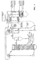
- Fig. 4 illustrate the water/steam circulation system for the CFB/radiant boiler system.
- the system is analogous to that shown in Fig. 2 and 3.
- the system and the process of the present invention can be used with little hardware changes to repower existing boilers, radiant furnaces that burn various carbonaceous fuels including high sulfur, low grade coals, while greatly reducing industrial pollution comprising SO x and NO x .
- SO x and NO x reduction the following is provided.
- NO x reduction in a cyclone fired boiler which generates 0,860 ⁇ 10 -6 g/Nm (2.0 lbs/MM BTU) NO x prior to it being repowered with CFB combustor, based on the amount of heat input by CFB is: 100% CFB heat input 90% NO x reduction 70% CFB heat input 81% NO x reduction.
- PARTS LIST System of repowering industrial and utility boilers (generally) 10 Fluidized bed combustor 20 Fluidized bed combustion chamber 22 Bottom combustion wall of fluidized bed combustion chamber 24 Side combustion wall of fluidized bed combustion chamber 30 & 30' Top combustion wall of fluidized bed combustion chamber 26 Coal inlet to combustion chamber 27 Air inlet to combustion chamber 28 Limestone inlet to combustion chamber 29 Conduit from combustion chamber to hot cyclone 31 Hot cyclone 40 Conduit from hot cyclone to radiant boiler 32 Radiant boiler 60 Bottom wall of radiant boiler 64 Side walls of radiant boiler 62 & 62' Top wall of radiant boiler 66 Coal inlet to radiant boiler 68 Air inlet to radiant boiler 69 Oil or gas inlet to radiant boiler 70 Stack 72 Fluid bed heat exchanger or secondary superheater (FBHE) 100 Heat exchanger fluid line (FBHE) 10 Fluid bed heat exchanger or secondary superheater (FBHE) 100 Heat exchanger fluid line (FBHE) 10 Fluid bed heat exchanger or secondary superheater (FBHE) 100 Heat exchanger fluid line (
Landscapes
- Engineering & Computer Science (AREA)
- Chemical & Material Sciences (AREA)
- Combustion & Propulsion (AREA)
- Physics & Mathematics (AREA)
- Thermal Sciences (AREA)
- Mechanical Engineering (AREA)
- General Engineering & Computer Science (AREA)
- Fluidized-Bed Combustion And Resonant Combustion (AREA)
Claims (10)
- Système pour réalimenter une chaudière industrielle ou utilitaire comportant une unité de combustion à lit fluidisé circulant afin de réduire les émissions de SOx et NOx à l'intérieur de ladite chaudière, ledit système comportant :(a) une unité de combustion à lit fluidisé circulant (20) comportant: une chambre de combustion (22) pour faire brûler un combustible solide carboné à l'intérieur de celle-ci, mélangé avec de la pierre à chaux et de l'air, à une température de l'ordre de 815°C (1500°F) à 928°C (1700°F) afin de produire des gaz d'échappement chauffés ; et un échangeur thermique primaire (80) contenant de l'eau afin de produire de la vapeur saturée à l'intérieur de celui-ci grâce à ladite combustion ;(b) un séparateur de particules dans lequel sont alimentés les gaz d'échappement chauffés contenant des particules et des gaz de fumée afin de séparer les particules des gaz de fumée ;(c) une chaudière (60) comportant : une chambre de combustion pour faire brûler un combustible carboné et de l'air afin de générer de la chaleur et produire des gaz d'échappement chauffés, ladite chambre de combustion de ladite chaudière recevant les gaz de fumée en provenance dudit séparateur de particules à introduire dans la chambre de combustion de ladite chaudière en des quantités telles que les gaz de fumée de la chaudière (60) sont composés d'environ 70 % des gaz de fumée provenant du séparateur de particules et d'environ 30% des gaz d'échappement de combustion générés dans ladite chambre de combustion de ladite chaudière ; et un échangeur thermique secondaire (82) contenant de l'eau à l'intérieur de celui-ci afin de produire de la vapeur saturée grâce à ladite combustion ;(d) des moyens de commande pour fournir entre environ 70 et environ 90 % de la chaleur apportée à ladite chaudière (60) à partir de ladite unité de combustion à lit fluidisé circulant (20) et entre environ 30 et environ 10 % de la chaleur apportée à partir de ladite chaudière (60), de sorte que la quantité totale de chaleur apportée à l'eau alimentée soit égale à la quantité de chaleur apportée à l'unité de combustion (20) plus la quantité de chaleur apportée à la chaudière (60) ;(e) des moyens pour combiner la vapeur saturée provenant de l'échangeur thermique primaire (80) avec la vapeur saturée provenant de l'échangeur thermique secondaire (82) afin d'obtenir un mélange de vapeur saturée ;(f) un surchauffeur primaire (90) situé dans ladite chaudière (60) pour recevoir la vapeur saturée mélangée afin de produire une vapeur surchauffée ;(g) un surchauffeur secondaire (100) situé dans ladite unité de combustion à lit fluidisé (20) pour recevoir et chauffer encore la vapeur surchauffée provenant dudit surchauffeur primaire ; et(1) des moyens pour acheminer ladite vapeur surchauffée vers une turbine à vapeur.
- Système selon la revendication 1, dans lequel le combustible solide carboné, mélangé avec de l'air (28) et de la pierre à chaux (29), est brûlé à une température de l'ordre de 871°C (1600°F).
- Système selon la revendication 1 ou 2, dans lequel ledit séparateur de particules est un séparateur cyclonique chaud (40).
- Système selon l'une quelconque des revendications précédentes, dans lequel ledit combustible solide carboné, brûlé dans ledit lit fluidisé circulant, est un charbon pauvre (27) à forte teneur en sulfure.
- Procédé pour réalimenter une chaudière industrielle ou utilitaire comportant une unité de combustion à lit fluidisé circulant afin de réduire les émissions de SOx et NOx à partir de ladite chaudière, comportant les étapes consistant à :(a) introduire un combustible solide carboné (29), de l'air (28) et de la pierre à chaux (27) à l'intérieur d'une unité de combustion à lit fluidisé circulant (20) qui comporte une chambre de combustion et un échangeur thermique primaire (80) contenant de l'eau ;(b) faire brûler le combustible solide pauvre en présence de pierre à chaux et utiliser ledit lit fluidisé circulant (22) à une température de l'ordre de 871°C (1600°F) afin de produire de la chaleur et des gaz d'échappement contenant des particules solides :(1) le combustible solide carboné subissant une combustion et la pierre à chaux permettant la capture du SOx qui résulte de l'oxydation du sulfure ;(2) la faible libération de chaleur à environ 871°C (1600°F) se traduisant par un NOx faiblement thermique ; et(3) de la vapeur saturée étant produite dans l'échangeur thermique primaire (80) ;(c) séparer les gaz de fumée des particules solides produites à l'étape (b) en utilisant un séparateur de particules ;(d) réintroduire les particules solides séparées dans l'unité de combustion à lit fluidisé (20) pour une meilleure combustion et recirculation ;(e) introduire un mélange de combustible carboné (68) et d'air (69) à l'intérieur d'un foyer de chaudière (60), ledit foyer de chaudière (60) comportant : une chambre de combustion et un échangeur thermique secondaire (82) contenant de l'eau ;(f) faire brûler le mélange pour générer des gaz d'échappement à l'intérieur de la chambre de combustion et produire de la vapeur saturée dans l'échangeur thermique secondaire (82) ;(g) acheminer les gaz de fumée séparés des particules solides à l'étape (c) à l'intérieur de la chambre de combustion du foyer de chaudière (60) et introduire les gaz de fumée dans la zone de combustion de la chambre de combustion du foyer de chaudière (60) afin de former un mélange de gaz comprenant : environ 70 % des gaz de fumée générés à l'intérieur de l'unité de combustion à lit fluidisé circulant (20) ; et environ 30% des gaz d'échappement générés à l'intérieur de la chambre de combustion du foyer de chaudière (60) ;(h) réguler la quantité totale de chaleur produite en maintenant l'apport thermique du lit fluidisé circulant au foyer de chaudière (60) à environ 70 à 90 % et l'apport thermique du foyer de chaudière à environ 30 à 10 % de manière à ce que la quantité totale de chaleur apportée à l'eau alimentée soit égale à la quantité de chaleur apportée à l'unité de combustion (20), plus la quantité de chaleur apportée à la chaudière (60) ;(i) acheminer la vapeur saturée produite dans l'échangeur thermique primaire (80) à l'étape (b) et la mélanger avec la vapeur saturée produite dans l'échangeur thermique secondaire (82) à l'étape (f) ;(j) acheminer la vapeur saturée mélangée dans le surchauffeur primaire (90) situé dans le foyer de chaudière (60) afin de produire une vapeur surchauffée ;(k) acheminer la vapeur surchauffée vers un surchauffeur secondaire (100) situé dans l'unité de combustion à lit fluidisé (20), lequel surchauffeur secondaire peut faire partie intégrante de ladite unité de combustion à lit fluidisé circulant (20) ou en être un composant externe ;(l) réchauffer la vapeur surchauffée dans le surchauffeur secondaire et(m) acheminer (260) la vapeur surchauffée à une entrée d'une turbine à vapeur pour fournir l'énergie nécessaire à la production d'électricité.
- Procédé selon la revendication 5, dans lequel ledit combustible solide carboné à l'intérieur dudit lit fluidisé circulant est un charbon pauvre (27) à forte teneur en sulfure.
- Procédé selon la revendication 5 ou 6, dans lequel ledit séparateur de particules est un séparateur cyclonique chaud (40).
- Procédé selon l'une quelconque des revendications 5 à 7, dans lequel le combustible carboné introduit à l'intérieur du foyer de chaudière est choisi dans le groupe constitué du charbon (68), du pétrole et du gaz (70).
- Procédé selon l'une quelconque des revendications 5 à 8, dans lequel ladite chaudière industrielle ou utilitaire est une chaudière à amorçage cyclonique.
- Procédé selon l'une quelconque des revendications 5 à 8, dans lequel ladite chaudière industrielle et utilitaire est une chaudière radiante (60).
Applications Claiming Priority (2)
| Application Number | Priority Date | Filing Date | Title |
|---|---|---|---|
| US296233 | 1994-08-25 | ||
| US08/296,233 US5535687A (en) | 1994-08-25 | 1994-08-25 | Circulating fluidized bed repowering to reduce Sox and Nox emissions from industrial and utility boilers |
Publications (3)
| Publication Number | Publication Date |
|---|---|
| EP0698763A2 EP0698763A2 (fr) | 1996-02-28 |
| EP0698763A3 EP0698763A3 (fr) | 1996-07-10 |
| EP0698763B1 true EP0698763B1 (fr) | 1999-11-03 |
Family
ID=23141170
Family Applications (1)
| Application Number | Title | Priority Date | Filing Date |
|---|---|---|---|
| EP95113338A Expired - Lifetime EP0698763B1 (fr) | 1994-08-25 | 1995-08-24 | Rénovation de chaudières industrielles ou de centrales avec un lit fluidisé circulant pour réduire les émissions de NOx et de SOx |
Country Status (4)
| Country | Link |
|---|---|
| US (1) | US5535687A (fr) |
| EP (1) | EP0698763B1 (fr) |
| DE (1) | DE69513106T2 (fr) |
| PL (1) | PL180643B1 (fr) |
Families Citing this family (17)
| Publication number | Priority date | Publication date | Assignee | Title |
|---|---|---|---|---|
| DE19528438C2 (de) * | 1995-08-02 | 1998-01-22 | Siemens Ag | Verfahren und System zum Anfahren eines Durchlaufdampferzeugers |
| EP0974471B1 (fr) | 1998-07-23 | 2003-01-22 | ILFORD Imaging Switzerland GmbH | Matériaux d'enregistrement pour l'impression par jet d'encre |
| JP2001050521A (ja) * | 1999-08-06 | 2001-02-23 | Maejima Fumio | 多機能処理装置 |
| US6935251B2 (en) * | 2002-02-15 | 2005-08-30 | American Air Liquide, Inc. | Steam-generating combustion system and method for emission control using oxygen enhancement |
| US20050084434A1 (en) * | 2003-10-20 | 2005-04-21 | Enviroserve Associates, L.L.C. | Scrubbing systems and methods for coal fired combustion units |
| US20080213149A1 (en) * | 2004-08-09 | 2008-09-04 | Richard Gauthier | Process for producing steam and/or power from oil residues |
| US20100126395A1 (en) * | 2004-08-09 | 2010-05-27 | Richard Gauthier | Process for producing steam and/or power from oil residues with high sulfur content |
| ITMI20072291A1 (it) * | 2007-12-06 | 2009-06-07 | Itea Spa | Processo di combustione |
| CN102105656B (zh) * | 2008-02-28 | 2015-11-25 | R·弗格森 | 混合发电装置 |
| DE102008054038B3 (de) * | 2008-10-30 | 2010-04-29 | Karlsruher Institut für Technologie | Verfahren und Vorrichtung zur Reduzierung von Schadstoffemissionen in Verbrennungsanlagen |
| US8496898B2 (en) * | 2010-02-25 | 2013-07-30 | Nol-Tec Systems, Inc. | Fluidized bed carbon dioxide scrubber for pneumatic conveying system |
| US20110265697A1 (en) * | 2010-04-29 | 2011-11-03 | Foster Wheeler North America Corp. | Circulating Fluidized Bed Combustor and a Method of Operating a Circulating Fluidized Bed Combustor |
| US9657937B2 (en) * | 2010-08-23 | 2017-05-23 | Saudi Arabian Oil Company | Steam generation system having multiple combustion chambers and dry flue gas cleaning |
| FI123704B (fi) * | 2011-02-04 | 2013-09-30 | Foster Wheeler Energia Oy | Menetelmä happipolttokiertoleijupetikattilan käyttämiseksi |
| CN103363516B (zh) * | 2013-08-01 | 2015-10-28 | 东方电气集团东方锅炉股份有限公司 | 一种带二次再热的循环流化床锅炉 |
| CN103363517B (zh) * | 2013-08-01 | 2015-10-28 | 东方电气集团东方锅炉股份有限公司 | 一种700℃及以上蒸汽参数的高床温循环流化床锅炉 |
| CA3016349C (fr) * | 2016-03-24 | 2020-09-29 | Her Majesty The Queen In Right Of Canada As Represented By The Minister Of Natural Resources | Systeme et procede de combustion a lit fluidise a gaz oxygene assistee par porteur d'oxygene |
Family Cites Families (24)
| Publication number | Priority date | Publication date | Assignee | Title |
|---|---|---|---|---|
| US4103646A (en) * | 1977-03-07 | 1978-08-01 | Electric Power Research Institute, Inc. | Apparatus and method for combusting carbonaceous fuels employing in tandem a fast bed boiler and a slow boiler |
| US4173950A (en) * | 1978-07-03 | 1979-11-13 | Combustion Engineering, Inc. | Coal fired fluid bed module for a single elevation style fluid bed power plant |
| US4249377A (en) * | 1978-12-21 | 1981-02-10 | Bratt Jan C | Temperature sensing device for a hot gas engine heater head |
| US4309393A (en) * | 1980-10-14 | 1982-01-05 | Domtar Inc. | Fluidized bed sulfur dioxide removal |
| US4936047A (en) * | 1980-11-12 | 1990-06-26 | Battelle Development Corporation | Method of capturing sulfur in coal during combustion and gasification |
| US4380154A (en) * | 1981-06-23 | 1983-04-19 | Thermacore, Inc. | Clean coal power system |
| US4424765A (en) * | 1982-04-26 | 1984-01-10 | Electrodyne Research Corporation | Steam generator having external fluidized bed combustion means |
| US4765258A (en) * | 1984-05-21 | 1988-08-23 | Coal Tech Corp. | Method of optimizing combustion and the capture of pollutants during coal combustion in a cyclone combustor |
| FI79403C (fi) * | 1984-06-01 | 1989-12-11 | Ahlstroem Oy | Foerbraenningsmetod. |
| ES8704252A1 (es) * | 1985-06-28 | 1987-03-16 | Asea Stal Ab | Caldera de lechos fluidizados multiples |
| US4622904A (en) * | 1985-12-13 | 1986-11-18 | The Babcock & Wilcox Company | Combined fluidized bed calciner and pulverized coal boiler and method of operation |
| DE3644030A1 (de) * | 1986-12-22 | 1988-08-04 | Siemens Ag | Aufgeladener, kohlebefeuerter dampferzeuger |
| US4815418A (en) * | 1987-03-23 | 1989-03-28 | Ube Industries, Inc. | Two fluidized bed type boiler |
| SE457015B (sv) * | 1987-03-25 | 1988-11-21 | Abb Stal Ab | Kraftanlaeggning med foerbraenning i fluidiserad baedd |
| US5029557A (en) * | 1987-05-01 | 1991-07-09 | Donlee Technologies, Inc. | Cyclone combustion apparatus |
| HU201230B (en) * | 1987-11-17 | 1990-10-28 | Eszakmagyar Vegyimuevek | Acaricides with synergetic effect and comprising thiophosphoryl glycineamide derivative as active ingredient |
| US5156099A (en) | 1988-08-31 | 1992-10-20 | Ebara Corporation | Composite recycling type fluidized bed boiler |
| US5084258A (en) * | 1988-10-24 | 1992-01-28 | Lin Ping Wha | Lin flue gas SOx /NOx removal process and its by-product utilization |
| US5033413A (en) * | 1989-05-08 | 1991-07-23 | Hri, Inc. | Fluidized bed combustion system and method utilizing capped dual-sided contact units |
| AT394660B (de) * | 1989-07-28 | 1992-05-25 | Staudinger Gernot | Verfahren zur entfernung bzw. verminderung von gasfoermigen schadstoffen und vorrichtung zur durchfuehrung dieses verfahrens |
| US5069685A (en) * | 1990-08-03 | 1991-12-03 | The United States Of America As Represented By The United States Department Of Energy | Two-stage coal gasification and desulfurization apparatus |
| US5178101A (en) | 1992-03-09 | 1993-01-12 | Radian Corporation | Low NOx combustion process and system |
| US5237963A (en) * | 1992-05-04 | 1993-08-24 | Foster Wheeler Energy Corporation | System and method for two-stage combustion in a fluidized bed reactor |
| US5255507A (en) | 1992-05-04 | 1993-10-26 | Ahlstrom Pyropower Corporation | Combined cycle power plant incorporating atmospheric circulating fluidized bed boiler and gasifier |
-
1994
- 1994-08-25 US US08/296,233 patent/US5535687A/en not_active Expired - Fee Related
-
1995
- 1995-08-24 PL PL95310156A patent/PL180643B1/pl not_active IP Right Cessation
- 1995-08-24 DE DE69513106T patent/DE69513106T2/de not_active Expired - Fee Related
- 1995-08-24 EP EP95113338A patent/EP0698763B1/fr not_active Expired - Lifetime
Also Published As
| Publication number | Publication date |
|---|---|
| PL180643B1 (pl) | 2001-03-30 |
| US5535687A (en) | 1996-07-16 |
| PL310156A1 (en) | 1996-03-04 |
| EP0698763A3 (fr) | 1996-07-10 |
| DE69513106T2 (de) | 2000-06-15 |
| EP0698763A2 (fr) | 1996-02-28 |
| DE69513106D1 (de) | 1999-12-09 |
Similar Documents
| Publication | Publication Date | Title |
|---|---|---|
| EP0698763B1 (fr) | Rénovation de chaudières industrielles ou de centrales avec un lit fluidisé circulant pour réduire les émissions de NOx et de SOx | |
| US4602573A (en) | Integrated process for gasifying and combusting a carbonaceous fuel | |
| CA2712870C (fr) | Generation de chaleur a lit fluidise circulant avec combustion dans l'air, adaptee a la capture du co2, avec sous-systeme de reacteur | |
| Beer | Combustion technology developments in power generation in response to environmental challenges | |
| JP3203255B2 (ja) | エネルギー生成のために生物燃料又は屑材料を利用する方法と装置 | |
| CA1120800A (fr) | Methode et installation de production d'electricite par generation de vapeur au charbon | |
| US5236354A (en) | Power plant with efficient emission control for obtaining high turbine inlet temperature | |
| PL203974B1 (pl) | Układ reaktora lub urzadzenia spalajacego z obiegowym złożem fluidalnym wyposażonego w układ selektywnej redukcji katalitycznej | |
| CN104990072A (zh) | 一种高效低NOx排放的流化床锅炉 | |
| CN204756912U (zh) | 一种高效低NOx排放的流化床锅炉 | |
| CN221146517U (zh) | 一种基于中小型燃煤锅炉改造的生物质锅炉 | |
| JP4400467B2 (ja) | 含水廃棄物の燃焼方法及び装置 | |
| JPH05180413A (ja) | 流動層燃焼ボイラ | |
| Teir | Modern boiler types and applications | |
| CN118361727A (zh) | 一种低热值气化细渣的燃烧方法 | |
| CN211734273U (zh) | 一种高效煤气化-燃气锅炉系统和煤炭能源利用系统 | |
| EP0661498A2 (fr) | Procédé pour la récupérations de chaleur | |
| CN114396609A (zh) | 一种用于循环流化床锅炉飞灰利用的系统及方法 | |
| CN101545636A (zh) | 富氧燃烧的煤造气吹风气回收工艺及装置 | |
| Barner et al. | Application of circulating fluid bed technology to the combustion of waste materials | |
| ARRO et al. | Circulating fluidized bed combustion–the technology exact for Estonian oil shale | |
| CN111560269A (zh) | 一种煤气化-燃气锅炉系统与技术方法和煤炭能源利用系统与技术方法 | |
| Topal | Thermal design of a fluidized bed steam boiler using refuse derived fuel (RDF) in organic rankine cycle | |
| JPH1114029A (ja) | 循環流動層燃焼装置及びその運転方法 | |
| RU2321799C1 (ru) | Способ сжигания горючего сланца в котле с циркулирующим псевдоожиженным слоем |
Legal Events
| Date | Code | Title | Description |
|---|---|---|---|
| PUAI | Public reference made under article 153(3) epc to a published international application that has entered the european phase |
Free format text: ORIGINAL CODE: 0009012 |
|
| AK | Designated contracting states |
Kind code of ref document: A2 Designated state(s): DE GB |
|
| PUAL | Search report despatched |
Free format text: ORIGINAL CODE: 0009013 |
|
| AK | Designated contracting states |
Kind code of ref document: A3 Designated state(s): DE GB |
|
| 17P | Request for examination filed |
Effective date: 19961008 |
|
| 17Q | First examination report despatched |
Effective date: 19980116 |
|
| GRAG | Despatch of communication of intention to grant |
Free format text: ORIGINAL CODE: EPIDOS AGRA |
|
| GRAG | Despatch of communication of intention to grant |
Free format text: ORIGINAL CODE: EPIDOS AGRA |
|
| GRAH | Despatch of communication of intention to grant a patent |
Free format text: ORIGINAL CODE: EPIDOS IGRA |
|
| GRAH | Despatch of communication of intention to grant a patent |
Free format text: ORIGINAL CODE: EPIDOS IGRA |
|
| GRAA | (expected) grant |
Free format text: ORIGINAL CODE: 0009210 |
|
| AK | Designated contracting states |
Kind code of ref document: B1 Designated state(s): DE GB |
|
| REF | Corresponds to: |
Ref document number: 69513106 Country of ref document: DE Date of ref document: 19991209 |
|
| PLBE | No opposition filed within time limit |
Free format text: ORIGINAL CODE: 0009261 |
|
| STAA | Information on the status of an ep patent application or granted ep patent |
Free format text: STATUS: NO OPPOSITION FILED WITHIN TIME LIMIT |
|
| 26N | No opposition filed | ||
| REG | Reference to a national code |
Ref country code: GB Ref legal event code: IF02 |
|
| PGFP | Annual fee paid to national office [announced via postgrant information from national office to epo] |
Ref country code: GB Payment date: 20040812 Year of fee payment: 10 |
|
| PGFP | Annual fee paid to national office [announced via postgrant information from national office to epo] |
Ref country code: DE Payment date: 20041029 Year of fee payment: 10 |
|
| PG25 | Lapsed in a contracting state [announced via postgrant information from national office to epo] |
Ref country code: GB Free format text: LAPSE BECAUSE OF NON-PAYMENT OF DUE FEES Effective date: 20050824 |
|
| PG25 | Lapsed in a contracting state [announced via postgrant information from national office to epo] |
Ref country code: DE Free format text: LAPSE BECAUSE OF NON-PAYMENT OF DUE FEES Effective date: 20060301 |
|
| GBPC | Gb: european patent ceased through non-payment of renewal fee |
Effective date: 20050824 |