EP0698986A2 - Procédé pour la compensation adaptative d'écho - Google Patents
Procédé pour la compensation adaptative d'écho Download PDFInfo
- Publication number
- EP0698986A2 EP0698986A2 EP95112666A EP95112666A EP0698986A2 EP 0698986 A2 EP0698986 A2 EP 0698986A2 EP 95112666 A EP95112666 A EP 95112666A EP 95112666 A EP95112666 A EP 95112666A EP 0698986 A2 EP0698986 A2 EP 0698986A2
- Authority
- EP
- European Patent Office
- Prior art keywords
- signal
- step size
- filter
- determined
- short
- Prior art date
- Legal status (The legal status is an assumption and is not a legal conclusion. Google has not performed a legal analysis and makes no representation as to the accuracy of the status listed.)
- Granted
Links
Images


Classifications
-
- H—ELECTRICITY
- H04—ELECTRIC COMMUNICATION TECHNIQUE
- H04M—TELEPHONIC COMMUNICATION
- H04M9/00—Arrangements for interconnection not involving centralised switching
- H04M9/08—Two-way loud-speaking telephone systems with means for conditioning the signal, e.g. for suppressing echoes for one or both directions of traffic
- H04M9/082—Two-way loud-speaking telephone systems with means for conditioning the signal, e.g. for suppressing echoes for one or both directions of traffic using echo cancellers
Definitions
- the invention relates to a method for echo cancellation in a transmission system, in which an undesired coupling between a signal in the transmission direction and a signal in the reception direction occurs.
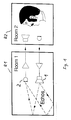
- Such a method is used for technical purposes, for example, in hands-free devices of telecommunication terminals, in which the acoustic coupling from the loudspeaker to the microphone leads to part of the received signal from the loudspeaker via the air gap and possibly a housing to the microphone and thus to the speaker on the other side of the transmission system got back. This part is perceived by the speaker as a disturbing echo.
- the size of the undesired coupling between loudspeaker and microphone is determined by the type of sound transducers, their distance from one another, their directionality and sensitivity and by the environment in which the sound transducers are operated.
- the speaker-microphone coupling factor is determined from the correlation of the microphone signal with the speaker signal.
- a correlation analysis has the disadvantage that incorrect decisions by the correlator cannot be ruled out because of the similarity of the speech signals.
- the computing effort is very large, so that the correlation analysis alone requires about 30% of the total program effort.
- the change in the filter coefficients is controlled depending on the current coupling factor between the loudspeaker and the microphone.
- the coupling factor is determined from the ratio of the electrical signal at the microphone to the electrical signal at the loudspeaker.
- the electrical signal on the loudspeaker is delayed in accordance with the acoustic signal propagation time from the loudspeaker to the microphone, so that the ratio of signals corresponding in time is formed.
- the delay time to be set is determined from the temporal position of the largest filter coefficient with respect to the start of the impulse response of the FIR filter.
- the value of the largest filter coefficient serves as an output variable for normalizing the further filter coefficients, so that an exact representation of the filter coefficients is possible with a value range predetermined by a fixed point computer, for example 16 bits per sample.
- the received signals are applied to the FIR filter of the echo canceller via a high-pass filter with a low cutoff frequency.
- the mean of the difference between the amounts of the direct microphone signal and the compensated microphone signal is constantly checked. If the mean value becomes negative, this indicates an incorrect setting, a so-called overcompensation, of the echo canceller.
- the replication of the echo signal is achieved with a small number of filter coefficients compared to known solutions, so that the FIR filter can also be implemented at low cost.
- an echo canceller can be implemented with little effort, which adapts very quickly and very precisely to different conditions and whose stability is maintained with weak received signals and with local noise signals and with two-way communication.
- Such an echo canceller is used in hands-free systems that enable two or more conversation partners to be naturally entertained.
- the method is general, that is, it can also be used for non-acoustic echo cancellation.
- the step size ⁇ is a measure of the change in the filter coefficients c1 to c N after a recalculation.
- ⁇ In order to achieve a coefficient adaptation to the echo signal at all, ⁇ must be>0; furthermore, ⁇ must be ⁇ 2 in order to avoid instability and overcompensation.
- Overcompensation means coupling the output signal of the FIR filter 5 to the microphone signal instead of a desired negative feedback; the echoes would be amplified. If the step size ⁇ is chosen to be large, the filter coefficients c 1 to c N change very quickly, but there is a risk of overcompensation. With a small step size ⁇ , the risk of incorrect setting is lower, but it takes a long time until the filter coefficients c 1 to c N are adapted to a change in the spatial echo.
- the filter coefficients c 1 to c N are miscalculated a) in the case of two-way communication, that is to say both interlocutors speak simultaneously and b) during the pauses in the conversation, since the amplifier is then adapted to the noise. In these cases, the FIR filter would be set so incorrectly that the return loss from loudspeaker 1 to microphone 2 would be impaired by the echo canceller.
- the filter coefficients c 1 to c N are quickly changed when the impulse response changes, which means, for example, when the position of loudspeaker 1 or microphone 2 changes or when the ambient conditions change significantly; they are changed more slowly if the echo canceller is set well or if measurements are uncertain.
- This is achieved by controlling the step size ⁇ a) as a function of the speaker-microphone coupling dlm remaining after the echo canceller, b) on the quality Q of the excitation, c) on the presence of local speech signals lokspk, d) on the presence of local ones briefly fluctuating noises lnoise and e) detection of overcompensation loss.
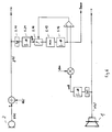
- the short-term level of the microphone signal yeff is first determined from the time signal y (k) on the microphone 2 by forming the amount 5.11 and subsequent integration 5.21.
- the short-term level of the loudspeaker signal xeff is determined from the time signal x (k) on the loudspeaker 1 by forming the amount 5.1 and subsequent integration 5.2.
- the long-term mean value of the reception level reclev is determined from the time signal x (k) on the loudspeaker 1 by forming the amount 5.1 and integrating 5.12.
- the short-term level of the loudspeaker signal xeff In order to obtain the correct assignment of the short-term level of the microphone signal yeff to the short-term level of the loudspeaker signal xeff, the short-term level of the loudspeaker signal xeff must be delayed by at least the acoustic signal propagation time t ak , so that the time delays on the way from the loudspeaker 1 to the microphone 2 and the converter delays are compensated for.
- the short-term level of the loudspeaker signal xeff is delayed by a delay circuit 5.3 and supplies the delayed signal xeffd.
- FIG. 4 shows in the lower part the time course of the coupling signal dlmfakt for a two-way situation.
- the first minimum value detector 5.13 consists of a first storage and comparison circuit 5.6 and a second storage and comparison circuit 5.7 connected downstream thereof, and a counter 5.8.
- the output signal dlmalt of the first storage and comparison circuit 5.6 is constantly renewed to the smaller value of dlmalt and dlmfact and thus searches for the smallest value in the time interval.
- this value dlmalt is taken over by the second storage and comparison circuit 5.7, while the output signal dlmalt of the first storage and comparison circuit 5.6 is set to the current coupling signal dlmfact to search again for the smallest value in the following time interval.
- the second storage and comparison circuit 5.7 compares the instantaneous value of the coupling signal dlmfact with the stored output signal dlmalt of the first storage and comparison circuit 5.6.
- the second storage and comparison circuit 5.7 takes on the smaller value in each case, so that the smallest possible as quickly as possible Worth finding at least.
- the output signal at least of the second storage and comparison circuit 5.7 is filtered with a low-pass filter 5.9 and then provides the best estimate for the loudspeaker-microphone coupling dlm. Possible errors in the estimation of this value are reduced by averaging over time using integrators 5.2 and 5.21 and by filtering using a low-pass filter 5.9, and by evaluating the smallest coupling signal dlmfact.
- the delay circuit 5.3 If the delay ⁇ 1 of the short-term level of the loudspeaker signal xeff is set exactly by the delay circuit 5.3, the low-pass filtering can take place with a significantly higher cut-off frequency and thus a faster adaptation of the estimated value to the current loudspeaker-microphone coupling dlm can be carried out.
- the quality measure Q can advantageously have values between 0 and 1.
- Q f (xeffd) .
- This filter 6 can also be used to implement more complex evaluation functions for Q.
- the sampled values of the loudspeaker signal x (k) can be continuously monitored to determine whether there is a strong broadband signal, noise-like or pulse-shaped, which is used for a quick and precise determination of the filter coefficients c1 to c N is suitable.
- a strong suggestion, for example clapping hands on one side of the conversation partner and silence on the other side would be particularly suitable to quickly provoke a desired setting of the echo canceller.
- the step size ⁇ should only take very small values in order to avoid incorrect setting of the echo canceller.
- ⁇ must not be zero so that a change in the local acoustic situation can still be detected by the echo canceller despite two-way communication.
- German patent application P 43 05 256.8 it has been proposed, for example, to carry out a correlation between the microphone signal z (k) and the delayed time signal x (k- ⁇ ) on the loudspeaker 1 in order to infer an active local speaker at low correlation values.
- a control signal lokspk obtained in this way indicates that one speaks locally and that it speaks zero that one does not speak locally.
- the step size ⁇ is also adapted to the local noise situation.
- the local noise is first determined using a local noise level estimator. 6 shows the basic circuit diagram of the noise level estimator.
- the short-term level of the microphone signal yeff is first determined from the compensated microphone signal y (k) using an absolute value generator 5.11 and an integrator 5.21.
- This level signal is sent via a switch 5.14 to a second minimum value detector 5.15, which in principle is the same as the first minimum value detector 5.13 already described is working.
- the output signal of the second minimum value detector 5.15 gives the estimated value for the noise level lnoise via an integrator 5.16.
- the switch 5.14 the signal components from the short-term level of the microphone signal yeff are hidden from further processing, which can simulate a local noise by means of a received signal from the distant speaker.
- the just-estimated noise level is compared with the short-term level of the loudspeaker signal xeff, which is assessed with the coupling factor dlm. If the noise level is higher, switch 5.14 remains closed.
- the signal-to-noise ratio of the local echo does not deteriorate by the full amount of the noise increase, but by a smaller amount.
- the influence of the background noise on the control of the step size ⁇ can be correspondingly small.
- a low noise level minnoise should hardly have any influence on the step size ⁇ , whereas the step size ⁇ becomes continuously smaller with increasing noise.
- Fig. 7 shows the block diagram of a profit / loss estimator.
- the microphone signal z (k) is given via a first absolute value generator 7.1 and the compensated microphone signal y (k) via a second absolute value generator 7.2 to a subtractor 7.3, the output signal of which provides the desired gain / loss indication with the signal loss via an integrator 7.4.
- the echo canceller contributes to a profit. If the loss signal becomes negative, overcompensation caused by the echo canceller is displayed.
- step size ⁇ The control of the step size ⁇ is explained below from the possibilities of using this information to control the echo canceller.
- the step size ⁇ should be as large as possible to enable rapid adaptation to the new situation.
- the sensitivity of the step size ⁇ is determined by the basic parameters by the choice of the exponents p, m, r. If numbers less than one are chosen for p, m, r, the influence of the associated parameter on the step size ⁇ is greatly reduced.
- the echo canceller described above can advantageously be combined with a compander that is used for the purpose of an adaptive Hands-free device is described in the German patent application P 43 05 256.8 and also in Walker, M .: Hands-Free-A step to natural telecommunications, electrical communications, 2nd quarter 1993, pages 181-187.
- the echo canceller essentially consists of the FIR filter 5, with which the echo signal h (k) is simulated from the received signal x (k) and subtracted from the microphone signal z (k) in a subtracting circuit 6.2.
- the filter coefficients c1 ... c N of the FIR filter 5 are calculated in the adaptation block 6.3.
- the variable step size ⁇ ensures that the setting of the filter coefficients c1 ... c N is carried out quickly and largely without errors.
- the step size ⁇ is controlled as described above.
- the FIR filter 5 is preceded by a variable delay line 6.6, which bridges the time it takes for the sound from the loudspeaker 1 to the microphone 2 to limit the filter length N of the FIR filter 5 to the actual echoes.
- the output signal h1 (k) of the FIR filter 5 is first amplified with a constant factor v1 and then in a 32-bit battery 6.7 with the time-integrated nth power of the largest multiplying occurring filter coefficients.
- the filter coefficients are only saved with a resolution of 16 bits in the inexpensive fixed-point computer used.
- the delay time ⁇ 2 to be set of the delay circuit 6.6 can be determined.
- the compander characteristic curve is set in the block compander of FIG. 8.
- the signals supplied by the microphone 2 as far as they are above a setpoint, are compressed to a uniform signal level, as long as they have the setpoint they remain unchanged and as far as they are below the setpoint, they are further reduced in level.
- the compensated microphone signal y (k) with a bandpass 6.15 is freed from low and high frequency noise, such as impact sound and rumble noise, and thus the frequency range sensitive to the human ear is filtered out.
- the rms value yeff is formed from the compensated microphone signal y (k) with the integrator 5.21.
- the time constants are adapted to the behavior of the human ear.
- the gain value must be reduced proportionally with increasing input level and in the expansion area disproportionately with decreasing input level.
- the transition of the areas is compared in a comparator 6.16 by comparing a threshold signal us with the amount of the compensated Microphone signal
- the threshold signal us is the maximum of the estimated noise level lnoise or the short-term level of the loudspeaker signal xeff evaluated with the coupling factor dlm.
- a switch 6.17 is used to switch between the compression and expansion areas.
- the threshold value us which is determined in comparator 6.16
- the division in circuit block 6.18 must be carried out with the effective value of the loudspeaker signal xeff.
- the amount of the compensated microphone signal reaches
- the division result is averaged by the subsequent integration in integrator 6.19. This results in a smooth transition between the areas of compression and expansion and thus a desired residual dynamic range of around 10dB.
- a standardization variable a is used which fulfills this condition for the largest occurring gain value. 1/1024 is selected for a.
Landscapes
- Engineering & Computer Science (AREA)
- Signal Processing (AREA)
- Cable Transmission Systems, Equalization Of Radio And Reduction Of Echo (AREA)
- Filters That Use Time-Delay Elements (AREA)
- Circuit For Audible Band Transducer (AREA)
Applications Claiming Priority (2)
| Application Number | Priority Date | Filing Date | Title |
|---|---|---|---|
| DE4430189 | 1994-08-25 | ||
| DE4430189A DE4430189A1 (de) | 1994-08-25 | 1994-08-25 | Verfahren zur adaptiven Echokompensation |
Publications (3)
| Publication Number | Publication Date |
|---|---|
| EP0698986A2 true EP0698986A2 (fr) | 1996-02-28 |
| EP0698986A3 EP0698986A3 (fr) | 1998-07-22 |
| EP0698986B1 EP0698986B1 (fr) | 2003-05-28 |
Family
ID=6526557
Family Applications (1)
| Application Number | Title | Priority Date | Filing Date |
|---|---|---|---|
| EP95112666A Expired - Lifetime EP0698986B1 (fr) | 1994-08-25 | 1995-08-11 | Procédé pour la compensation adaptative d'écho |
Country Status (4)
| Country | Link |
|---|---|
| US (1) | US5570423A (fr) |
| EP (1) | EP0698986B1 (fr) |
| AT (1) | ATE241883T1 (fr) |
| DE (2) | DE4430189A1 (fr) |
Cited By (2)
| Publication number | Priority date | Publication date | Assignee | Title |
|---|---|---|---|---|
| WO1997038552A1 (fr) * | 1996-04-03 | 1997-10-16 | British Telecommunications Public Limited Company | Correction acoustique en retour |
| WO1999041848A1 (fr) * | 1998-02-13 | 1999-08-19 | Telefonaktiebolaget Lm Ericsson (Publ) | Procedes et appareils de commande d'adaptation de filtre au bruit |
Families Citing this family (46)
| Publication number | Priority date | Publication date | Assignee | Title |
|---|---|---|---|---|
| US5734715A (en) * | 1995-09-13 | 1998-03-31 | France Telecom | Process and device for adaptive identification and adaptive echo canceller relating thereto |
| SE505152C2 (sv) * | 1995-10-11 | 1997-07-07 | Ericsson Telefon Ab L M | Adaptivt ekosläckningsförfarande |
| DE19611548A1 (de) * | 1996-03-23 | 1997-09-25 | Sel Alcatel Ag | Verfahren und Schaltungsanordnung zur Verbesserung der Übertragungseigenschaften einer echobehafteten Übertragungsstrecke in einem Telekommunikationsnetz |
| KR100200635B1 (ko) * | 1996-10-28 | 1999-06-15 | 윤종용 | 화상회의 시스템에서의 반향제어 장치 및 제어방법 |
| DE19647276A1 (de) * | 1996-11-15 | 1998-05-20 | Alsthom Cge Alcatel | Verfahren und Anordnung zur adaptiven Echokompensation |
| US5943645A (en) * | 1996-12-19 | 1999-08-24 | Northern Telecom Limited | Method and apparatus for computing measures of echo |
| US6160886A (en) * | 1996-12-31 | 2000-12-12 | Ericsson Inc. | Methods and apparatus for improved echo suppression in communications systems |
| DE19702117C1 (de) * | 1997-01-22 | 1997-11-20 | Siemens Ag | Echosperre für ein Spracheingabe Dialogsystem |
| JP3361724B2 (ja) * | 1997-06-11 | 2003-01-07 | 沖電気工業株式会社 | エコーキャンセラ装置 |
| DE19729521B4 (de) * | 1997-07-10 | 2004-04-01 | Deutsche Telekom Ag | Verfahren und Vorrichtung zur Störgeräusch- und Echounterdrückung |
| GB2330746B (en) * | 1997-10-24 | 2002-07-17 | Mitel Corp | Double-talk insensitive NLMS algorithm |
| US6031908A (en) * | 1997-11-14 | 2000-02-29 | Tellabs Operations, Inc. | Echo canceller employing dual-H architecture having variable adaptive gain settings |
| US6570985B1 (en) | 1998-01-09 | 2003-05-27 | Ericsson Inc. | Echo canceler adaptive filter optimization |
| DE19801389A1 (de) | 1998-01-16 | 1999-07-22 | Cit Alcatel | Verfahren zur Echounterdrückung mit adaptiven FIR-Filtern |
| DE19801390A1 (de) | 1998-01-16 | 1999-07-22 | Cit Alcatel | Einrichtung und Verfahren zur Echounterdrückung mit adaptiven FIR-Filtern |
| DE19815942A1 (de) | 1998-04-09 | 1999-10-14 | Cit Alcatel | Vielkanal-Echocanceller mit Compander |
| DE19818609C2 (de) * | 1998-04-20 | 2000-06-15 | Deutsche Telekom Ag | Verfahren und Vorrichtung zur Geräuschfilterung |
| DE19850271A1 (de) | 1998-10-31 | 2000-05-04 | Alcatel Sa | Verfahren zur Bestimmung eines Echokopplungsfaktors und der Echolaufzeit in einem bidirektionalen Telekommunikationssystem |
| FR2791492B1 (fr) * | 1999-03-26 | 2001-06-08 | France Telecom | Procede et dispositif d'identification adaptative, et annuleur d'echo adaptatif mettant en oeuvre un tel procede |
| US6415029B1 (en) | 1999-05-24 | 2002-07-02 | Motorola, Inc. | Echo canceler and double-talk detector for use in a communications unit |
| DE19925046A1 (de) * | 1999-06-01 | 2001-05-03 | Alcatel Sa | Verfahren und Vorrichtung zur Unterdrückung von Rauschen und Echos |
| GB2350969B (en) * | 1999-06-07 | 2003-11-05 | Ericsson Telefon Ab L M | Loudspeaker volume range control |
| DE19928045A1 (de) * | 1999-06-18 | 2000-12-28 | Alcatel Sa | Verfahren und Schaltungsanordnung zur Echokompensation in einem Telekommunikationssystem mit nichtlinearen Übertragungsstrecken |
| US6665402B1 (en) * | 1999-08-31 | 2003-12-16 | Nortel Networks Limited | Method and apparatus for performing echo cancellation |
| CN100499390C (zh) * | 1999-09-10 | 2009-06-10 | 朗迅科技公司 | 回波消除器及利用归一化最小均方算法的回波消除方法 |
| US6898281B1 (en) * | 2000-01-05 | 2005-05-24 | Lucent Technologies Inc. | System and method for filtering echo/NEXT signal interferrence |
| EP1475946A1 (fr) * | 2000-05-12 | 2004-11-10 | Siemens Aktiengesellschaft | Procédé et dispositif d'annulation d'écho utilisant un filtre adaptif |
| DE10030926A1 (de) * | 2000-06-24 | 2002-01-03 | Alcatel Sa | Störsignalabhängige adaptive Echounterdrückung |
| DE10043064B4 (de) * | 2000-09-01 | 2004-07-08 | Dietmar Dr. Ruwisch | Verfahren und Vorrichtung zur Elimination von Lautsprecherinterferenzen aus Mikrofonsignalen |
| DE10119277A1 (de) * | 2001-04-20 | 2002-10-24 | Alcatel Sa | Verfahren zur Maskierung von Geräuschmodulationen und Störgeräuschen bei der Sprachübertragung |
| RU2223599C2 (ru) * | 2001-05-22 | 2004-02-10 | Сибирский государственный университет телекоммуникаций и информатики | Устройство для разделения сигналов передачи в дуплексных системах связи |
| US7171004B2 (en) * | 2002-08-05 | 2007-01-30 | Avaya Technology Corp. | Room acoustics echo meter for voice terminals |
| EP1432221A1 (fr) * | 2002-10-22 | 2004-06-23 | Siemens Aktiengesellschaft | Annulation d'écho a faible retard |
| US7734034B1 (en) | 2005-06-21 | 2010-06-08 | Avaya Inc. | Remote party speaker phone detection |
| US7844453B2 (en) | 2006-05-12 | 2010-11-30 | Qnx Software Systems Co. | Robust noise estimation |
| US8335685B2 (en) * | 2006-12-22 | 2012-12-18 | Qnx Software Systems Limited | Ambient noise compensation system robust to high excitation noise |
| US8107572B1 (en) | 2007-10-12 | 2012-01-31 | Harris Corporation | Communications system using adaptive filter for interference reduction |
| US8204164B1 (en) | 2007-10-12 | 2012-06-19 | Harris Corporation | Communications system using adaptive filter and selected adaptive filter taps |
| US8094763B1 (en) | 2007-10-12 | 2012-01-10 | Harris Corporation | Communications system using adaptive filter with adaptive update gain |
| US8121236B1 (en) | 2007-10-12 | 2012-02-21 | Harris Corporation | Communications system using adaptive filter circuit using parallel adaptive filters |
| US7864835B2 (en) * | 2007-10-12 | 2011-01-04 | Harris Corporation | Communications system using adaptive filter and variable delay before adaptive filter taps |
| US8098781B1 (en) | 2007-10-12 | 2012-01-17 | Harris Corporation | Communications system using adaptive filter with normalization circuit |
| US7860200B2 (en) * | 2007-10-12 | 2010-12-28 | Harris Corporation | Communications system using adaptive filter that is selected based on output power |
| US8081722B1 (en) | 2008-04-04 | 2011-12-20 | Harris Corporation | Communications system and device using simultaneous wideband and in-band narrowband operation and related method |
| CN104575509A (zh) * | 2014-12-29 | 2015-04-29 | 乐视致新电子科技(天津)有限公司 | 语音增强处理方法及装置 |
| EP4325824A1 (fr) * | 2022-08-19 | 2024-02-21 | GN Audio A/S | Haut-parleur et dispositif de serveur pour détermination acoustique de l'environnement et procédés associés |
Citations (1)
| Publication number | Priority date | Publication date | Assignee | Title |
|---|---|---|---|---|
| EP0310055A1 (fr) | 1987-10-02 | 1989-04-05 | Advanced Micro Devices, Inc. | Annuleur d'écho auto-adaptif avec détecteur de double parole |
Family Cites Families (21)
| Publication number | Priority date | Publication date | Assignee | Title |
|---|---|---|---|---|
| US3836734A (en) * | 1971-12-03 | 1974-09-17 | Communications Satellite Corp | Adaptive echo canceller with multi-increment gain coefficient corrections |
| NL7905577A (nl) * | 1979-07-18 | 1981-01-20 | Philips Nv | Inrichting met een niet-recursieffilter. |
| DE3000856A1 (de) * | 1980-01-11 | 1981-07-16 | Licentia Patent-Verwaltungs-Gmbh, 6000 Frankfurt | Adaptive entzerrereinrichtung |
| US4852036A (en) * | 1987-01-07 | 1989-07-25 | Oki Electric Industry Co., Ltd. | Adaptive digital filter and an echo canceler incorporating the same |
| AT391784B (de) * | 1987-11-25 | 1990-11-26 | Siemens Ag Oesterreich | Verfahren zur adaptiven kompensation eines echos in einer kommunikationseinrichtung |
| CA1315356C (fr) * | 1988-07-20 | 1993-03-30 | Seiji Miyoshi | Filtre adaptatif numerique et methode de convergence utilisee par celui-ci |
| US4912758A (en) * | 1988-10-26 | 1990-03-27 | International Business Machines Corporation | Full-duplex digital speakerphone |
| DE3840433A1 (de) * | 1988-12-01 | 1990-06-07 | Philips Patentverwaltung | Echokompensator |
| US4965822A (en) * | 1989-04-10 | 1990-10-23 | Videotelecom Corp. | Full duplex speakerphone |
| US5386472A (en) * | 1990-08-10 | 1995-01-31 | General Motors Corporation | Active noise control system |
| JPH04123621A (ja) * | 1990-09-14 | 1992-04-23 | Nippon Telegr & Teleph Corp <Ntt> | 反響消去装置 |
| DE69131443T2 (de) * | 1990-11-01 | 1999-11-18 | Nec Corp., Tokio/Tokyo | Interferenzunterdrücker mit Steuerung der Gewichtungsfaktorenanpassung mit zum Signalleistungspegel umgekehrt proportionaler Stufenhöhe |
| CA2058495C (fr) * | 1990-12-27 | 1996-02-06 | Akihiko Sugiyama | Filtre adaptable capable de reconnaitre rapidement un systeme inconnu |
| US5278872A (en) * | 1991-05-28 | 1994-01-11 | North American Philips Corporation | System and circuit architecture for echo cancellation and a television receiver comprising same |
| SE469677B (sv) * | 1992-01-10 | 1993-08-16 | Ericsson Telefon Ab L M | Anordning foer att minska risken foer en icke oenskad parameterdrift hos ett adaptivt filter som anvaends foer ekoeliminering |
| US5307405A (en) * | 1992-09-25 | 1994-04-26 | Qualcomm Incorporated | Network echo canceller |
| JP2654894B2 (ja) * | 1992-09-30 | 1997-09-17 | 日本電信電話株式会社 | 反響消去装置およびその方法 |
| JP2508574B2 (ja) * | 1992-11-10 | 1996-06-19 | 日本電気株式会社 | 多チャンネルエコ―除去装置 |
| US5410595A (en) * | 1992-11-12 | 1995-04-25 | Motorola, Inc. | Apparatus and method for noise reduction for a full-duplex speakerphone or the like |
| DE4305256A1 (de) * | 1993-02-20 | 1994-08-25 | Sel Alcatel Ag | Verfahren zum Verbessern der akustischen Rückhördämpfung von elektroakustischen Anlagen |
| CA2117035C (fr) * | 1993-03-05 | 1997-02-18 | Akihiko Sugiyama | Methode et appareil de reconnaissance rapide de systemes meme en presence d'une multiplicite de parties de signal dispersives |
-
1994
- 1994-08-25 DE DE4430189A patent/DE4430189A1/de not_active Withdrawn
-
1995
- 1995-08-11 DE DE59510700T patent/DE59510700D1/de not_active Expired - Fee Related
- 1995-08-11 EP EP95112666A patent/EP0698986B1/fr not_active Expired - Lifetime
- 1995-08-11 AT AT95112666T patent/ATE241883T1/de not_active IP Right Cessation
- 1995-08-25 US US08/519,303 patent/US5570423A/en not_active Expired - Fee Related
Patent Citations (1)
| Publication number | Priority date | Publication date | Assignee | Title |
|---|---|---|---|---|
| EP0310055A1 (fr) | 1987-10-02 | 1989-04-05 | Advanced Micro Devices, Inc. | Annuleur d'écho auto-adaptif avec détecteur de double parole |
Non-Patent Citations (2)
| Title |
|---|
| E. HAENSLER: "The Hands-Free Telephone Problem - An Annotated Bibliography", SIGNAL PROCESSING, vol. 27, no. 3, June 1992 (1992-06-01), pages 259 - 271 |
| T. HUHN, H.-J. JENTSCHEL: "Kombination von Geraeuschreduktion und Echokompensation beim Freisprechen", NACHRICHTENTECHNIK ELKETRONIK, vol. 43, 1993, BERLIN, pages 274 - 280, XP000438838 |
Cited By (4)
| Publication number | Priority date | Publication date | Assignee | Title |
|---|---|---|---|---|
| WO1997038552A1 (fr) * | 1996-04-03 | 1997-10-16 | British Telecommunications Public Limited Company | Correction acoustique en retour |
| AU712787B2 (en) * | 1996-04-03 | 1999-11-18 | British Telecommunications Public Limited Company | Acoustic feedback correction |
| US6389440B1 (en) | 1996-04-03 | 2002-05-14 | British Telecommunications Public Limited Company | Acoustic feedback correction |
| WO1999041848A1 (fr) * | 1998-02-13 | 1999-08-19 | Telefonaktiebolaget Lm Ericsson (Publ) | Procedes et appareils de commande d'adaptation de filtre au bruit |
Also Published As
| Publication number | Publication date |
|---|---|
| ATE241883T1 (de) | 2003-06-15 |
| EP0698986B1 (fr) | 2003-05-28 |
| DE4430189A1 (de) | 1996-02-29 |
| US5570423A (en) | 1996-10-29 |
| DE59510700D1 (de) | 2003-07-03 |
| EP0698986A3 (fr) | 1998-07-22 |
Similar Documents
| Publication | Publication Date | Title |
|---|---|---|
| EP0698986B1 (fr) | Procédé pour la compensation adaptative d'écho | |
| EP0742664B1 (fr) | Méthode pour parler à main levée pour un système de transmission à canaux multiples | |
| DE60108401T2 (de) | System zur erhöhung der sprachqualität | |
| DE69332309T2 (de) | Ausfallgesichertes betriebsverfahren in einem lautfernsprechsystem | |
| DE69429947T2 (de) | Echokompensator | |
| DE69632851T2 (de) | Akustischer Teilband-Echokompensator | |
| DE60024815T2 (de) | System und verfahren zur erkennung eines nahen sprechers durch spektrumanalyse | |
| DE68919807T2 (de) | Vollduplex-digitaler Lautfernsprecher. | |
| DE69331223T2 (de) | Netzwerkechokompensator | |
| DE69631086T2 (de) | Teilbandechokompensationsverfahren unter Verwendung eines Projektionsalgorithmus | |
| DE4305256A1 (de) | Verfahren zum Verbessern der akustischen Rückhördämpfung von elektroakustischen Anlagen | |
| EP0747880B1 (fr) | Système de reconnaissance de la parole | |
| DE69731573T2 (de) | Geräuschverminderungsanordnung | |
| DE10240007A1 (de) | Auffinden von Subband-Echos und Erkennung von Double-Talk in Kommunikationssystemen | |
| DE69604901T2 (de) | Lautsprecher-verstärkungseinstellung für ein freisprech-telekommunikationsendgerät | |
| EP1103956B1 (fr) | Réduction exponentielle de bruit et d'écho pendant les pauses de la parole | |
| DE68916219T2 (de) | Schallabgleichungsanordnung für einen sprachumschaltbaren Lautfernsprecher. | |
| EP3454572A1 (fr) | Procédé de reconnaissance d'un défaut dans un appareil auditif | |
| DE69129719T2 (de) | Sprechvorrichtung mit einer wechselseitigen freisprechfunktion | |
| DE19806015C2 (de) | Verfahren zur Verbesserung der akustischen Rückhördämpfung in Freisprecheinrichtungen | |
| EP1126687A2 (fr) | Procede pour la reduction coordonnée de bruit et/ou d'écho | |
| EP0843455B1 (fr) | Procédé et dispositif d'annulation adaptive d'écho | |
| DE60032047T2 (de) | Verfahren und Vorrichtung zur adaptiven Identifikation und entsprechender adaptiver Echokompensator | |
| DE19709203C2 (de) | Verfahren zum Erzeugen von Meßsignalen für Meßsysteme zum Messen der Übertragungseigenschaften von sich gegenseitig durch Übersprechen beeinflussenden Übertragungsstrecken in elektrischen Nachrichtensystemen, insbesondere von Freisprecheinrichtungen | |
| EP0592787A1 (fr) | Procédé pour améliorer l'affaiblissement du signal local sur des dispostifs électro-acoustiques |
Legal Events
| Date | Code | Title | Description |
|---|---|---|---|
| PUAI | Public reference made under article 153(3) epc to a published international application that has entered the european phase |
Free format text: ORIGINAL CODE: 0009012 |
|
| AK | Designated contracting states |
Kind code of ref document: A2 Designated state(s): AT BE CH DE ES FR GB IT LI NL SE |
|
| PUAL | Search report despatched |
Free format text: ORIGINAL CODE: 0009013 |
|
| AK | Designated contracting states |
Kind code of ref document: A3 Designated state(s): AT BE CH DE ES FR GB IT LI NL SE |
|
| 17P | Request for examination filed |
Effective date: 19980716 |
|
| GRAH | Despatch of communication of intention to grant a patent |
Free format text: ORIGINAL CODE: EPIDOS IGRA |
|
| GRAH | Despatch of communication of intention to grant a patent |
Free format text: ORIGINAL CODE: EPIDOS IGRA |
|
| GRAA | (expected) grant |
Free format text: ORIGINAL CODE: 0009210 |
|
| AK | Designated contracting states |
Designated state(s): AT BE CH DE ES FR GB IT LI NL SE |
|
| PG25 | Lapsed in a contracting state [announced via postgrant information from national office to epo] |
Ref country code: NL Free format text: LAPSE BECAUSE OF FAILURE TO SUBMIT A TRANSLATION OF THE DESCRIPTION OR TO PAY THE FEE WITHIN THE PRESCRIBED TIME-LIMIT Effective date: 20030528 |
|
| REG | Reference to a national code |
Ref country code: GB Ref legal event code: FG4D Free format text: NOT ENGLISH |
|
| REG | Reference to a national code |
Ref country code: CH Ref legal event code: EP |
|
| GBT | Gb: translation of ep patent filed (gb section 77(6)(a)/1977) | ||
| REF | Corresponds to: |
Ref document number: 59510700 Country of ref document: DE Date of ref document: 20030703 Kind code of ref document: P |
|
| PG25 | Lapsed in a contracting state [announced via postgrant information from national office to epo] |
Ref country code: AT Free format text: LAPSE BECAUSE OF NON-PAYMENT OF DUE FEES Effective date: 20030811 |
|
| PG25 | Lapsed in a contracting state [announced via postgrant information from national office to epo] |
Ref country code: SE Free format text: LAPSE BECAUSE OF FAILURE TO SUBMIT A TRANSLATION OF THE DESCRIPTION OR TO PAY THE FEE WITHIN THE PRESCRIBED TIME-LIMIT Effective date: 20030828 |
|
| PG25 | Lapsed in a contracting state [announced via postgrant information from national office to epo] |
Ref country code: LI Free format text: LAPSE BECAUSE OF NON-PAYMENT OF DUE FEES Effective date: 20030831 Ref country code: CH Free format text: LAPSE BECAUSE OF NON-PAYMENT OF DUE FEES Effective date: 20030831 Ref country code: BE Free format text: LAPSE BECAUSE OF NON-PAYMENT OF DUE FEES Effective date: 20030831 |
|
| PG25 | Lapsed in a contracting state [announced via postgrant information from national office to epo] |
Ref country code: ES Free format text: LAPSE BECAUSE OF FAILURE TO SUBMIT A TRANSLATION OF THE DESCRIPTION OR TO PAY THE FEE WITHIN THE PRESCRIBED TIME-LIMIT Effective date: 20030908 |
|
| NLV1 | Nl: lapsed or annulled due to failure to fulfill the requirements of art. 29p and 29m of the patents act | ||
| BERE | Be: lapsed |
Owner name: *ALCATEL SEL A.G. Effective date: 20030831 |
|
| ET | Fr: translation filed | ||
| PLBE | No opposition filed within time limit |
Free format text: ORIGINAL CODE: 0009261 |
|
| STAA | Information on the status of an ep patent application or granted ep patent |
Free format text: STATUS: NO OPPOSITION FILED WITHIN TIME LIMIT |
|
| REG | Reference to a national code |
Ref country code: CH Ref legal event code: PL |
|
| 26N | No opposition filed |
Effective date: 20040302 |
|
| PGFP | Annual fee paid to national office [announced via postgrant information from national office to epo] |
Ref country code: DE Payment date: 20070822 Year of fee payment: 13 |
|
| PGFP | Annual fee paid to national office [announced via postgrant information from national office to epo] |
Ref country code: GB Payment date: 20070823 Year of fee payment: 13 |
|
| PGFP | Annual fee paid to national office [announced via postgrant information from national office to epo] |
Ref country code: IT Payment date: 20070827 Year of fee payment: 13 |
|
| PGFP | Annual fee paid to national office [announced via postgrant information from national office to epo] |
Ref country code: FR Payment date: 20070812 Year of fee payment: 13 |
|
| GBPC | Gb: european patent ceased through non-payment of renewal fee |
Effective date: 20080811 |
|
| REG | Reference to a national code |
Ref country code: FR Ref legal event code: ST Effective date: 20090430 |
|
| PG25 | Lapsed in a contracting state [announced via postgrant information from national office to epo] |
Ref country code: IT Free format text: LAPSE BECAUSE OF NON-PAYMENT OF DUE FEES Effective date: 20080811 Ref country code: DE Free format text: LAPSE BECAUSE OF NON-PAYMENT OF DUE FEES Effective date: 20090303 |
|
| PG25 | Lapsed in a contracting state [announced via postgrant information from national office to epo] |
Ref country code: GB Free format text: LAPSE BECAUSE OF NON-PAYMENT OF DUE FEES Effective date: 20080811 |
|
| PG25 | Lapsed in a contracting state [announced via postgrant information from national office to epo] |
Ref country code: FR Free format text: LAPSE BECAUSE OF NON-PAYMENT OF DUE FEES Effective date: 20090430 |