EP0699012A2 - Schallbildverbesserungsvorrichtung - Google Patents
Schallbildverbesserungsvorrichtung Download PDFInfo
- Publication number
- EP0699012A2 EP0699012A2 EP95108684A EP95108684A EP0699012A2 EP 0699012 A2 EP0699012 A2 EP 0699012A2 EP 95108684 A EP95108684 A EP 95108684A EP 95108684 A EP95108684 A EP 95108684A EP 0699012 A2 EP0699012 A2 EP 0699012A2
- Authority
- EP
- European Patent Office
- Prior art keywords
- signal
- output
- channel
- phase
- phase shifting
- Prior art date
- Legal status (The legal status is an assumption and is not a legal conclusion. Google has not performed a legal analysis and makes no representation as to the accuracy of the status listed.)
- Granted
Links
- 230000010363 phase shift Effects 0.000 claims abstract description 41
- 230000005236 sound signal Effects 0.000 claims description 134
- 230000002238 attenuated effect Effects 0.000 claims description 48
- 230000015654 memory Effects 0.000 claims description 31
- 230000003111 delayed effect Effects 0.000 claims description 16
- 238000012545 processing Methods 0.000 abstract description 30
- 230000006870 function Effects 0.000 description 34
- 238000012546 transfer Methods 0.000 description 22
- 238000010586 diagram Methods 0.000 description 11
- 230000008447 perception Effects 0.000 description 11
- 230000004807 localization Effects 0.000 description 8
- 210000005069 ears Anatomy 0.000 description 6
- 238000005070 sampling Methods 0.000 description 6
- 239000013598 vector Substances 0.000 description 6
- 230000003247 decreasing effect Effects 0.000 description 5
- 230000001934 delay Effects 0.000 description 4
- 230000005540 biological transmission Effects 0.000 description 3
- 230000004044 response Effects 0.000 description 3
- 238000004364 calculation method Methods 0.000 description 2
- 101150089353 cdaS gene Proteins 0.000 description 2
- 230000000694 effects Effects 0.000 description 2
- 230000000737 periodic effect Effects 0.000 description 2
- 230000009467 reduction Effects 0.000 description 2
- 230000008054 signal transmission Effects 0.000 description 2
- 238000004088 simulation Methods 0.000 description 2
- 230000000638 stimulation Effects 0.000 description 2
- 238000012360 testing method Methods 0.000 description 2
- 230000008859 change Effects 0.000 description 1
- 238000012937 correction Methods 0.000 description 1
- 230000000994 depressogenic effect Effects 0.000 description 1
- 238000001514 detection method Methods 0.000 description 1
- 235000019800 disodium phosphate Nutrition 0.000 description 1
- 238000000605 extraction Methods 0.000 description 1
- 230000001771 impaired effect Effects 0.000 description 1
- 238000009434 installation Methods 0.000 description 1
- 238000005259 measurement Methods 0.000 description 1
- 238000000034 method Methods 0.000 description 1
- 238000012986 modification Methods 0.000 description 1
- 230000004048 modification Effects 0.000 description 1
- 230000008569 process Effects 0.000 description 1
- 102220047090 rs6152 Human genes 0.000 description 1
- 230000007480 spreading Effects 0.000 description 1
Images


Classifications
-
- H—ELECTRICITY
- H04—ELECTRIC COMMUNICATION TECHNIQUE
- H04S—STEREOPHONIC SYSTEMS
- H04S1/00—Two-channel systems
- H04S1/002—Non-adaptive circuits, e.g. manually adjustable or static, for enhancing the sound image or the spatial distribution
Definitions
- the present invention relates to a sound image enhancement apparatus suitable for use in acoustic devices and video devices for performing stereophonic sound reproduction.
- a difference signal (L-R) is extracted from left and right channel sound signals L and R. Then, a signal whose level and phase are controlled is added to the left channel sound signal L, while a signal of opposite phase relative to the signal having the controlled level and phase is added to the right channel sound signal R.
- a sound image enhancement circuit 1' has a structure shown in Fig. 23.
- the left channel sound signal L and the right channel sound signal R are input to left and right channel input terminals 2L and 2R, respectively.
- the left channel sound signal L is sent to an adder 6L, while a signal of opposite phase relative to the left channel sound signal L is output to an adder 3.
- the right channel sound signal R is sent to the adder 3 and an adder 6R.
- a difference signal (L-R) is generated based on the input left and right channel sound signal L and R
- the level of the difference signal (L-R) is attenuated by a predetermined amount by an attenuator 4 with an attenuation coefficient A. Then, a signal [(L-R) ⁇ A] is sent to a phase shifter 5.
- phase shifter 5 the phase of the input signal [(L-R) ⁇ A] is shifted by ⁇ , and a signal [(L-R) ⁇ A] ⁇ (where ⁇ represents the phase) is sent to the adder 6L.
- a signal -[(L-R) ⁇ A] ⁇ of opposite phase relative to the input signal [(L-R) ⁇ A] ⁇ is sent to the adder 6R.
- an output of the phase shifter 5 and the left channel sound signal L are added, and a signal [L+((L-R) ⁇ A) ⁇ ] is output as a reproduced sound output from an output terminal 7L.
- a virtual speaker 10L' is located on a line connecting speakers 10L and 10R along the direction of the synthetic vector as shown in Fig. 24.
- a virtual speaker 10R' is located on a line connecting the speakers 10L and 10R along the direction of the synthetic vector. Such a placement of the virtual speakers 10L' and 10R' is achieved by adjusting the attenuator 4 and the phase shifter 5.
- the sound image enhancement circuit 1' performs analog processing using an analog circuit. However, it is also possible to obtain similar results by performing digital processing using a DSP (Digital Signal Processor).
- DSP Digital Signal Processor
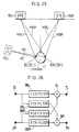
- a virtual sound source is generated on the basis of a transfer function.
- the transfer function is given according to the order of an FIR (Finite Impulse Response) filter, processed by the DSP.
- FIR Finite Impulse Response
- E L L ⁇ H AL + R ⁇ H BL
- E R L ⁇ H AR + R ⁇ H BR
- E L ' S L ⁇ H L
- E R ' S L ⁇ H R
- the transfer functions are actually given by obtaining the order of (the number of steps in) the FIR filter using, for example, a window function with respect to the results of measurement at the positions of the speakers 10L and 10R and the position of the virtual speaker 10L'.
- reverberation signals are generated based on input sound signals using a delay circuit, added to the input sound signals, and then reproduced by two front speakers.
- two rear speakers may be provided at the back in addition to the two front speakers so that the reverberation signals are reproduced by the rear speakers.
- An object of the present invention is to provide an inexpensive sound enhancement apparatus capable of spreading a sound image to the back of a listener and simulating the perception of a live performance.
- a first sound image enhancement apparatus of the present invention is based on a sound image enhancement apparatus for reproducing two-channel stereo signals with speakers, and includes the following means for each channel.
- each channel of the first sound image enhancement apparatus includes: additional signal generating means for subtracting from a stereo input signal of one of the two channels a stereo input signal of the other channel which has been attenuated by a first attenuation coefficient, and outputting the resulting signal as an additional signal; first phase shifting means for attenuating the additional signal by a second attenuation coefficient, and introducing a predetermined phase shift to the attenuated signal; second phase shifting means for attenuating the additional signal by a third attenuation coefficient, correcting a frequency characteristic thereof, and introducing a predetermined phase shift to the resulting signal; first summing means for inverting a phase of an output of the first phase shifting means, and adding the inverted output to the stereo input signal of the other channel; and second summing means for inverting a phase of an output of the second phase shifting means, adding the inverted output to an output of the first summing means, and sending the resulting sum to the speaker of the other channel.
- the additional signal generated by the additional signal generating means is attenuated by the second attenuation coefficient, and then phase-shifted by a predetermined amount by the first phase shifting means.
- the additional signal is attenuated by the third attenuation coefficient, receives a frequency characteristic correction, and is then phase-shifted by a predetermined amount by the second phase shifting means.
- the phase of the output of the first phase shifting means is inverted, and the inverted signal is sent to the first summing means.
- the first summing means adds up the inverted output and the stereo input signal of the other channel.
- the phase of the output of the second phase shifting means is inverted, and the inverted output is sent to the second summing means.
- the second summing means adds up the inverted output and the output of the first summing means.
- the above-discussed processing is also performed for the other channel.
- the above-mentioned structure accurately orients virtual speakers at the back of the listener by adjusting the amounts of phase shift of the first and second phase shifting means as well as the respective attenuation coefficients.
- a second sound image enhancement apparatus of the present invention includes second summing means for inverting the phase of the output of the second phase shifting means and adding the inverted output to the output of the first summing means, in place of the second summing means of the first sound image enhancement apparatus, and further includes: delaying and attenuating means for delaying the output of the second phase shifting means of the other channel, and attenuating the delayed output by a fourth attenuation coefficient; and third summing means for adding up the output of the delaying and attenuating means and the output of the second summing means, and sending the resulting sum to the speaker of the other channel.
- the output of the second phase shifting means of the other channel is delayed and attenuated by the fourth attenuation coefficient by the delaying and attenuating means, and sent to the third summing means.
- the third summing means adds up the output of the delaying and attenuating means and the output of the second summing means, and sends the resulting sum to the speaker of the other channel.
- the delaying and attenuating means forms a type of a comb filter, frequency components in the stereo input signal are attenuated or emphasized according to the amounts of delay. It is therefore possible to widen the low and mid frequency band sounds and to correct the signal level of high frequency band.
- a third sound image enhancement apparatus of the present invention is based on the first or second sound image enhancement apparatus, wherein the first phase shifting means includes: a plurality of band-pass means, provided for each of predetermined frequency bands, for transmitting only input signals within the predetermined frequency bands; delaying means for introducing a predetermined phase delay to an output of each of the band-pass means; and fourth summing means for adding up outputs of the delaying means, and wherein the second phase shifting means includes an IIR-type digital low-pass filter.
- the first phase shifting means signals passed the respective band-pass means are phase-delayed by predetermined amounts by the delaying means and sent to the fourth summing means.
- the fourth summing means the outputs of the all of the delaying means are added up.
- the second phase shifting means is formed by an IIR-type digital low-pass filter. It is therefore possible to ensure widening of a sound image with a simplified structure. Additionally, since the number of processing steps is decreased, it is possible to orient virtual speakers at the back of the listener with an inexpensive DSP but without using a high-speed DSP.
- a fourth sound image enhancement apparatus of the present invention is a sound image enhancement apparatus for reproducing two-channel stereo signals with speakers, and includes the following means for each channel.
- the fourth sound image enhancement apparatus includes: additional signal generating means for subtracting from a stereo input signal of one of the two channels a stereo input signal of the other channel which has been attenuated by a first attenuation coefficient, and outputting the resulting signal as an additional signal; first phase shifting means for attenuating the additional signal by a second attenuation coefficient, and introducing a predetermined phase shift to the attenuated signal; second phase shifting means for attenuating the additional signal by a third attenuation coefficient, correcting a frequency characteristic thereof, and introducing a predetermined phase shift to the resulting signal; first summing means for inverting a phase of an output of the first phase shifting means, and adding the inverted output to the stereo input signal of the other channel; second summing means for inverting a phase of an output of the second phase shifting means, and adding the inverted output to an output of the first summing means; fourth summing means for adding up the additional signal and an additional signal of the other channel; fifth summing means for
- the phases of the additional signals of both of the channels are shifted by the same second phase shifting means. After the output of the second phase shifting means is added to the additional signals of both of the channels, the resulting signal is delayed and attenuated by the delaying and attenuating means. It is thus possible to surely prevent the phase shift from causing a decrease of the output in transmission from the third summing means to the speaker.
- a fifth sound image enhancement apparatus of the present invention is a sound image enhancement apparatus for reproducing two-channel stereo signals with speakers, and includes the following means for each channel.
- the fifth sound image enhancement apparatus includes: additional signal generating means for subtracting from a stereo input signal of one of the two channels a stereo input signal of the other channel which has been attenuated by a first attenuation coefficient, and outputting the resulting signal as an additional signal; first phase shifting means for attenuating the additional signal by a second attenuation coefficient, and introducing a predetermined phase shift to the attenuated signal; first summing means for attenuating the additional signal by a third attenuation coefficient, and adding up the attenuated signal and an output of the first phase shifting means; second phase shifting means for correcting a frequency characteristic of an output of the first summing means, and introducing a predetermined phase shift to the resulting signal; second summing means for inverting a phase of an output of the second phase shifting means, and adding the inverted output to the stereo input signal of the other channel; delaying and attenuating means for delaying an output of the second phase shifting means of the other channel, and attenuating the delayed
- the additional signal is attenuated by the second attenuation coefficient, and then phase-shifted by a predetermined amount by the first phase shifting means. Thereafter, the additional signal is attenuated by the third attenuation coefficient, and sent to the first summing means. Then, the attenuated output and the output of the first phase shifting means are added up by the first summing means.
- the phase of the resulting output is shifted by a predetermined amount by the second phase shifting means.
- the phase of the output of the second phase shifting means is inverted, and the inverted output is sent to the second summing means.
- the inverted output is added to the stereo input signal of the other channel.
- the output of the delaying and attenuating means and the output of the second summing means are added up by the third summing means, and sent to the speaker of the other channel.
- the amount of phase shift becomes larger compared with the case where the first phase shifting means and the second phase shifting means are performed in parallel. As a result, the variable range of the locations of the virtual speakers is widened.
- a sixth sound image enhancement apparatus of the present invention is based on the first sound image enhancement apparatus, and includes: additional signal generating means for subtracting from a second reverberation sound signal of one of the two channels a second reverberation sound signal of the other channel which has been attenuated by a first attenuation coefficient, and outputting the resulting signal as an additional signal; first summing means for inverting a phase of an output of the first phase shifting means, and adding the inverted output to the second reverberation sound signal of the other channel; and second summing means for inverting a phase of an output of the second phase shifting means, and adding the inverted output to an output of the first summing means, in place of the additional signal generating means, the first summing means and the second summing of the first sound image enhancement apparatus, respectively, and further includes: reverberation sound signal generating means for generating, for each channel, a first reverberation sound signal to be reproduced by the speaker
- the first reverberation sound signal generated based on the stereo input signal is reproduced as a reverberation sound by the speaker.
- the second reverberation sound signal generated based on the stereo input signal is subjected to sound image enhancement processing, and then reproduced as a reverberation sound by the virtual speaker.
- a seventh sound image enhancement apparatus of the present invention is based on the first or second sound image enhancement apparatus, and includes: additional signal generating means for subtracting from a second reverberation sound signal of one of the two channels a second reverberation sound signal of the other channel which has been attenuated by a first attenuation coefficient, and outputting the resulting signal as an additional signal; first summing means for inverting a phase of an output of the first phase shifting means, and adding the inverted output to the second reverberation sound signal of the other channel; and third summing means for adding up an output of the delaying and attenuating means and an output of the second summing means, in place of the additional signal generating means, the first summing means and the third summing means of the first or second image sound enhancement apparatus, and further includes: reverberation sound signal generating means for generating, for each channel, the first reverberation sound signal to be reproduced by the speaker in one channel and the second
- the first reverberation sound signal generated based on the stereo input signal is reproduced as a reverberation sound by the speaker.
- the second reverberation sound signal generated based on the stereo input signal is subjected to sound image enhancement processing, and then reproduced as a reverberation sound by the virtual speaker.
- reverberation sounds of two different types are reproduced by the speaker and the virtual speaker, respectively, it is possible to reproduce reverberation sounds from the front, back and sides of the listener depending on the combined state of the two types of reverberation sounds, thereby simulating a sound field at a live performance.
- an eighth sound image enhancement apparatus of the present invention is based on the fifth sound image enhancement apparatus, and includes: additional signal generating means for subtracting from a second reverberation sound signal of one of the two channels a second reverberation sound signal of the other channel which has been attenuated by a first attenuation coefficient, and outputting the resulting signal as an additional signal; second summing means for inverting a phase of an output of the second phase shifting means, and adding the inverted output to the second reverberation sound signal of the other channel; and third summing means for adding up an output of the delaying and attenuating means and an output of the second summing means, in place of the additional signal generating means, the second summing means and the third summing of the fifth sound image enhancement apparatus, and further includes: reverberation sound signal generating means for generating, for each channel, the first reverberation sound signal to be reproduced by the speaker in one channel and the second reverberation sound
- the first reverberation sound signal generated based on the stereo input signal is reproduced as a reverberation sound by the speaker.
- the second reverberation sound signal generated based on the stereo input signal is subjected to sound image enhancement processing, and then reproduced as a reverberation sound by the virtual speaker.
- reverberation sounds of two different types are reproduced by the speaker and the virtual speaker, respectively, it is possible to reproduce reverberation sounds from the front, back and sides of the listener depending on the combined state of the two types of reverberation sounds, thereby simulating a sound field at a live performance.
- Fig. 1 is a block diagram showing an example of the structure of essential sections of a sound image enhancement apparatus of the present invention.
- Fig. 2 is a block diagram showing the structure of the sound image enhancement apparatus of the present invention.
- Fig. 3 is an explanatory view showing a relationship among a listener, speakers, and virtual speakers.
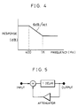
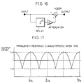
- Fig. 4 shows a frequency characteristic of an equalizer.
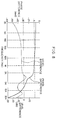
- Fig. 5 is an explanatory view showing the structure of a second phase shifter.
- Fig. 6 is an explanatory view for explaining a theory of sound image localization.
- Fig. 7 is an explanatory view showing the level of a signal fell on the right ear relative to a signal at the entrance of the external auditory meatus of the left ear, and the phase difference between the signals, plotted at a frequency when real sound sources are moved.
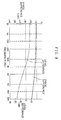
- Fig. 8 is an explanatory view showing the frequency characteristic of a level difference and a phase difference in the right channel with respect to the left channel, introduced by a first phase shifter.
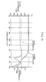
- Fig. 9 is an explanatory view showing the frequency characteristic of an output signal of a second phase shifter in the right channel with respect to an input signal of the left channel.
- Fig. 10 is an explanatory view showing synthetic results of Figs. 8 and 9.
- Fig. 11 is an explanatory view showing the frequency characteristic of a phase difference and level difference when the angle of a virtual speaker is 60°.
- Fig. 12 is an explanatory view showing the frequency characteristic of a phase difference and level difference when the angle of the virtual speaker is 120°.
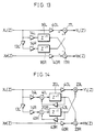
- Fig. 13 is a diagram of an equivalent circuit of a simplified circuit of the first phase shifter.
- Fig. 14 is a diagram of an equivalent circuit of a simplified circuit of a second phase shifter.
- Fig. 15 is a block diagram showing an example of the structure of essential sections of another sound image enhancement apparatus of the present invention.
- Fig. 16 is a diagram of an equivalent circuit, which shows that delaying and attenuating means of the present invention forms a type of a comb filter.
- Fig. 18 is a block diagram showing the structure of essential sections of another sound image enhancement apparatus of the present invention.
- Fig. 19 is a block diagram showing the structure of essential sections of still another sound image enhancement apparatus of the present invention.
- Fig. 20 is an explanatory view showing an area within which the listener is movable in forward, backward, left and right directions, and angles of speakers.
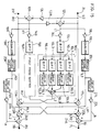
- Fig. 21 is a block diagram showing an example in which a reverberation sound signal generating circuit is provided in the front stage of the sound image enhancement apparatus.
- Fig. 22 is an explanatory view showing a specific example of the reverberation sound signal generating circuit.
- Fig. 23 is a block diagram showing the structure of essential sections of a conventional sound image enhancement circuit.
- Fig. 24 is an explanatory view showing a relationship between speakers and virtual speakers of the conventional example.
- Fig. 25 is an explanatory view showing a conventional example of sound image enhancement based on a transfer function.
- Fig. 26 is an explanatory view showing an example in which a conventional sound image enhancement circuit is formed by an FIR filter.
- two channels of stereo signals L and R are input to a sound image enhancement apparatus 1 of the present invention from a sound source 8 through a left channel input terminal 2L and a right channel input terminal 2R, respectively.
- the sound source 8 includes an input switching device 8d.
- the input switching device 8d is selectively switched to a CD (Compact Disk) player 8a, a tuner 8b and a cassette tape recorder 8c, and outputs a signal to be reproduced from one of these sound sources.
- CD Compact Disk
- the sound image enhancement device 1 a variety of processing for widening a sound image to the back of a listener using only two front speakers is performed on the basis of the input signals to be reproduced. The result is transmitted to the speakers 10L and 10R through output terminals 7L and 7R, volume controllers VR L , VR R and amplifiers 9L and 9R, respectively. The sounds are reproduced through the speakers 10L and 10R.
- a display device 51 and a key input section 52 are connected to the sound image enhancement apparatus 1 through a microcontroller 50. These devices are provided so as to switch a surround function between on and off and control the sound image.
- the surround function is switched between on and off using a predetermined key.
- the angle of each virtual speaker and the dimensions of a sound image are varied using predetermined keys.
- the display device 51 displays "Surround ON"
- the attenuation coefficient of each of attenuators 14L and 14R (to be described later) shown in Fig. 1 is changed from, for example, 0 to 0.9
- the attenuation coefficient of each of attenuators 18L and 18R (to be described later) shown in Fig. 1 is changed from, for example, 0 to 0.6 under the control of the microcontroller 50.
- signals processed by a first phase shifter 16L (16R) and a second phase shifter 20L (20R) are added to the other channel, and reproduced through the speaker 10R (10L). Consequently, a virtual speaker is realized.
- the reference numerals in the brackets correspond to members in the other channel series.
- the selected setting is displayed by the display device 51, and an amount of phase shift of the second phase shifter 20L (20R) and the attenuation coefficient of the attenuator 18L (18R) are changed to pre-recorded values under the control of the microcontroller 50. It is thus possible to control the position of the virtual speaker from the front to back of the listener, realizing spaces of sound image desired by the listener.
- the right channel sound signal R0 is transmitted to an attenuator 13R with an attenuation coefficient a (the first attenuation coefficient) where it is attenuated and its phase is inverted, and then sent to an adder 12L.
- a the first attenuation coefficient
- the adder 12L the left channel sound signal L0 is input, and the left channel sound signal L0 and the right channel sound signal R0 are added up and output as an additional signal L1.
- the additional signal L1 is sent through an attenuator 14L with an attenuation coefficient b (the second attenuation coefficient) to a band-pass filter (BPF) 15L so that only components within a frequency band requiring a phase control are sent to the first phase shifter 16L.
- BPF band-pass filter
- the first phase shifter 16L is provided for controlling the phase so that the opposite phase components are reduced at the listener position.
- the first phase shifter 16L includes four band-pass filters 16L1, 16L2, 16L3, 16L4, and delay circuits 16L5, 16L6, 16L7, 16L8 for introducing a delay in the transmission of the respective outputs of band-pass filters.
- the frequency band requiring a phase control is divided into four frequency bands by the band-pass filters 16L1, 16L2, 16L3, 16L4.
- the delay circuits 16L5, 16L6, 16L7, 16L6 introduce a predetermined delay in the transmission of signal in each frequency band so that the phase of each of the signals is shifted by ⁇ 11, ⁇ 12, ⁇ 13, and ⁇ 14, respectively.
- An amount of phase shift ⁇ 1 in the first phase shifter 16L varies depending on the frequency.
- the outputs of the delay circuits 16L5, 16L6, 16L7, 16L8 are added up in an adder 16L9, and output as a signal L2.
- the resulting signal L2 is sent to an adder 17R.
- a signal RL1 expressed by the following equation is output by an adder 17R.
- the additional signal L1 is sent through the attenuator 18L with an attenuation coefficient c (the third attenuation coefficient) to an equalizer 19L where a low frequency band is emphasized, and then transmitted to the second phase shifter 20L.
- the second phase shifter 20L includes a simple IIR-type digital low-pass filter.
- a signal (-L3) is produced by inverting the phase of L3, and transmitted to an adder 23R.
- ⁇ 2 in equation (12) represents an amount of phase shift provided by the second phase shifter 20L.
- the signal (-L3) and the signal RL1 are added up in the adder 23R, and a signal RL2 is output.
- the signal RL2 is expressed by the following equation, and output to the output terminal 7R.
- a signal R3 is given as follows.
- the left channel sound signal L0 is sent to an attenuator 13L with the attenuation coefficient a where it is attenuated and its phase is inverted, and transmitted to the adder 12R.
- a right channel sound signal R0 is input to the adder 12R.
- the right channel sound signal R0 and the left channel sound signal L0 are added up, and output as an additional signal R1.
- the additional signal R1 is sent through the attenuator 18R with the attenuation coefficient c to an equalizer 19R where low frequency bands are emphasized, and then transmitted to the second phase shifter 20R.
- the second phase shifter 20R includes a simple low-pass filter.
- the additional signal R1 given by equation (14) above is sent through an attenuator 14R with an attenuation coefficient b to a band-pass filter (BPF) 15R so that only components within a frequency band requiring a phase control are sent to the first phase shifter 16R.
- the first phase shifter 16R is provided for controlling the phase so that the opposite phase components are reduced at the listener position.
- the first phase shifter 16R includes four band-pass filters 16R1, 16R2, 16R3, 16R4 (not shown), and delay circuits 16R5, 16R6, 16R7, 16R8 (not shown) for introducing a delay in the transmission of the respective outputs.
- the frequency band requiring a phase control is divided into four frequency bands by the band-pass filters 16R1, 16R2, 16R3, 16R4.
- the delay circuits 16R5, 16R6, 16R7, 16R8 introduce a predetermined delay in the transmission of signal in each frequency band so that the phase of each of the signals is shifted by ⁇ 11, ⁇ 12, ⁇ 13, and ⁇ 14, respectively.
- An amount of phase shift ⁇ 1 provided by the first phase shifter 16R varies depending on the frequency.
- the outputs of the delay circuits 16R5, 16R6, 16R7, 16R8 are added up in an adder 16R9 (not shown), and output as a signal R2.
- the signal R2 is sent to an adder 17L.
- a signal LR1 is output by the adder 17L.
- a signal (-R3) is produced by inverting the phase of R3 represented by equation (15) above, and transmitted to an adder 23L.
- the signal (-R3) and the signal LR1 are added up in the adder 23L, and a signal LR2 is output.
- the signal LR2 is expressed by the following equation, and sent to the output terminal 7L.
- the number of processing steps in the DSP in the above-mentioned structure is calculated as follows.
- each attenuator it is necessary to provide three attenuators, five BPFs, one equalizer, four delay circuits, seven adders, and one second phase shifter for each channel. It is also necessary to arrange the order of each attenuator to be 2, the order of each BPF to be 6, the order of the equalizer to be 6, the order of readout in each delay circuit to be 2, the order of writing in each delay circuit to be 2, the order of each adder to be 1, and the order of the second phase shifter to be 4.
- the attenuation coefficients and the delays become as follows.
- the speakers 10L and 10R are installed on lines directed laterally outwardly and forwardly at 30° on either side of the listener as illustrated in Fig. 3.
- the pass band of the band-pass filter 15L is between 200 Hz to 10 kHz.
- the band-pass filter 16L1 is a low-pass filter with a cut-off frequency of 500 Hz.
- the pass band of the band-pass filter 16L2 is between 500 Hz and 2 kHz.
- the pass band of the band-pass filter 16L3 is between 2 kHz and 5 kHz.
- the band-pass filter 16L4 is a high-pass filter with a cut-off frequency of 5 kHz.
- a delay given by the delay circuit 16L5 is between 8 f S and 10 f S .
- the delay of the delay circuit 16L6 is between 5 f S and 8 f S .
- the delay of the delay circuit 16L7 is between 4 f S and 7 f S .
- the delay of the delay circuit 16L8 is between 3 f S and 6 f S .
- the equalizer 19L has the frequency characteristic shown in Fig. 4.
- the second phase shifter 20L is a low-pass filter having the structure shown in Fig. 5 (a feedback by the attenuator is not higher than 0.7, and the position of the virtual speaker 10L' is adjusted by the feedback and the attenuation coefficient c of the attenuator 18L). With these settings, the phase and attenuation described by the sound image localization theory were obtained.
- a sound image produced by in-phase signals in stereo reproduction is generally said to be a sharp sound image.
- a sound image produced by signals with a phase difference or time difference is usually said to be vague.
- a sound source located in a position a degrees off-axis from the front-center position is judged a rear sound source located in a direction shifted at (180- ⁇ ) degrees from the front position, i.e., a so-called wrong judgement is made.
- the wrong judgement was made because the level difference and phase difference extremely approximate to each other.
- the phase difference between the left and right signals is about 0.95 ⁇ or 1.05 ⁇ at frequencies not higher than 2 kHz and the level difference to a value corresponding to an angle of the virtual speaker.
- a level x and a phase ⁇ of the right channel with reference to the left channel are calculated by the following equations.
- x [(A 2 + B 2 )/(C 2 + D 2 )] 1/2
- ⁇ tan -1 (A/B) + tan -1 (D/C)
- x and ⁇ to satisfy 3 dB ⁇ x ⁇ 4 dB , and 0.95 ⁇ ⁇ ⁇ ⁇ 1.05 ⁇ .
- the phase difference is obtained by adding ⁇ (180°) to ⁇ .
- phase difference and level difference between the signal LR1 based on the first phase shifter 16R and the signal RL1 based on the first phase shifter 16L vary as follows. As illustrated in Fig. 8, the phase difference varies within a range between (- ⁇ ) and -( ⁇ +0.1 ⁇ ) over a range of mid-frequency band (500 Hz to 2 kHz), while the phase difference varies within a range between -( ⁇ -0.1 ⁇ ) and (- ⁇ ) at frequencies not higher than 500 Hz.
- phase difference and the level difference between the signal R3 based on the second phase shifter 20R and the left channel sound signal L0 vary as follows. As illustrated in Fig. 9, the phase difference varies within a range between (- ⁇ ) and -( ⁇ +0.1 ⁇ ) over a range of low frequency band.
- the level difference is amplified by about (+8) dB over the range of low frequency band, and attenuated over a range of high frequency band as shown by the curve in Fig. 9.
- Fig. 10 shows the combined characteristics of Figs. 8 and 9. It is possible to achieve a phase difference of (- ⁇ 0.1 ⁇ ) and a level difference of (4 to 3) dB within a range of frequencies from 50 Hz to 1.8 kHz. These phase difference and the level difference are equal to the values taught by the sound image localization theory.
- the virtual speaker angle up to 90°. Since the symmetrical phase characteristics are shown between angles 0° to 90° and 180° to 90°, if the virtual speaker angle becomes equal to or larger than 90°, the phase control is infeasible. The characteristics when the virtual speaker angle was 60° and 120° were obtained by the transfer function characteristics. The results are shown in Figs. 11 and 12. In comparison with the virtual speaker angle of 60°, when the virtual speaker angle is 120°, the increase of the level within a range of low frequency band becomes larger than the increase of the level within a range of high frequency band.
- the virtual speaker placed on a line directed laterally forwardly at 60° relative to the listener position by way of the first phase shifter 16R and 16L (see Fig. 8). Similar characteristics to those of a speaker angle 120° are obtained by using the equalizers 19R and 19L and the second phase shifters 20R and 20L (see Fig. 10), and a rear virtual speaker (with a virtual speaker angle between 90° and 180°) is simulated.
- phase difference characteristic depending on the first phase shifters 16R and 16L approximate to that of the front located virtual speaker (60°) (i.e., the phase difference characteristic of Fig. 8 and that of Fig. 11 approximate to each other) and that the phase difference characteristic obtained by the addition of the second phase shifters 20R and 20L approximates to that of the rear located virtual speaker (120°) (i.e., the phase difference characteristic of Fig. 10 and that of Fig. 12 approximate to each other).
- Figs. 13 and 14 the following description will explain how to obtain the respective attenuation coefficients for sound image enhancement for only one channel signal (for example, for only a left channel signal).
- the members having the same function as in the above-mentioned embodiment will be designated by the same code and their description will be omitted.
- the characteristic depending on the first phase shifter is obtained by an equivalent circuit of a simplified circuit shown in Fig. 13.
- the left channel stereo signal L (right channel stereo signal R) is attenuated by an attenuator 40L (40R).
- a delay coefficient n of each of the delay circuits 16L and 16R varies depending on the frequency. In the following given example, a specific frequency is set at 400 Hz.
- the level of widening of a sound image is set at 60° by the first phase shifter.
- the level of H RL (e j ⁇ T ) and the phase to be 4.5 dB and 0.05 ⁇ (the minus sign being ignored), respectively, the following equations are established.
- the delay coefficient n is determined depending on the specific frequency.
- the delay coefficient n is finally determined by dividing the frequencies lower than 5 kHz into four ranges because of the amount of calculation and by performing an adjustment with reference to the values given by the equations so that the phase angle is obtained at the center frequency of each range.
- the characteristic depending on the second phase shifter is obtained by an equivalent circuit of a simplified circuit shown in Fig. 14.
- a transfer function h L (Z) of the left channel and a transfer function h R (Z) of the right channel are expressed by equations (40) and (41) below.
- the output of the attenuator 14L (14R) and the output of the attenuator 43L (43R) are added up in the adder 41L (41R), and sent to the second phase shifter 20L (20R).
- the attenuation coefficient of each of the attenuators is obtained for the case where the first phase shifter and the second phase shifter are provided, and the sound image enhancement characteristic shown in Fig. 10 is obtained as mentioned above.
- the values of the attenuation coefficients are not limited to the above-mentioned values. If K and c are positive values not larger than 1 and set to prevent an overflow in the calculation of the circuit, the sound image enhancement characteristic shown in Fig. 10 is obtained.
- An example given here with reference to Fig. 15 differs from the structure shown in Fig. 1 due to the following points 1) and 2).
- An adder 24L (third summing means) is provided between the adder 23L and the output terminal 7L, the output signal L3 of the second phase shifter 20L is delayed and attenuated by a delay circuit 21L (delaying and attenuating means, delayed phase ⁇ 3) and an attenuator 22L (delaying and attenuating means, attenuation coefficient d) and input to the adder 24L, and the output signal LR2 of the adder 23L is also input to the adder 24L.
- a delay circuit 21L delaying and attenuating means, delayed phase ⁇ 3
- an attenuator 22L delaying and attenuating means, attenuation coefficient d
- An adder 24R (third summing means) is provided between the adder 23R and the output terminal 7R, the output signal R3 of the second phase shifter 20R is delayed and attenuated by a delay circuit 21R (delaying and attenuating means, delayed phase ⁇ 3) and an attenuator 22R (delaying and attenuating means, attenuation coefficient d) and input to the adder 24R, and the output signal RL2 of the adder 23R is also input to the adder 24R.
- a delay circuit 21R delaying and attenuating means, delayed phase ⁇ 3
- an attenuator 22R delaying and attenuating means, attenuation coefficient d
- R4 S R + S C - b[S L - aS R + (1-a)S C ] ⁇ 1 - c ⁇ (S L - aS R + (1-a)S C ) ⁇ 2 + c ⁇ d(S R - aS L + (1-a)S C )( ⁇ 2 + ⁇ 3 )
- L4 S L + S C - b[S R - aS L + (1-a)S C ] ⁇ 1 - c ⁇ (S R - aS L + (1-a)S C ) ⁇ 2 + c ⁇ d(S L - aS R + (1-a)S C )( ⁇ 2 + ⁇ 3 )
- the signals L4 and R4 are expressed by equations (49) and (50) below, respectively.
- the delay circuit 21L and the attenuator 22L form a kind of a comb filter, and its equivalent circuit is shown in Fig. 16.
- the delay is N and the attenuation coefficient is d, the frequency characteristic of the comb filter is obtained based on the impulse response.
- H(Z) 1 + d ⁇ Z -N
- equation (54) is developed to equation (55) below.
- H(e j ⁇ t ) d(2cos(N ⁇ t/2) ⁇ e -jN ⁇ t/2 )+(1-d)
- the amplitude of H(e jN ⁇ t ) changes at 2d ⁇ cos(N ⁇ t/2) .
- the structure of Fig. 18 differs from that of Fig. 15 because of the following two points. Namely, the structure of Fig. 18 is based on the structure of Fig. 15, and further includes an adder 27 for adding up the output of the adder 12L and the output of the adder 12R.
- an adder 28L (28R) for adding up the output of the second phase shifter 20L (20R) and the output of the adder 27 is additionally provided, and the output of the adder 28L (28R) is sent to the delay circuit 21L (21R).
- a signal d(L1+R1+L3) ⁇ 3 is sent to the adder 24L.
- the structure of Fig. 19 includes an adder 25L (25R) for adding up the output of an attenuator 18L (18R) and the output L2 (R2) of the first phase shifter 16L (16R), but does not include the adder 17R (17L) shown in the structure of Fig. 15. Namely, the output L2 (R2) of the first phase shifter 16L (16R) is sent to the adder 25L (25R).
- the reference numerals in the brackets correspond to members of the other channel.
- An output -L3' is produced by inverting the phase of the output L3', and then sent to the adder 23R.
- the signals L4 (see equation (48)) and R4 (see equation (47)) in the parallel processing shown in Fig. 15 and the signals L4' (see equation (67)) and R4' (see equation (68)) in the sequential processing shown in Fig. 19 are compared.
- the sequential processing (the structure of Fig. 19) has a larger number of phase terms than the parallel processing (the structure of Fig. 15). Moreover, with the sequential processing, it is possible to increase the phase shift by ( ⁇ 1 + ⁇ 2 + ⁇ 3 ) . It is thus possible to easily adjust the position of the virtual speaker in a wider range.
- the relationship between the position of the listener and the positions of the speakers is based on the placement of the listener positioned with the speakers 10L and 10R on lines directed laterally outwardly and forwardly at 30° on either side of the listener.
- the virtual speakers 10L' and 10R' are most effectively positioned at the back of the listener.
- the listener is movable from the center line between the left and right speakers 10L and 10R to the left and right, respectively, by substantially 20 cm to 30 cm which is equivalent to the heads of two people.
- the listener is movable by a distance around a maximum of 5 m and a minimum of 30 cm from the front faces of the speakers 10L and 10R although the value varies depending on the condition of the listening room and the volume of the speakers.
- the speaker angle is varied in a range of from a minimum of around 5° to a maximum of around 60° by adjusting the second phase shifter 20L and the attenuator 18L (the second phase shifter 20R and the attenuator 18R) (see Fig. 20).
- Fig. 20 The above-mentioned structure is illustrated in Fig. 20.
- the angles of the left and right speakers are registered at 30°, respectively.
- the limitation in positioning a virtual speaker at the back of the listener is equivalent to the limitation in the case where the position of the listener is moved substantially by 20 percent of the distance from the front faces of the speakers 10L and 10R to the listener in a forward or backward direction.
- the speaker angle when the speaker angle is not fixed, a user registers the position of the listener, and the amount of shift of the second phase shifter 20L and the attenuation coefficient of the attenuator 13R (the amount of shift of the second phase shifter 20R and the attenuation coefficient of attenuator 13L) are set depending on the registered position, thereby simulating virtual speakers at the back of the listener.
- the virtual speakers are simulated at the back of the listener by decreasing the amount of shift of the second phase shifter when the speaker angle is increased and by increasing the amount of shift when the speaker angle is decreased.
- the speaker angle is decreased to near 5°, the increased crosstalk occurs when sounds from the left and right speakers 10L and 10R reach the ears of the listener.
- the sound image at the back of the listener is likely to be lost, and widening of sounds, particularly, mid and high frequency band sounds, is impaired.
- the speaker angles with the range of from 10° to 60° are equally divided, and matched with pre-registered amounts of shift and attenuation.
- the listener position is easily registered by inputting numerical values corresponding to desired amounts or selecting the desired amounts using setting means.
- the sound image enhancement apparatus 1 shown in Fig. 21 may have any one of the structures of the above-mentioned sound enhancement apparatuses.
- a reverberation sound signal generating circuit 29 (reverberation sound signal generating means) is provided at a front stage of the sound enhancement apparatus 1.
- the reverberation sound signal generating circuit 29 has the structure shown in Fig. 22.
- the left channel series includes a delay memory group 61, a plurality of attenuators 62 to 67, and a plurality of adders 60, 68, 69 and 70
- the right channel series includes a delay memory group 72, a plurality of attenuators 73 to 78, and a plurality of adders 71, 79, 80 and 81.
- a stereo signal L (R) from the sound source 8 is input through an input terminal 29a (29b) to the adder 60 (71).
- the stereo signal L (stereo signal R) and an output of attenuator 67 (78) are added up, and sent to the delay memory group 61 (72).
- the delay memory group 61 (72) includes a first memory 61a (72a) to a fifth memory 61e (72e).
- the input sum signal is first stored in the first memory 61a (72a).
- a desired delay time is obtained by setting an address of the first memory 61a (72a) after the elapse of the desired time and reading out the stored signal. Addresses allocated for the second memory 61b (72b) to the fifth memory 61e (72e) are different from each other. Therefore, desired delay times are obtained by reading out the sum signal at a desired time point, which was stored by setting the respective addresses after the elapse of the desired times.
- An output of the fifth memory 61e (72e) is attenuated by a predetermined attenuation coefficient of the attenuator 67 (78), sent to the adder 60 (71), and added to the stereo signal L (stereo signal R).
- the output of the fifth memory 61e (72e) is fed back to the first memory 61a (72a), reverberation sound signals are continuously produced.
- the signal read from the first memory 61a (72a) is input to the attenuator 62 (73), attenuated by a predetermined attenuation coefficient, and sent to the adder 68 (79).
- the signal read from the second memory 61b (72b) is input to the attenuator 63 (74), attenuated by a predetermined attenuation coefficient, and sent to the adder 68 (79).
- the adder 68 (79) the outputs of the attenuators 62 and 63 (73 and 74) are added up, and sent to the adder 69 (80).
- the adder 69 (80) the output of the adder 68 (79) and the signal which was read from the third memory 61c (72c) and attenuated by a predetermined attenuation coefficient are added up, and sent as a first reverberation sound signal from the output terminal 29c (29f) to the adder 30L (30R) as six summing means.
- the stereo signal L (stereo signal R) and the first reverberation sound signal are added up, the resulting signal is added to a sound image enhanced signal from the output terminal 7L (7R) in the left channel (right channel) of the sound image enhancement apparatus 1, and sent to the volume controller VR L (VR R ).
- the first reverberation sound signal is used as a reflected sound from the front.
- signals read out from the fourth memory 61d (72d) and the fifth memory 61e (72e) are attenuated by predetermined attenuation coefficients in the attenuator 65 (76) and the attenuator 66 (77), respectively, added up in the adder 70 (81), and sent as a second reverberation sound signal from the output terminal 29d (29e) to the input terminal 2L (2R) of the left channel (right channel) of the sound image enhancement apparatus 1 where sound image enhancement processing is performed.
- the second reverberation sound signal is used as a reflected sound from the back.
- the output of the adder 30L (30R) is sent to the adder 31L (31R) as seventh summing means, and added to an output signal to which sound image enhancement processing has been applied based on the second reverberation sound signal by the sound image enhancement apparatus 1.
- the output of the adder 31L (31R) is sent to the speaker 10L (10R) through the volume controller VR L (VR R ) and the amplifier 9L (9R).
- the left channel series is explained.
- the right channel series will also be explained in the same way, and numerals indicated in brackets correspond to the right channel series.
- the sum signal of the first reverberation sound signal and the stereo signal L becomes a reverberation sound reproduced by the front speaker 10L.
- the second reverberation sound signal to which sound image enhancement processing was applied becomes a reverberation sound reproduced by a virtual rear left speaker.
- the sum signal of the first reverberation sound signal and the stereo signal R becomes a reverberation sound reproduced by the front speaker 10R.
- the second reverberation sound signal to which sound image enhancement processing was applied becomes a reverberation sound reproduced by a virtual rear right speaker.
- the number of attenuators (the number of delays) for obtaining the first reverberation sound signal is not particularly limited to the above mentioned number, three.
- the number of attenuators (the number of delays) for obtaining the second reverberation sound signal is not particularly limited to the above mentioned number, two. Namely, if the amounts of delay of the first and second reverberation sound signals satisfy the above-mentioned relationship, the number of attenuators is freely changed.
- the left channel or the right channel is explained as an independent delay memory group.
- it is possible to obtain the first and second reverberation sound signals by, for example, mixing the stereo signals L and R in both the channels. It is also possible to use a delay output of the left channel as a reverberation sound signal of the right channel. Namely, structures for obtaining the first and second reverberation sound signals are suitably selected depending on a desired sound field.
Landscapes
- Physics & Mathematics (AREA)
- Engineering & Computer Science (AREA)
- Acoustics & Sound (AREA)
- Signal Processing (AREA)
- Stereophonic System (AREA)
- Reverberation, Karaoke And Other Acoustics (AREA)
Applications Claiming Priority (6)
| Application Number | Priority Date | Filing Date | Title |
|---|---|---|---|
| JP19942594 | 1994-08-24 | ||
| JP199425/94 | 1994-08-24 | ||
| JP19942594 | 1994-08-24 | ||
| JP7677395 | 1995-03-31 | ||
| JP07677395A JP3276528B2 (ja) | 1994-08-24 | 1995-03-31 | 音像拡大装置 |
| JP76773/95 | 1995-03-31 |
Publications (3)
| Publication Number | Publication Date |
|---|---|
| EP0699012A2 true EP0699012A2 (de) | 1996-02-28 |
| EP0699012A3 EP0699012A3 (de) | 1997-12-03 |
| EP0699012B1 EP0699012B1 (de) | 2002-03-27 |
Family
ID=26417904
Family Applications (1)
| Application Number | Title | Priority Date | Filing Date |
|---|---|---|---|
| EP95108684A Expired - Lifetime EP0699012B1 (de) | 1994-08-24 | 1995-06-06 | Schallbildverbesserungsvorrichtung |
Country Status (4)
| Country | Link |
|---|---|
| US (1) | US5657391A (de) |
| EP (1) | EP0699012B1 (de) |
| JP (1) | JP3276528B2 (de) |
| DE (1) | DE69526008T2 (de) |
Cited By (15)
| Publication number | Priority date | Publication date | Assignee | Title |
|---|---|---|---|---|
| WO1997041711A1 (en) * | 1996-04-30 | 1997-11-06 | Srs Labs, Inc. | Audio enhancement system for use in a surround sound environment |
| US5850453A (en) * | 1995-07-28 | 1998-12-15 | Srs Labs, Inc. | Acoustic correction apparatus |
| US5892830A (en) * | 1995-04-27 | 1999-04-06 | Srs Labs, Inc. | Stereo enhancement system |
| EP0917400A3 (de) * | 1997-11-18 | 2000-09-20 | Onkyo Corporation | Vorrichtung und Verfahren zur Schallbildlocalisierung |
| WO2000059265A1 (en) * | 1999-03-31 | 2000-10-05 | Qsound Labs, Inc. | Matrix surround decoder/virtualizer |
| US6281749B1 (en) | 1997-06-17 | 2001-08-28 | Srs Labs, Inc. | Sound enhancement system |
| GB2377869A (en) * | 2001-07-17 | 2003-01-22 | Sunplus Technology Co Ltd | Stereo sound circuit device for providing three-dimensional surrounding effect |
| EP0977464A3 (de) * | 1998-07-31 | 2005-04-13 | Onkyo Corporation | Tonsignalverarbeitungsschaltung |
| US7003119B1 (en) | 1997-05-19 | 2006-02-21 | Qsound Labs, Inc. | Matrix surround decoder/virtualizer |
| US7031474B1 (en) | 1999-10-04 | 2006-04-18 | Srs Labs, Inc. | Acoustic correction apparatus |
| US7200236B1 (en) | 1996-11-07 | 2007-04-03 | Srslabs, Inc. | Multi-channel audio enhancement system for use in recording playback and methods for providing same |
| US7277767B2 (en) | 1999-12-10 | 2007-10-02 | Srs Labs, Inc. | System and method for enhanced streaming audio |
| US8050434B1 (en) | 2006-12-21 | 2011-11-01 | Srs Labs, Inc. | Multi-channel audio enhancement system |
| US9088858B2 (en) | 2011-01-04 | 2015-07-21 | Dts Llc | Immersive audio rendering system |
| US9164724B2 (en) | 2011-08-26 | 2015-10-20 | Dts Llc | Audio adjustment system |
Families Citing this family (38)
| Publication number | Priority date | Publication date | Assignee | Title |
|---|---|---|---|---|
| US5692050A (en) * | 1995-06-15 | 1997-11-25 | Binaura Corporation | Method and apparatus for spatially enhancing stereo and monophonic signals |
| US5761313A (en) * | 1995-06-30 | 1998-06-02 | Philips Electronics North America Corp. | Circuit for improving the stereo image separation of a stereo signal |
| JP2956545B2 (ja) * | 1995-08-28 | 1999-10-04 | ヤマハ株式会社 | 音場制御装置 |
| US5872851A (en) * | 1995-09-18 | 1999-02-16 | Harman Motive Incorporated | Dynamic stereophonic enchancement signal processing system |
| JP3107006B2 (ja) * | 1996-09-30 | 2000-11-06 | ヤマハ株式会社 | 音場拡大器 |
| JP3498888B2 (ja) * | 1996-10-11 | 2004-02-23 | 日本ビクター株式会社 | サラウンド信号処理装置と方法及び映像音声再生方法、記録媒体への記録方法及び記録装置、記録媒体、処理プログラムの伝送方法及び受信方法、並びに記録データの伝送方法及び受信方法 |
| JP3900208B2 (ja) * | 1997-02-06 | 2007-04-04 | ソニー株式会社 | 音響再生方式および音声信号処理装置 |
| JP3740670B2 (ja) * | 1997-05-20 | 2006-02-01 | 株式会社河合楽器製作所 | ステレオ音像拡大装置 |
| US5983087A (en) * | 1997-06-26 | 1999-11-09 | Delco Electronics Corporation | Distributed digital signal processing for vehicle audio systems |
| JP3657120B2 (ja) | 1998-07-30 | 2005-06-08 | 株式会社アーニス・サウンド・テクノロジーズ | 左,右両耳用のオーディオ信号を音像定位させるための処理方法 |
| JP3880236B2 (ja) * | 1999-02-05 | 2007-02-14 | 株式会社アーニス・サウンド・テクノロジーズ | ステレオ再生用のオーディオ信号の再生音をスピーカ外に音像定位させる方法 |
| US6522758B1 (en) | 1999-08-18 | 2003-02-18 | Sound Advance Systems, Inc. | Compensation system for planar loudspeakers |
| DE19956690A1 (de) * | 1999-11-25 | 2001-07-19 | Harman Audio Electronic Sys | Beschallungseinrichtung |
| WO2001060118A1 (en) * | 2000-02-11 | 2001-08-16 | Tc Electronic A/S | Audio center channel phantomizer |
| US7457425B2 (en) * | 2001-02-09 | 2008-11-25 | Thx Ltd. | Vehicle sound system |
| US7254239B2 (en) * | 2001-02-09 | 2007-08-07 | Thx Ltd. | Sound system and method of sound reproduction |
| US7433483B2 (en) | 2001-02-09 | 2008-10-07 | Thx Ltd. | Narrow profile speaker configurations and systems |
| US6999590B2 (en) * | 2001-07-19 | 2006-02-14 | Sunplus Technology Co., Ltd. | Stereo sound circuit device for providing three-dimensional surrounding effect |
| US7684574B2 (en) * | 2003-05-27 | 2010-03-23 | Harman International Industries, Incorporated | Reflective loudspeaker array |
| US7826622B2 (en) * | 2003-05-27 | 2010-11-02 | Harman International Industries, Incorporated | Constant-beamwidth loudspeaker array |
| US7680289B2 (en) * | 2003-11-04 | 2010-03-16 | Texas Instruments Incorporated | Binaural sound localization using a formant-type cascade of resonators and anti-resonators |
| TWI246866B (en) * | 2004-01-09 | 2006-01-01 | Mediatek Inc | Method and device for digital audio signal processing |
| US7856110B2 (en) | 2004-02-26 | 2010-12-21 | Panasonic Corporation | Audio processor |
| WO2006057521A1 (en) * | 2004-11-26 | 2006-06-01 | Samsung Electronics Co., Ltd. | Apparatus and method of processing multi-channel audio input signals to produce at least two channel output signals therefrom, and computer readable medium containing executable code to perform the method |
| KR100608024B1 (ko) * | 2004-11-26 | 2006-08-02 | 삼성전자주식회사 | 다중 채널 오디오 입력 신호를 2채널 출력으로 재생하기위한 장치 및 방법과 이를 수행하기 위한 프로그램이기록된 기록매체 |
| WO2006092995A1 (ja) * | 2005-03-01 | 2006-09-08 | Pioneer Corporation | 音響再生装置 |
| JP4581831B2 (ja) * | 2005-05-16 | 2010-11-17 | ソニー株式会社 | 音響装置、音響調整方法および音響調整プログラム |
| KR100739776B1 (ko) * | 2005-09-22 | 2007-07-13 | 삼성전자주식회사 | 입체 음향 생성 방법 및 장치 |
| WO2007046288A1 (ja) * | 2005-10-18 | 2007-04-26 | Pioneer Corporation | 定位制御装置、定位制御方法、定位制御プログラムおよびコンピュータに読み取り可能な記録媒体 |
| KR100636252B1 (ko) * | 2005-10-25 | 2006-10-19 | 삼성전자주식회사 | 공간 스테레오 사운드 생성 방법 및 장치 |
| US7920708B2 (en) * | 2006-11-16 | 2011-04-05 | Texas Instruments Incorporated | Low computation mono to stereo conversion using intra-aural differences |
| US8233629B2 (en) * | 2008-09-04 | 2012-07-31 | Dts, Inc. | Interaural time delay restoration system and method |
| US8666081B2 (en) * | 2009-08-07 | 2014-03-04 | Lg Electronics, Inc. | Apparatus for processing a media signal and method thereof |
| CN102667918B (zh) | 2009-10-21 | 2015-08-12 | 弗兰霍菲尔运输应用研究公司 | 用于使音频信号混响的混响器和方法 |
| JP2011176566A (ja) * | 2010-02-24 | 2011-09-08 | Jvc Kenwood Holdings Inc | 残響付加装置、プログラム、及び残響付加方法 |
| JP5672741B2 (ja) * | 2010-03-31 | 2015-02-18 | ソニー株式会社 | 信号処理装置および方法、並びにプログラム |
| JP5787128B2 (ja) * | 2010-12-16 | 2015-09-30 | ソニー株式会社 | 音響システム、音響信号処理装置および方法、並びに、プログラム |
| JP6261998B2 (ja) * | 2014-01-31 | 2018-01-17 | 新日本無線株式会社 | 音響信号処理装置 |
Family Cites Families (7)
| Publication number | Priority date | Publication date | Assignee | Title |
|---|---|---|---|---|
| US4218585A (en) * | 1979-04-05 | 1980-08-19 | Carver R W | Dimensional sound producing apparatus and method |
| JP2854306B2 (ja) * | 1988-11-05 | 1999-02-03 | 四一 安藤 | 音響再生装置 |
| US5067157A (en) * | 1989-02-03 | 1991-11-19 | Pioneer Electronic Corporation | Noise reduction apparatus in an FM stereo tuner |
| JPH03171900A (ja) * | 1989-11-29 | 1991-07-25 | Pioneer Electron Corp | 狭空間用音場補正装置 |
| US5121433A (en) * | 1990-06-15 | 1992-06-09 | Auris Corp. | Apparatus and method for controlling the magnitude spectrum of acoustically combined signals |
| US5235646A (en) * | 1990-06-15 | 1993-08-10 | Wilde Martin D | Method and apparatus for creating de-correlated audio output signals and audio recordings made thereby |
| US5305386A (en) * | 1990-10-15 | 1994-04-19 | Fujitsu Ten Limited | Apparatus for expanding and controlling sound fields |
-
1995
- 1995-03-31 JP JP07677395A patent/JP3276528B2/ja not_active Expired - Fee Related
- 1995-06-06 EP EP95108684A patent/EP0699012B1/de not_active Expired - Lifetime
- 1995-06-06 US US08/471,455 patent/US5657391A/en not_active Expired - Fee Related
- 1995-06-06 DE DE69526008T patent/DE69526008T2/de not_active Expired - Fee Related
Non-Patent Citations (1)
| Title |
|---|
| None |
Cited By (37)
| Publication number | Priority date | Publication date | Assignee | Title |
|---|---|---|---|---|
| US5892830A (en) * | 1995-04-27 | 1999-04-06 | Srs Labs, Inc. | Stereo enhancement system |
| US7636443B2 (en) | 1995-04-27 | 2009-12-22 | Srs Labs, Inc. | Audio enhancement system |
| US6597791B1 (en) | 1995-04-27 | 2003-07-22 | Srs Labs, Inc. | Audio enhancement system |
| US6718039B1 (en) | 1995-07-28 | 2004-04-06 | Srs Labs, Inc. | Acoustic correction apparatus |
| US5850453A (en) * | 1995-07-28 | 1998-12-15 | Srs Labs, Inc. | Acoustic correction apparatus |
| US7555130B2 (en) | 1995-07-28 | 2009-06-30 | Srs Labs, Inc. | Acoustic correction apparatus |
| US7043031B2 (en) | 1995-07-28 | 2006-05-09 | Srs Labs, Inc. | Acoustic correction apparatus |
| US5970152A (en) * | 1996-04-30 | 1999-10-19 | Srs Labs, Inc. | Audio enhancement system for use in a surround sound environment |
| WO1997041711A1 (en) * | 1996-04-30 | 1997-11-06 | Srs Labs, Inc. | Audio enhancement system for use in a surround sound environment |
| US8472631B2 (en) | 1996-11-07 | 2013-06-25 | Dts Llc | Multi-channel audio enhancement system for use in recording playback and methods for providing same |
| US7200236B1 (en) | 1996-11-07 | 2007-04-03 | Srslabs, Inc. | Multi-channel audio enhancement system for use in recording playback and methods for providing same |
| US7492907B2 (en) | 1996-11-07 | 2009-02-17 | Srs Labs, Inc. | Multi-channel audio enhancement system for use in recording and playback and methods for providing same |
| US7003119B1 (en) | 1997-05-19 | 2006-02-21 | Qsound Labs, Inc. | Matrix surround decoder/virtualizer |
| US6281749B1 (en) | 1997-06-17 | 2001-08-28 | Srs Labs, Inc. | Sound enhancement system |
| EP0917400A3 (de) * | 1997-11-18 | 2000-09-20 | Onkyo Corporation | Vorrichtung und Verfahren zur Schallbildlocalisierung |
| US7801312B2 (en) | 1998-07-31 | 2010-09-21 | Onkyo Corporation | Audio signal processing circuit |
| EP1571883A1 (de) * | 1998-07-31 | 2005-09-07 | Onkyo Corporation | Tonsignalverarbeitungsschaltung |
| EP0977464A3 (de) * | 1998-07-31 | 2005-04-13 | Onkyo Corporation | Tonsignalverarbeitungsschaltung |
| WO2000059265A1 (en) * | 1999-03-31 | 2000-10-05 | Qsound Labs, Inc. | Matrix surround decoder/virtualizer |
| US7031474B1 (en) | 1999-10-04 | 2006-04-18 | Srs Labs, Inc. | Acoustic correction apparatus |
| US7907736B2 (en) | 1999-10-04 | 2011-03-15 | Srs Labs, Inc. | Acoustic correction apparatus |
| US8751028B2 (en) | 1999-12-10 | 2014-06-10 | Dts Llc | System and method for enhanced streaming audio |
| US7277767B2 (en) | 1999-12-10 | 2007-10-02 | Srs Labs, Inc. | System and method for enhanced streaming audio |
| US7467021B2 (en) | 1999-12-10 | 2008-12-16 | Srs Labs, Inc. | System and method for enhanced streaming audio |
| US7987281B2 (en) | 1999-12-10 | 2011-07-26 | Srs Labs, Inc. | System and method for enhanced streaming audio |
| US8046093B2 (en) | 1999-12-10 | 2011-10-25 | Srs Labs, Inc. | System and method for enhanced streaming audio |
| GB2377869A (en) * | 2001-07-17 | 2003-01-22 | Sunplus Technology Co Ltd | Stereo sound circuit device for providing three-dimensional surrounding effect |
| GB2377869B (en) * | 2001-07-17 | 2005-07-06 | Sunplus Technology Co Ltd | Stereo sound circuit device for providing three dimensional surrounding effect |
| US8050434B1 (en) | 2006-12-21 | 2011-11-01 | Srs Labs, Inc. | Multi-channel audio enhancement system |
| US8509464B1 (en) | 2006-12-21 | 2013-08-13 | Dts Llc | Multi-channel audio enhancement system |
| US9232312B2 (en) | 2006-12-21 | 2016-01-05 | Dts Llc | Multi-channel audio enhancement system |
| US9088858B2 (en) | 2011-01-04 | 2015-07-21 | Dts Llc | Immersive audio rendering system |
| US9154897B2 (en) | 2011-01-04 | 2015-10-06 | Dts Llc | Immersive audio rendering system |
| US10034113B2 (en) | 2011-01-04 | 2018-07-24 | Dts Llc | Immersive audio rendering system |
| US9164724B2 (en) | 2011-08-26 | 2015-10-20 | Dts Llc | Audio adjustment system |
| US9823892B2 (en) | 2011-08-26 | 2017-11-21 | Dts Llc | Audio adjustment system |
| US10768889B2 (en) | 2011-08-26 | 2020-09-08 | Dts, Inc. | Audio adjustment system |
Also Published As
| Publication number | Publication date |
|---|---|
| US5657391A (en) | 1997-08-12 |
| EP0699012B1 (de) | 2002-03-27 |
| DE69526008T2 (de) | 2002-11-14 |
| JPH08116597A (ja) | 1996-05-07 |
| EP0699012A3 (de) | 1997-12-03 |
| DE69526008D1 (de) | 2002-05-02 |
| JP3276528B2 (ja) | 2002-04-22 |
Similar Documents
| Publication | Publication Date | Title |
|---|---|---|
| US5657391A (en) | Sound image enhancement apparatus | |
| KR0137182B1 (ko) | 서라운드 신호 처리 장치 | |
| US4192969A (en) | Stage-expanded stereophonic sound reproduction | |
| US4349698A (en) | Audio signal translation with no delay elements | |
| US3757047A (en) | Four channel sound reproduction system | |
| US5761315A (en) | Surround signal processing apparatus | |
| US4888804A (en) | Sound reproduction system | |
| EP1040466B1 (de) | Raumklangsignalverarbeitungsvorriehtung und -verfahren | |
| US6970569B1 (en) | Audio processing apparatus and audio reproducing method | |
| US5844993A (en) | Surround signal processing apparatus | |
| US4303800A (en) | Reproducing multichannel sound | |
| US6067360A (en) | Apparatus for localizing a sound image and a method for localizing the same | |
| US5740253A (en) | Sterophonic sound field expansion device | |
| JP4744695B2 (ja) | 仮想音源装置 | |
| JP3874099B2 (ja) | 音声再生装置 | |
| JP2982627B2 (ja) | サラウンド信号処理装置及び映像音声再生装置 | |
| US6507657B1 (en) | Stereophonic sound image enhancement apparatus and stereophonic sound image enhancement method | |
| JPH0136318B2 (de) | ||
| US5751817A (en) | Simplified analog virtual externalization for stereophonic audio | |
| US5056149A (en) | Monaural to stereophonic sound translation process and apparatus | |
| JPH05260597A (ja) | 音場信号再生装置 | |
| US4394535A (en) | Split phase stereophonic sound synthesizer | |
| JP2947456B2 (ja) | サラウンド信号処理装置及び映像音声再生装置 | |
| JP2985557B2 (ja) | サラウンド信号処理装置 | |
| KR20010013170A (ko) | 오디오 재생장치 |
Legal Events
| Date | Code | Title | Description |
|---|---|---|---|
| PUAI | Public reference made under article 153(3) epc to a published international application that has entered the european phase |
Free format text: ORIGINAL CODE: 0009012 |
|
| AK | Designated contracting states |
Kind code of ref document: A2 Designated state(s): DE GB |
|
| PUAL | Search report despatched |
Free format text: ORIGINAL CODE: 0009013 |
|
| AK | Designated contracting states |
Kind code of ref document: A3 Designated state(s): DE GB |
|
| 17P | Request for examination filed |
Effective date: 19971230 |
|
| 17Q | First examination report despatched |
Effective date: 20000216 |
|
| GRAG | Despatch of communication of intention to grant |
Free format text: ORIGINAL CODE: EPIDOS AGRA |
|
| GRAG | Despatch of communication of intention to grant |
Free format text: ORIGINAL CODE: EPIDOS AGRA |
|
| GRAH | Despatch of communication of intention to grant a patent |
Free format text: ORIGINAL CODE: EPIDOS IGRA |
|
| GRAH | Despatch of communication of intention to grant a patent |
Free format text: ORIGINAL CODE: EPIDOS IGRA |
|
| REG | Reference to a national code |
Ref country code: GB Ref legal event code: IF02 |
|
| GRAA | (expected) grant |
Free format text: ORIGINAL CODE: 0009210 |
|
| AK | Designated contracting states |
Kind code of ref document: B1 Designated state(s): DE GB |
|
| REF | Corresponds to: |
Ref document number: 69526008 Country of ref document: DE Date of ref document: 20020502 |
|
| PLBE | No opposition filed within time limit |
Free format text: ORIGINAL CODE: 0009261 |
|
| STAA | Information on the status of an ep patent application or granted ep patent |
Free format text: STATUS: NO OPPOSITION FILED WITHIN TIME LIMIT |
|
| 26N | No opposition filed |
Effective date: 20021230 |
|
| PGFP | Annual fee paid to national office [announced via postgrant information from national office to epo] |
Ref country code: GB Payment date: 20030604 Year of fee payment: 9 |
|
| PGFP | Annual fee paid to national office [announced via postgrant information from national office to epo] |
Ref country code: DE Payment date: 20030626 Year of fee payment: 9 |
|
| PG25 | Lapsed in a contracting state [announced via postgrant information from national office to epo] |
Ref country code: GB Free format text: LAPSE BECAUSE OF NON-PAYMENT OF DUE FEES Effective date: 20040606 |
|
| PG25 | Lapsed in a contracting state [announced via postgrant information from national office to epo] |
Ref country code: DE Free format text: LAPSE BECAUSE OF NON-PAYMENT OF DUE FEES Effective date: 20050101 |
|
| GBPC | Gb: european patent ceased through non-payment of renewal fee |
Effective date: 20040606 |