EP0699067B1 - Dispositif-elevateur pour fauteuil roulant verticalisateur et fauteuil roulant en faisant application - Google Patents
Dispositif-elevateur pour fauteuil roulant verticalisateur et fauteuil roulant en faisant application Download PDFInfo
- Publication number
- EP0699067B1 EP0699067B1 EP95913214A EP95913214A EP0699067B1 EP 0699067 B1 EP0699067 B1 EP 0699067B1 EP 95913214 A EP95913214 A EP 95913214A EP 95913214 A EP95913214 A EP 95913214A EP 0699067 B1 EP0699067 B1 EP 0699067B1
- Authority
- EP
- European Patent Office
- Prior art keywords
- chassis
- seat
- lifting device
- quadrilaterals
- hinged
- Prior art date
- Legal status (The legal status is an assumption and is not a legal conclusion. Google has not performed a legal analysis and makes no representation as to the accuracy of the status listed.)
- Expired - Lifetime
Links
- 238000006073 displacement reaction Methods 0.000 abstract description 13
- 230000000712 assembly Effects 0.000 description 6
- 238000000429 assembly Methods 0.000 description 6
- 230000006978 adaptation Effects 0.000 description 4
- 238000010276 construction Methods 0.000 description 4
- 230000000694 effects Effects 0.000 description 3
- 238000005516 engineering process Methods 0.000 description 2
- 210000000056 organ Anatomy 0.000 description 2
- 230000002441 reversible effect Effects 0.000 description 2
- 230000000630 rising effect Effects 0.000 description 2
- 238000005096 rolling process Methods 0.000 description 2
- 238000005303 weighing Methods 0.000 description 2
- 235000004443 Ricinus communis Nutrition 0.000 description 1
- 240000000528 Ricinus communis Species 0.000 description 1
- 239000000969 carrier Substances 0.000 description 1
- 230000008859 change Effects 0.000 description 1
- 230000002950 deficient Effects 0.000 description 1
- 230000005484 gravity Effects 0.000 description 1
- 238000012423 maintenance Methods 0.000 description 1
- 230000007257 malfunction Effects 0.000 description 1
- 238000004519 manufacturing process Methods 0.000 description 1
- 238000005259 measurement Methods 0.000 description 1
- 230000007246 mechanism Effects 0.000 description 1
- 238000000034 method Methods 0.000 description 1
- 238000012986 modification Methods 0.000 description 1
- 230000004048 modification Effects 0.000 description 1
- 230000008520 organization Effects 0.000 description 1
- 230000009467 reduction Effects 0.000 description 1
- 238000012546 transfer Methods 0.000 description 1
- 230000036642 wellbeing Effects 0.000 description 1
Images

Classifications
-
- A—HUMAN NECESSITIES
- A61—MEDICAL OR VETERINARY SCIENCE; HYGIENE
- A61G—TRANSPORT, PERSONAL CONVEYANCES, OR ACCOMMODATION SPECIALLY ADAPTED FOR PATIENTS OR DISABLED PERSONS; OPERATING TABLES OR CHAIRS; CHAIRS FOR DENTISTRY; FUNERAL DEVICES
- A61G5/00—Chairs or personal conveyances specially adapted for patients or disabled persons, e.g. wheelchairs
- A61G5/10—Parts, details or accessories
- A61G5/14—Standing-up or sitting-down aids
-
- A—HUMAN NECESSITIES
- A61—MEDICAL OR VETERINARY SCIENCE; HYGIENE
- A61G—TRANSPORT, PERSONAL CONVEYANCES, OR ACCOMMODATION SPECIALLY ADAPTED FOR PATIENTS OR DISABLED PERSONS; OPERATING TABLES OR CHAIRS; CHAIRS FOR DENTISTRY; FUNERAL DEVICES
- A61G5/00—Chairs or personal conveyances specially adapted for patients or disabled persons, e.g. wheelchairs
- A61G5/10—Parts, details or accessories
- A61G5/1054—Large wheels, e.g. higher than the seat portion
-
- A—HUMAN NECESSITIES
- A61—MEDICAL OR VETERINARY SCIENCE; HYGIENE
- A61G—TRANSPORT, PERSONAL CONVEYANCES, OR ACCOMMODATION SPECIALLY ADAPTED FOR PATIENTS OR DISABLED PERSONS; OPERATING TABLES OR CHAIRS; CHAIRS FOR DENTISTRY; FUNERAL DEVICES
- A61G5/00—Chairs or personal conveyances specially adapted for patients or disabled persons, e.g. wheelchairs
- A61G5/10—Parts, details or accessories
- A61G5/12—Rests specially adapted therefor, e.g. for the head or the feet
- A61G5/128—Rests specially adapted therefor, e.g. for the head or the feet for feet
-
- Y—GENERAL TAGGING OF NEW TECHNOLOGICAL DEVELOPMENTS; GENERAL TAGGING OF CROSS-SECTIONAL TECHNOLOGIES SPANNING OVER SEVERAL SECTIONS OF THE IPC; TECHNICAL SUBJECTS COVERED BY FORMER USPC CROSS-REFERENCE ART COLLECTIONS [XRACs] AND DIGESTS
- Y10—TECHNICAL SUBJECTS COVERED BY FORMER USPC
- Y10S—TECHNICAL SUBJECTS COVERED BY FORMER USPC CROSS-REFERENCE ART COLLECTIONS [XRACs] AND DIGESTS
- Y10S180/00—Motor vehicles
- Y10S180/907—Motorized wheelchairs
-
- Y—GENERAL TAGGING OF NEW TECHNOLOGICAL DEVELOPMENTS; GENERAL TAGGING OF CROSS-SECTIONAL TECHNOLOGIES SPANNING OVER SEVERAL SECTIONS OF THE IPC; TECHNICAL SUBJECTS COVERED BY FORMER USPC CROSS-REFERENCE ART COLLECTIONS [XRACs] AND DIGESTS
- Y10—TECHNICAL SUBJECTS COVERED BY FORMER USPC
- Y10S—TECHNICAL SUBJECTS COVERED BY FORMER USPC CROSS-REFERENCE ART COLLECTIONS [XRACs] AND DIGESTS
- Y10S297/00—Chairs and seats
- Y10S297/10—Occupant-arising assist
Definitions
- the present invention relates to wheelchairs used by the disabled and invalids and it applies, indifferently, to folding wheelchairs or not.
- the proposals made involve a structure articulated comprising a backrest, a seat and a footrest.
- a structure is mounted articulated generally by the seat on a horizontal front axis and perpendicular to the vertical plane of symmetry of the chassis.
- a driving means is interposed between the chassis and the structure to allow raising or lowering of the latter, thus able to occupy a folded position called sitting and a unfolded position called verticalized.
- the driving organ can be indifferently to manual, electric or other control.
- Such an organization has the effect, in the verticalization function, of transfer the articulated structure and the upright user to the anterior part of the wheelchair resulting in increased load on the wheels front wheels and a reduction in that of the rear wheels.
- additional support points are designed to stabilize the chair in the vertical position of the structure articulated.
- Such additional support points are frequently, not to say always, constituted by castors, skates, crutches or even by heels which are provided for construction in the extension of the footrest, so as to rest on the ground in the verticalized state of the articulated structure.
- the general vertical load is distributed relative to the support polygon and gives it a certain stability making it possible to envisage the motorization and movement of the wheelchair, even in this state of verticalization.
- automatically causing the back-displacement of the articulated structure involves moving the footrest in the same direction, by a frontal position corresponding to a seated state in a reclined position corresponding to a verticalized state.
- This displacement in the antero-posterior direction during the two movements involves leaving sufficient passage clearance for the footrest and poses a hardly soluble adaptation problem on the wheel chassis anterior, pivoting and directional, generally of smaller diameter than the load-bearing rear wheels, as is most commonly adopted for wheel chairs.
- the number of joints and the large number of connecting rods also have for incidence of considerably weighing down the equipped wheelchair which becomes less easy to handle, while requiring more physical expenditure from the user important when the movement of the wheelchair is not ensured or assisted by a on-board motorization.
- the present invention aims to remedy the above drawbacks by proposing new means of connection between an articulated structure and an armchair frame rolling verticalizer, such means, while allowing verticalization, also allowing to trigger, automatically and simultaneously to the phase of verticalization, a retro-displacement of the articulated structure to center the load verticalized with respect to the support polygon and thus give the chair placed in such a state of use, stability and security allowing mobility and manual or motorized movement, without any risk for the subject verticalized.
- Another object of the invention is to provide support means and simple, reliable, light and inexpensive, so as to make possible adaptation in the best conditions, without weighing it down considerably the chair and thus make it possible, if necessary, an adaptation on folding armchairs.
- the invention also relates to a stand-up wheelchair comprising a articulated structure linked to the chassis by the above means.
- Figure 1 is a schematic side elevation of a chair according to the invention.
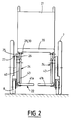
- Figure 2 is a front view, taken along line II-II of Figure 1 .
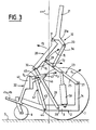
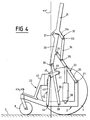
- Figures 3 and 4 are views similar to Figure 1 , illustrating the chair in two characteristic positions.
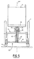
- Figure 5 is a front view similar to Figure 2 , but illustrating an alternative embodiment.
- FIGS. 1 and 2 schematically show a wheelchair 1 comprising a chassis 2 constituted by a lower frame 3 , for example formed by longitudinal members 4 joined by crosspieces 5 and 6 .
- the frame 2 is provided, usually in a known manner, wheels 7 generally carriers, and main drive and steering wheels 8, steerable by means of pivots 9.
- the wheels 8 are generally, but not necessarily, placed at the front part of the chassis 2 , while the carrying wheels 7 occupy the rear part.
- the wheels 7 and 8 define, by the points of contact with the ground S , a support or support polygon through the center of which passes a vertical axis x-x ' .
- the wheels 7 are mounted on the chassis 2 by means of bearings 10 and can advantageously be associated with motor members for reversible rotation drive 11 , such as one or more electric motors capable of being powered from a source 12 on board and arranged on a console 13 placed between uprights 14 .
- the chassis 2 conventionally supports an articulated structure comprising a seat 20 , a backrest 21 and a footrest 22 .
- the articulated structure is organized to be able to occupy a stable, folded state, corresponding to a so-called sitting position, as illustrated in FIG. 1 and a stable, unfolded state, corresponding to a verticalization position, such as illustrated in Figure 4 .
- the articulated structure is able to support a disabled or disabled person in a seated position and in a vertical position respectively.
- the articulated structure is organized so that the seat 20 is carried by the frame 2 by means of an articulation means 23 in the form of a deformable quadrilateral, such means being for example organized in two side assemblies 24 .
- Each assembly includes a rear articulated part or link 25 and a front articulated part or link 26 which are respectively mounted by pins 27 and 28 on the rear uprights 14 and on the side members 4 .
- the upper ends of the articulated parts or connecting rods 25 or 26 carry the seat 20 by means of articulation pins 29 and 30 which are respectively placed substantially in the middle part of the underside of the seat 20 and at the front part of the latter.
- the part 25 extends from the uprights 14 forward, in a substantially horizontal direction, while the front articulated part 26 also extends forward but in an upward inclination from chassis 2 .
- the backrest 21 is mounted, according to the invention, by a hinge pin 31 on the rear part of the seat 20 and is linked to the latter by a hinge means 32 in the form of a deformable quadrilateral.
- the means 32 comprises a movable part which is common to the deformable quadrilateral 23 .
- the means 32 is for example constituted by an extension 21a extending downward from the backrest 21 and on which is articulated, by an axis 33 , a movable part 34 , such as one or two links linked by an axis 35 at the rear part or parts 25 constituting the deformable quadrilateral 23 .
- the mobile part 34 can also be organized into two lateral assemblies in the same way as the assemblies 24 .
- the footrest 22 is preferably constituted by two legs 40 each provided at the base of a sole 41 .
- the two legs 40 are independent and devoid of articulation with the seat 20 and are carried by the chassis 2 by means of an articulation means 42 , of the deformable quadrilateral type, preferably also organized like the other quadrilaterals. in the form of two side assemblies.
- Each lateral assembly comprises a front part 43 articulated by an axis 44 on the chassis 2 and carrying the corresponding leg by an upper articulation axis 45 .
- Each lateral assembly also involves, for the constitution of the deformable quadrilateral, a common element with the deformable quadrilateral 23 , such a common element being constituted by the front part 26 which is, in such a case, located posterior to the front part 42 .
- the front part 26 is provided, below its point of articulation 30 with the seat 20 , of an extension 46 on which the leg 40 is mounted by means of a hinge pin. 47 .
- each deformable quadrilateral 42 extends forwardly in a rising inclination between the frame 2 and the leg 40 .
- the deformable quadrilateral system 23 is defined by the articulation points 27 , 28 , 29 and 30 .
- the deformable quadrilateral articulation system 32 is defined by the articulation points 29 , 31 , 33 and 35 .
- the articulation system based on a deformable quadrilateral 42 is defined by the articulation points 28 , 44, 45 and 47 .
- a drive member 50 making it possible to pass the articulated structure from the position according to FIG. 1 to the position according to FIG. 4 and vice versa.
- a drive member 50 may be constituted by a manually controlled mechanism or, preferably, by an energy transformer, of the electric jack type, capable of being supplied from the source 12 , in particular by means of a manipulator 51 accessible, for example on one of the removable or orientable armrests 52 , fitted to the backrest 21 or the seat 20 .
- the drive member 50 is interposed between the chassis 2 and one of the mobile elements of one of the deformable quadrilaterals and, preferably, that 23 specific to the seat 20 .
- the motor member 50 is constituted by an electric actuator whose base is adapted to the chassis 2 and whose rod is, for example, articulated by an axis 53 on a crosspiece connecting the parts 25 of the two side assemblies 24 .
- the frame 2 can be organized to show one or more stops 60 reserving a support for the articulated structure in position or in the folded state, cooperating for example directly or indirectly with the seat 20 and / or one of the appropriate deformable quadrilaterals.
- the articulated structure is in the folded position in a position such that the seat 20 is substantially horizontal and that the footrest 22 is located just in front of the front part of the chassis and the plane transverse of the articulation pivots of the steered wheels 8 .
- the motor member 50 When it is desired to control the change of state of the articulated structure to make it pass into a verticalization state, the motor member 50 is controlled, for example to ensure its extension stroke, so that it tends to lift the articulated elements 25 constituting the deformable quadrilateral 23 specific to the seat 20 .
- the articulated elements 25 are thus required to pivot in the direction of the arrow f 1 (fig. 3) on the axes 27 and cause the displacement of the axis 29 according to a circular trajectory T 1 having for its center the axis 29 and for radius the length of the elements 25 .
- the movement of the axis 29 leads in the same direction to the seat 20 , the hinge axis 30 of which is displaced along a circular trajectory T 2 having the axis 28 as its center and the length of the front part 26 as its radius.
- the constructive characteristics of the deformable quadrilateral 23 mean that the curves T 1 and T 2 intersect at a point O 1 , as illustrated in FIG. 3 , so that the seat moved backwards is simultaneously subjected to relative pivoting in the direction of the arrow f 2 .
- the pivoting of the seat 20 causes the upward movement of the axis 31 which subjects the backrest 21 to a relative movement relative to the seat, although remaining by itself substantially in the same inclination.
- Such a characteristic is provided by the structure of the deformable quadrilateral 32 .
- the displacement along the curve T 2 of the point 30 causes the displacement along the curve T 3 of the articulation point 47 of the deformable quadrilateral 42 , this trajectory T 3 having as its center the articulation point 28 and as its radius the link portion 26 between this point and axis 47 .
- the articulation points 45 are displaced along a circular path T 4 , having the axis 44 for center and the length of the front elements 42 for radius.
- the characteristics of the deformable quadrilaterals are chosen by construction so that, after the displacement of the drive member 50 on its active stroke, the seat 20 and the backrest 21 are substantially placed in alignment at a slight inclination, while the feet 22 is located by back-displacement included inside the support polygon defined by the wheels 7 and 8 . In this so-called verticalization state, as shown in FIG.
- the constructive characteristic of the support and articulation means based on three deformable quadrilaterals has the characteristic of causing the relative displacement of the backrest, the seat and the footrest, along the paths T 1 , T 2 , T 3 and T 4 which are directed towards the rear part of the chair and thus generate a retro-displacement of the articulated structure to bring the latter from the sitting position with an anterior tendency to a vertical position substantially centered on the axis x-x ' .
- the means according to the invention make it possible to significantly reduce the bulk in the anteroposterior plane of the chair in a vertical position and to give it in this state a compactness favoring the evolutions.
- FIG. 5 shows an alternative embodiment in which the deformable quadrilaterals are no longer organized in lateral assemblies such as 24 , but in the form of a column being grouped on either side of the anteroposterior plane of vertical symmetry P-P ' .
- the invention finds a particularly interesting industrial application in the standing chairs which, moreover, offer a possibility of folding along a vertical, longitudinal plane of symmetry, so as to reduce it congestion in the transport phases, in particular in the automobile.
Landscapes
- Health & Medical Sciences (AREA)
- Life Sciences & Earth Sciences (AREA)
- Animal Behavior & Ethology (AREA)
- General Health & Medical Sciences (AREA)
- Public Health (AREA)
- Veterinary Medicine (AREA)
- Handcart (AREA)
- Escalators And Moving Walkways (AREA)
- Fittings On The Vehicle Exterior For Carrying Loads, And Devices For Holding Or Mounting Articles (AREA)
Description
- l'assise et le repose-pieds ne présentent aucune articulation directe l'un avec l'autre, et sont montés sur les extrémités supérieures de deux quadrilatères déformables, s'élevant à partir du châssis et possédant une partie mobile commune,
- les moyens de commande en élévation-abaissement comprennent un organe moteur interposé entre le châssis et l'un des organes mobiles de l'un des quadrilatères et apte à commander le déplacement desdits quadrilatères entre un état stable replié correspondant à une position dite assise de la structure et un état stable déplié correspondant à une position dite de verticalisation de la structure dans laquelle la masse que représente cette dernière est sensiblement centrée par rapport au polygone d'appui.
Claims (9)
- Dispositif-élévateur pour fauteuil roulant verticalisateur, du type comportant un châssis (2) muni de roues (7, 8) définissant un polygone d'appui et supportant une structure articulée comprenant une assise (20), un repose-pieds (22) et un dossier (21), dispositif comprenant des moyens de support et d'articulation de la structure sur le châssis et des moyens de commande en élévation-abaissement de ladite structure par rapport au châssis,
caractérisé en ce quel'assise et le repose-pieds ne présentent aucune articulation directe l'un avec l'autre, et sont montés sur les extrémités supérieures de deux quadrilatères déformables (23, 42), s'élevant à partir du châssis et possédant une partie mobile commune (26),les moyens (50) de commande en élévation-abaissement comprennent un organe moteur interposé entre le châssis et l'un des organes mobiles de l'un des quadrilatères et apte à commander le déplacement desdits quadrilatères entre un état stable replié correspondant à une position dite assise de la structure et un état stable déplié correspondant à une position dite de verticalisation de la structure dans laquelle la masse que représente cette dernière est sensiblement centrée par rapport au polygone d'appui. - Dispositif-élévateur selon la revendication 1, caractérisé en ce que la structure comprend un repose-pieds (22), une assise (20) et un dossier (21) articulé par sa base sur la partie postérieure de l'assise et lié par un quadrilatère déformable (32) à celui de l'assise avec lequel il comporte une partie mobile commune (25).
- Dispositif-élévateur selon la revendication 1 ou 2, caractérisé en ce que la structure articulée est montée sur le châssis par des quadrilatères déformables qui sont organisés en deux ensembles latéraux (24).
- Dispositif-élévateur selon la revendication 1 ou 2, caractérisé en ce que la structure articulée est montée sur le châssis par des quadrilatères déformables qui sont organisés sous la forme d'une colonne.
- Dispositif-élévateur selon l'une des revendications 1 à 4, caractérisé en ce que la structure comprend une assise (20) qui est montée articulée par sa partie antérieure et sensiblement par sa partie médiane sur les extrémités supérieures des parties mobiles (25, 26) constitutives des quadrilatères et respectivement dites avant et arrière et liées à la partie inférieure (3) et à la partie arrière (14) du châssis.
- Dispositif-élévateur selon l'une des revendications 1 à 5, caractérisé en ce que la structure comprend un repose-pieds (22) qui est monté articulé d'une part, au niveau d'une partie arrière, sur la partie mobile dite "avant" (26) du quadrilatère déformable (23) et, d'autre part, en avant de cette partie arrière, sur une partie mobile antérieure (43) constitutive du quadrilatère déformable (42) elle même articulée sur la partie inférieure du chassis
- Dispositif-élévateur selon l'une des revendications 1 à 6, caractérisé en ce que l'organe moteur (50) est constitué par un transformateur d'énergie interposé entre le châssis (2) et le quadrilatère (23) propre à l'assise.
- Dispositif-élévateur selon l'une des revendications 1 à 6, caractérisé en ce que l'organe moteur (50) est constitué par un moyen à commande manuelle associé à au moins un compensateur élastique.
- Fauteuil roulant verticalisateur comportant une structure articulée liée au châssis par un dispositif-élévateur selon l'une des revendications 1 à 8.
Applications Claiming Priority (3)
| Application Number | Priority Date | Filing Date | Title |
|---|---|---|---|
| FR9403439A FR2717377B1 (fr) | 1994-03-18 | 1994-03-18 | Dispositif-élévateur pour fauteuil roulant verticalisateur et fauteuil roulant en faisant application. |
| FR9403439 | 1994-03-18 | ||
| PCT/FR1995/000330 WO1995025497A1 (fr) | 1994-03-18 | 1995-03-17 | Dispositif-elevateur pour fauteuil roulant verticalisateur et fauteuil roulant en faisant application |
Publications (2)
| Publication Number | Publication Date |
|---|---|
| EP0699067A1 EP0699067A1 (fr) | 1996-03-06 |
| EP0699067B1 true EP0699067B1 (fr) | 1998-09-16 |
Family
ID=9461366
Family Applications (1)
| Application Number | Title | Priority Date | Filing Date |
|---|---|---|---|
| EP95913214A Expired - Lifetime EP0699067B1 (fr) | 1994-03-18 | 1995-03-17 | Dispositif-elevateur pour fauteuil roulant verticalisateur et fauteuil roulant en faisant application |
Country Status (7)
| Country | Link |
|---|---|
| US (1) | US5772226A (fr) |
| EP (1) | EP0699067B1 (fr) |
| AT (1) | ATE171061T1 (fr) |
| CA (1) | CA2163254A1 (fr) |
| DE (1) | DE69504790T2 (fr) |
| FR (1) | FR2717377B1 (fr) |
| WO (1) | WO1995025497A1 (fr) |
Cited By (1)
| Publication number | Priority date | Publication date | Assignee | Title |
|---|---|---|---|---|
| CN105832474A (zh) * | 2016-03-10 | 2016-08-10 | 国家康复辅具研究中心 | 辅助站立装置 |
Families Citing this family (77)
| Publication number | Priority date | Publication date | Assignee | Title |
|---|---|---|---|---|
| US6176335B1 (en) * | 1996-07-03 | 2001-01-23 | Pride Mobility Products, Corporation | Power wheelchair |
| US6276704B1 (en) * | 1997-09-23 | 2001-08-21 | Charles J. Suiter | Adjustable wheelchair having a tilting and reclining seat |
| US5971482A (en) * | 1997-10-02 | 1999-10-26 | Invacare Corporation | Constant center of gravity tiltable chair of a wheelchair |
| US6125957A (en) * | 1998-02-10 | 2000-10-03 | Kauffmann; Ricardo M. | Prosthetic apparatus for supporting a user in sitting or standing positions |
| US6126186A (en) * | 1998-11-09 | 2000-10-03 | Invacare Corporation | Constant center of gravity tilt seat of a wheelchair |
| DE19912840B4 (de) * | 1999-03-10 | 2004-07-22 | I.D.C. Medical | Hebestuhl für Behinderte und Invalide |
| US6192533B1 (en) | 1999-04-02 | 2001-02-27 | I.D.C. Medical | Elevator chairs for the handicapped and invalids |
| US6343805B1 (en) * | 1999-09-27 | 2002-02-05 | Richard A. Roy | Folding wheelchair |
| USD431502S (en) * | 2000-03-27 | 2000-10-03 | Kurt Manufacturing Company | Wheelchair with vertically adjustable seat |
| WO2001087219A1 (fr) * | 2000-05-18 | 2001-11-22 | Borringia Industrie Ag | Chaise pour personnes handicapees |
| FR2813520B1 (fr) * | 2000-09-07 | 2002-12-06 | Idc Medical | Dispositif de maintien corporel pour fauteuil verticalisateur et fauteuil en faisant application |
| US6554086B1 (en) | 2000-10-27 | 2003-04-29 | Invacare Corporation | Obstacle traversing wheelchair |
| US6611975B1 (en) * | 2001-02-23 | 2003-09-02 | Roy D. Ricketts | Motorized bed assembly |
| GB2380399B (en) * | 2001-04-03 | 2005-02-02 | Graham Taylor | A powered lift recliner chair |
| US6619681B2 (en) | 2001-05-16 | 2003-09-16 | Delano Association For The Developmentally Disabled | Dynamic seating and walking wheelchair |
| US6578854B2 (en) * | 2001-07-30 | 2003-06-17 | Solorider Industries, Inc. | Personal mobility vehicle incorporating tilting and swiveling seat and method for use while playing golf |
| CH694982A5 (de) * | 2001-09-21 | 2005-10-31 | Levo Ag | Aufrichtrollstuhl. |
| US7040429B2 (en) | 2001-10-10 | 2006-05-09 | Invacare Corporation | Wheelchair suspension |
| US7066290B2 (en) | 2001-10-19 | 2006-06-27 | Invacare Corp. | Wheelchair suspension having pivotal motor mount |
| US11213441B2 (en) | 2002-10-25 | 2022-01-04 | Invacare Corporation | Suspension for wheeled vehicles |
| US7293801B2 (en) | 2003-08-18 | 2007-11-13 | Invacare Corporation | Self-stabilizing suspension for wheeled vehicles |
| US7104346B2 (en) * | 2003-03-25 | 2006-09-12 | Schaffner Walter E | Power wheelchair |
| US6976698B2 (en) * | 2003-04-24 | 2005-12-20 | Rehabilitation Institute Of Chicago | Manually operable standing wheelchair |
| EP1506760A1 (fr) * | 2003-08-15 | 2005-02-16 | Pride Mobility Products, Corporation | Mécanismes de levage et d'inclinaison, maintenant un centre de gravité constant, pour un siège de fauteuil roulant |
| US7296856B2 (en) | 2003-10-08 | 2007-11-20 | Pride Mobility Products Corporation | Reclining seat with movable back support |
| US7097189B2 (en) * | 2003-11-18 | 2006-08-29 | Lloyd Linden, Inc. | Wheelchair with self-raising seat |
| KR100805743B1 (ko) | 2004-03-08 | 2008-02-21 | 재단법인 산재의료관리원 | 전동 기립형 휠체어 |
| AU2005277594A1 (en) | 2004-08-16 | 2006-03-02 | Hill-Rom Services, Inc. | Chair |
| EP1802219A2 (fr) * | 2004-08-16 | 2007-07-04 | Kenneth L. Kramer | Equipement pour soins a domicile |
| EP1791509A1 (fr) * | 2004-09-03 | 2007-06-06 | John Joseph Meaney | Appareil pour aider une personne à passer entre une position sensiblement levée et une position assise |
| CA2523067C (fr) * | 2004-10-12 | 2013-03-12 | Altimate Medical, Inc. | Orthopodium modulaire |
| CA2601470C (fr) * | 2005-03-30 | 2014-09-23 | Jaimie Borisoff | Fauteil roulant a hauteur reglable |
| US7051383B1 (en) * | 2005-05-17 | 2006-05-30 | Ohad Paz | Powered lift toilet seat |
| US8210295B2 (en) * | 2005-05-30 | 2012-07-03 | Yoshisuke Kuramoto | Electric wheelchair |
| US20060279129A1 (en) * | 2005-06-09 | 2006-12-14 | Kraft Clifford H | Safety improvement for restraint free ambulation device |
| DE102005038030B4 (de) * | 2005-08-08 | 2007-08-09 | Otto Bock Healthcare Ip Gmbh & Co. Kg | Aufrichtrollstuhl |
| DE102005038029B3 (de) * | 2005-08-08 | 2006-11-09 | Otto Bock Healthcare Ip Gmbh & Co. Kg | Aufrichtrollstuhl |
| FR2890855B1 (fr) | 2005-09-20 | 2007-12-14 | Lifestand Vivre Debout Soc Res | Siege verticalisateur a moyens de reglage de l'inclinaison du repose-pieds en position verticalisee. |
| US7472920B2 (en) * | 2006-01-23 | 2009-01-06 | Chang-Wei Chai | Retractable bed mechanism |
| JP2007244817A (ja) * | 2006-03-15 | 2007-09-27 | Tc Lab:Kk | 昇降機能を備えた電動車椅子 |
| FR2901997B1 (fr) * | 2006-06-07 | 2009-05-15 | Lifestand Vivre Debout Soc A R | Siege verticalisateur a dossier inclinable |
| EP1943995A1 (fr) | 2007-01-12 | 2008-07-16 | Invacare International Sàrl | Moyen de transport sur roues doté de bras de suspension pour les roues |
| US8104554B2 (en) * | 2007-02-07 | 2012-01-31 | Graham Randall J | Device for transporting a physically impaired person |
| ATE493960T1 (de) * | 2007-02-08 | 2011-01-15 | Invacare Corp | Rollstuhlaufhängung |
| DK2340800T3 (da) | 2007-02-14 | 2013-07-22 | Invacare Corp | Stabilitetsstyringssystem |
| US7802846B2 (en) * | 2007-03-19 | 2010-09-28 | Pierre Bellefleur | Reclining chair and chassis, frame and kit therefor |
| DE102007014680B4 (de) * | 2007-03-27 | 2009-06-18 | Pihsiang Machinery Manufacturing Co., Ltd., Sinfong | Klappbarer, elektrischer Rollstuhl |
| CH712922B1 (de) | 2007-07-13 | 2018-03-15 | Levo Ag Wohlen | Aufrichteinheit für Aufrichtrollstühle und Therapiegeräte. |
| US20090121965A1 (en) * | 2007-11-13 | 2009-05-14 | Atmel Corporation | Spherical antenna |
| US8123664B2 (en) | 2008-01-22 | 2012-02-28 | Invacare Corp. | Seat |
| DE102008013246A1 (de) | 2008-03-08 | 2009-09-10 | Schaeffler Kg | Transportvorrichtung für Patienten |
| US8104835B2 (en) * | 2008-07-08 | 2012-01-31 | Invacare Corp. | Standing frame with supine mode |
| TWM355257U (en) * | 2008-10-17 | 2009-04-21 | Peterson Internat Corp | Auxiliary supporting apparatus for sitting and standing |
| US20110025463A1 (en) * | 2009-08-03 | 2011-02-03 | Atmel Corporation | Parallel Antennas for Contactless Device |
| EP3238682A3 (fr) | 2009-10-09 | 2018-01-10 | Invacare Corporation | Suspension de chaise roulante avec mouvement opposé du bras antibasculements |
| EP2608757A4 (fr) * | 2010-08-24 | 2015-05-06 | Univ New York State Res Found | Appareil portable à six barres pour le levage, l'abaissement, et le déplacement auto-propulsé |
| RU2484803C1 (ru) * | 2012-02-08 | 2013-06-20 | Николай Петрович Дядченко | Шасси двухколесное кресла-коляски |
| NZ628837A (en) | 2012-02-15 | 2016-10-28 | Invacare Corp | Wheelchair suspension |
| DE102012102699B4 (de) * | 2012-03-29 | 2013-10-17 | medica - Medizintechnik GmbH | Aufstehtrainer |
| US9351890B2 (en) | 2013-03-15 | 2016-05-31 | Stryker Corporation | Medical support apparatus |
| US9060911B2 (en) | 2013-09-24 | 2015-06-23 | Elwha Llc | Systems, devices, and methods including a stand-up wheel chair having automatic stability control |
| CH709358A1 (de) * | 2014-03-04 | 2015-09-15 | Levo Ag Wohlen | Aufrichtrollstuhl. |
| AU2015290001B2 (en) * | 2014-07-14 | 2018-07-26 | Exokinetics, Inc. | Elevating walker chair |
| CN105287123B (zh) * | 2015-11-20 | 2017-03-22 | 合肥工业大学 | 一种康复轮椅 |
| US11020295B2 (en) | 2015-12-22 | 2021-06-01 | Stryker Corporation | Patient support systems and methods for assisting caregivers with patient care |
| US9849050B2 (en) * | 2016-02-25 | 2017-12-26 | Judie McClean | Wheelchair lift assembly |
| EP3243492B1 (fr) | 2016-05-09 | 2019-02-13 | 4 Power 4 | Fauteuil roulant de verticalisation a trajectoire retro-verticalisante-descendante du repose-pieds |
| US10813806B2 (en) | 2016-05-24 | 2020-10-27 | Stryker Corporation | Medical support apparatus with stand assistance |
| US11607360B2 (en) * | 2017-08-19 | 2023-03-21 | Bala R. Vatti | Multi-function adaptable lift system |
| US11173084B2 (en) | 2017-11-09 | 2021-11-16 | Dowding Tool Products Llc | Sit-to-stand wheelchair |
| CN110123053B (zh) * | 2019-01-11 | 2022-05-31 | 申秀巧 | 一种用于坐躺装置的收放机构 |
| AU2020243458A1 (en) * | 2019-03-18 | 2021-08-26 | Motion Concepts L.P. | Suspension system for power wheelchair stander |
| EP3711832A1 (fr) * | 2019-03-22 | 2020-09-23 | Bolliger & Mabillard, Ingenieurs Conseils S.A. | Système de maintien de passager pour montagnes russes |
| US11833089B2 (en) * | 2019-11-19 | 2023-12-05 | Dowding Tool Products Llc | Sit-to-stand wheelchair |
| US11903887B2 (en) | 2020-02-25 | 2024-02-20 | Invacare Corporation | Wheelchair and suspension systems |
| JP7340857B2 (ja) * | 2020-03-23 | 2023-09-08 | カネタコーポレーション株式会社 | 移乗装置 |
| WO2023019113A2 (fr) * | 2021-08-11 | 2023-02-16 | Kevin Ferguson | Tabouret d'atelier motorisé avec mécanisme d'agenouillement |
Citations (1)
| Publication number | Priority date | Publication date | Assignee | Title |
|---|---|---|---|---|
| WO1982001314A1 (fr) * | 1980-10-21 | 1982-04-29 | Roger Churchward | Chaise a postures multiples specialement chaise roulante, avec des moyens pour aider l'utilisateur a se lever |
Family Cites Families (11)
| Publication number | Priority date | Publication date | Assignee | Title |
|---|---|---|---|---|
| GB468686A (en) * | 1935-12-06 | 1937-07-06 | Ig Farbenindustrie Ag | Improvements in the manufacture and production of vat dyestuffs of the anthraquinone series |
| US3882949A (en) * | 1972-11-16 | 1975-05-13 | Us Health | Universal wheelchair for the severely disabled |
| US4231614A (en) * | 1978-10-27 | 1980-11-04 | Shaffer Gene P | Wheelchair |
| US4456086A (en) * | 1979-08-01 | 1984-06-26 | The United States Of America As Represented By The Secretary Of The Navy | Integrated wheelchair and ambulator |
| FR2545718B1 (fr) * | 1983-05-10 | 1986-07-11 | Int Diffusion Consomma | Dispositif de maintien corporel pour fauteuil de handicape comportant une structure de verticalisation |
| US4569556A (en) * | 1983-12-29 | 1986-02-11 | Societe A Responsabilite Limitee International Diffusion Consommateur I.D.C | Elevator device for wheelchair and wheelchair incorporating same |
| US4809804A (en) * | 1986-08-25 | 1989-03-07 | Falcon Rehabilitation Products, Inc. | Combination wheelchair and walker apparatus |
| US5312153A (en) * | 1990-07-23 | 1994-05-17 | Ortho-Kinetics, Inc. | Recline lift wall hugger chair |
| US5219204A (en) * | 1990-10-15 | 1993-06-15 | Bathrick Leeland M | Recliner and elevator chair |
| US5203610A (en) * | 1990-11-14 | 1993-04-20 | Invacare Corporation | Reclining lift chair having wheels for transport |
| US5346280A (en) * | 1992-03-31 | 1994-09-13 | Deumite Norman A | Chair with automatic standing aid |
-
1994
- 1994-03-18 FR FR9403439A patent/FR2717377B1/fr not_active Expired - Lifetime
-
1995
- 1995-03-17 WO PCT/FR1995/000330 patent/WO1995025497A1/fr not_active Ceased
- 1995-03-17 EP EP95913214A patent/EP0699067B1/fr not_active Expired - Lifetime
- 1995-03-17 CA CA002163254A patent/CA2163254A1/fr not_active Abandoned
- 1995-03-17 US US08/545,569 patent/US5772226A/en not_active Expired - Lifetime
- 1995-03-17 DE DE69504790T patent/DE69504790T2/de not_active Expired - Lifetime
- 1995-03-17 AT AT95913214T patent/ATE171061T1/de not_active IP Right Cessation
Patent Citations (1)
| Publication number | Priority date | Publication date | Assignee | Title |
|---|---|---|---|---|
| WO1982001314A1 (fr) * | 1980-10-21 | 1982-04-29 | Roger Churchward | Chaise a postures multiples specialement chaise roulante, avec des moyens pour aider l'utilisateur a se lever |
Cited By (1)
| Publication number | Priority date | Publication date | Assignee | Title |
|---|---|---|---|---|
| CN105832474A (zh) * | 2016-03-10 | 2016-08-10 | 国家康复辅具研究中心 | 辅助站立装置 |
Also Published As
| Publication number | Publication date |
|---|---|
| CA2163254A1 (fr) | 1995-09-28 |
| DE69504790T2 (de) | 1999-03-18 |
| FR2717377B1 (fr) | 1996-06-21 |
| ATE171061T1 (de) | 1998-10-15 |
| US5772226A (en) | 1998-06-30 |
| WO1995025497A1 (fr) | 1995-09-28 |
| DE69504790D1 (de) | 1998-10-22 |
| EP0699067A1 (fr) | 1996-03-06 |
| FR2717377A1 (fr) | 1995-09-22 |
Similar Documents
| Publication | Publication Date | Title |
|---|---|---|
| EP0699067A1 (fr) | Dispositif-elevateur pour fauteuil roulant verticalisateur et fauteuil roulant en faisant application | |
| EP1764070B1 (fr) | Siege verticalisateur a moyens de reglage de l'inclinaison du repose-pieds en position verticalisee. | |
| EP1864637B1 (fr) | Siege verticalisateur à dossier inclinable | |
| EP2004124B1 (fr) | Fauteuil multipositions pour handicape | |
| CA2181439C (fr) | Siege roulant pour le transport ou l'assistance au deplacement d'au moins un utilisateur, notamment d'une personne handicapee | |
| EP0059141B1 (fr) | Fauteuil roulant permettant le redressement de son utilisateur | |
| EP0588735A1 (fr) | Dispositif d'assistance motorisée, adaptable sur un fauteuil-élévateur et fauteil-élévateur en faisant application | |
| WO2018154234A1 (fr) | Fauteuil roulant d'aide à la marche | |
| EP0146660B1 (fr) | Dispositif élévateur pour fauteuil roulant et fauteuil roulant en faisant application | |
| FR2529456A1 (fr) | Dispositif elevateur pour fauteuil roulant et fauteuil roulant en faisant application | |
| EP3243492B1 (fr) | Fauteuil roulant de verticalisation a trajectoire retro-verticalisante-descendante du repose-pieds | |
| EP1488770B1 (fr) | Fauteuil verticalisateur à modification automatique de l'inclinaison du dossier | |
| EP0495862B1 (fr) | Leve-malade | |
| FR2769830A1 (fr) | Perfectionnements aux fauteuils elevateurs pour handicapes et invalides | |
| WO2018104595A1 (fr) | Dispositif d'appui antérieur pour les membres inférieurs | |
| FR2915091A1 (fr) | Fauteuil verticalisateur a garde au sol du repose-pied variable | |
| EP0959860A1 (fr) | Accessoire pour fauteuil roulant destine a le maintenir en une position stable de relaxation | |
| EP0231718A1 (fr) | Fauteuil roulant pliant et élévateur | |
| FR2710275A1 (fr) | Dispositif de fauteuil à ski. | |
| FR2784022A1 (fr) | Ensemble utilitaire pour personnes a mobilite reduite | |
| FR2619495A1 (fr) | Chaise longue | |
| FR3079119A1 (fr) | Dispositif d’aide au passage de la position assise a la position debout, et inversement, plateforme de mobilite pour siege comprenant un tel dispositif, et siege roulant | |
| FR2712802A1 (fr) | Fauteuil élévateur motorisé. | |
| FR2784292A1 (fr) | Ensemble utilitaire pour personnes a mobilite reduite | |
| FR2872029A1 (fr) | Vehicule automobile pour personne a mobilite reduite |
Legal Events
| Date | Code | Title | Description |
|---|---|---|---|
| PUAI | Public reference made under article 153(3) epc to a published international application that has entered the european phase |
Free format text: ORIGINAL CODE: 0009012 |
|
| 17P | Request for examination filed |
Effective date: 19951104 |
|
| AK | Designated contracting states |
Kind code of ref document: A1 Designated state(s): AT BE CH DE DK ES GB GR IE IT LI LU MC NL PT SE |
|
| 17Q | First examination report despatched |
Effective date: 19970227 |
|
| GRAG | Despatch of communication of intention to grant |
Free format text: ORIGINAL CODE: EPIDOS AGRA |
|
| GRAG | Despatch of communication of intention to grant |
Free format text: ORIGINAL CODE: EPIDOS AGRA |
|
| GRAH | Despatch of communication of intention to grant a patent |
Free format text: ORIGINAL CODE: EPIDOS IGRA |
|
| GRAH | Despatch of communication of intention to grant a patent |
Free format text: ORIGINAL CODE: EPIDOS IGRA |
|
| GRAA | (expected) grant |
Free format text: ORIGINAL CODE: 0009210 |
|
| AK | Designated contracting states |
Kind code of ref document: B1 Designated state(s): AT BE CH DE DK ES GB GR IE IT LI LU MC NL PT SE |
|
| PG25 | Lapsed in a contracting state [announced via postgrant information from national office to epo] |
Ref country code: NL Free format text: LAPSE BECAUSE OF FAILURE TO SUBMIT A TRANSLATION OF THE DESCRIPTION OR TO PAY THE FEE WITHIN THE PRESCRIBED TIME-LIMIT Effective date: 19980916 Ref country code: IT Free format text: LAPSE BECAUSE OF FAILURE TO SUBMIT A TRANSLATION OF THE DESCRIPTION OR TO PAY THE FEE WITHIN THE PRESCRIBED TIME-LIMIT;WARNING: LAPSES OF ITALIAN PATENTS WITH EFFECTIVE DATE BEFORE 2007 MAY HAVE OCCURRED AT ANY TIME BEFORE 2007. THE CORRECT EFFECTIVE DATE MAY BE DIFFERENT FROM THE ONE RECORDED. Effective date: 19980916 Ref country code: GR Free format text: LAPSE BECAUSE OF NON-PAYMENT OF DUE FEES Effective date: 19980916 Ref country code: ES Free format text: THE PATENT HAS BEEN ANNULLED BY A DECISION OF A NATIONAL AUTHORITY Effective date: 19980916 Ref country code: AT Free format text: LAPSE BECAUSE OF FAILURE TO SUBMIT A TRANSLATION OF THE DESCRIPTION OR TO PAY THE FEE WITHIN THE PRESCRIBED TIME-LIMIT Effective date: 19980916 |
|
| REF | Corresponds to: |
Ref document number: 171061 Country of ref document: AT Date of ref document: 19981015 Kind code of ref document: T |
|
| REG | Reference to a national code |
Ref country code: CH Ref legal event code: EP |
|
| REF | Corresponds to: |
Ref document number: 69504790 Country of ref document: DE Date of ref document: 19981022 |
|
| GBT | Gb: translation of ep patent filed (gb section 77(6)(a)/1977) |
Effective date: 19981106 |
|
| REG | Reference to a national code |
Ref country code: IE Ref legal event code: FG4D Free format text: FRENCH |
|
| PG25 | Lapsed in a contracting state [announced via postgrant information from national office to epo] |
Ref country code: DK Free format text: LAPSE BECAUSE OF FAILURE TO SUBMIT A TRANSLATION OF THE DESCRIPTION OR TO PAY THE FEE WITHIN THE PRESCRIBED TIME-LIMIT Effective date: 19981216 |
|
| PG25 | Lapsed in a contracting state [announced via postgrant information from national office to epo] |
Ref country code: PT Free format text: LAPSE BECAUSE OF FAILURE TO SUBMIT A TRANSLATION OF THE DESCRIPTION OR TO PAY THE FEE WITHIN THE PRESCRIBED TIME-LIMIT Effective date: 19981218 |
|
| REG | Reference to a national code |
Ref country code: CH Ref legal event code: NV Representative=s name: BOVARD AG PATENTANWAELTE |
|
| NLV1 | Nl: lapsed or annulled due to failure to fulfill the requirements of art. 29p and 29m of the patents act | ||
| PG25 | Lapsed in a contracting state [announced via postgrant information from national office to epo] |
Ref country code: LU Free format text: LAPSE BECAUSE OF NON-PAYMENT OF DUE FEES Effective date: 19990317 |
|
| PG25 | Lapsed in a contracting state [announced via postgrant information from national office to epo] |
Ref country code: BE Free format text: LAPSE BECAUSE OF NON-PAYMENT OF DUE FEES Effective date: 19990331 |
|
| PG25 | Lapsed in a contracting state [announced via postgrant information from national office to epo] |
Ref country code: IE Free format text: LAPSE BECAUSE OF NON-PAYMENT OF DUE FEES Effective date: 19990504 |
|
| REG | Reference to a national code |
Ref country code: IE Ref legal event code: FD4D |
|
| PLBE | No opposition filed within time limit |
Free format text: ORIGINAL CODE: 0009261 |
|
| STAA | Information on the status of an ep patent application or granted ep patent |
Free format text: STATUS: NO OPPOSITION FILED WITHIN TIME LIMIT |
|
| 26N | No opposition filed | ||
| BERE | Be: lapsed |
Owner name: S.A. INTERNATIONAL DIFFUSION CONSOMMATEURS IDC Effective date: 19990331 |
|
| PG25 | Lapsed in a contracting state [announced via postgrant information from national office to epo] |
Ref country code: MC Free format text: LAPSE BECAUSE OF NON-PAYMENT OF DUE FEES Effective date: 19990930 |
|
| REG | Reference to a national code |
Ref country code: GB Ref legal event code: IF02 |
|
| REG | Reference to a national code |
Ref country code: CH Ref legal event code: PFA Owner name: INTERNATIONAL DIFFUSION CONSOMMATEURS (I.D.C.) SO Free format text: INTERNATIONAL DIFFUSION CONSOMMATEURS (I.D.C.) SOCIETE ANONYME:#QUARTIER BASSES BLACHES, GARE DE MARCHES#F-26300 BOURG DE PEAGE (FR) -TRANSFER TO- INTERNATIONAL DIFFUSION CONSOMMATEURS (I.D.C.) SOCIETE ANONYME:#QUARTIER BASSES BLACHES, GARE DE MARCHES#F-26300 BOURG DE PEAGE (FR) |
|
| PGFP | Annual fee paid to national office [announced via postgrant information from national office to epo] |
Ref country code: DE Payment date: 20140311 Year of fee payment: 20 Ref country code: SE Payment date: 20140313 Year of fee payment: 20 Ref country code: CH Payment date: 20140313 Year of fee payment: 20 |
|
| PGFP | Annual fee paid to national office [announced via postgrant information from national office to epo] |
Ref country code: GB Payment date: 20140317 Year of fee payment: 20 |
|
| REG | Reference to a national code |
Ref country code: DE Ref legal event code: R071 Ref document number: 69504790 Country of ref document: DE |
|
| REG | Reference to a national code |
Ref country code: CH Ref legal event code: PL |
|
| REG | Reference to a national code |
Ref country code: GB Ref legal event code: PE20 Expiry date: 20150316 |
|
| REG | Reference to a national code |
Ref country code: SE Ref legal event code: EUG |
|
| PG25 | Lapsed in a contracting state [announced via postgrant information from national office to epo] |
Ref country code: GB Free format text: LAPSE BECAUSE OF EXPIRATION OF PROTECTION Effective date: 20150316 |