EP0699107B1 - Procede pour reguler le debit de sortie d'un liquide separe dans un separateur centrifuge et separateur centrifuge de mise en oeuvre du procede - Google Patents
Procede pour reguler le debit de sortie d'un liquide separe dans un separateur centrifuge et separateur centrifuge de mise en oeuvre du procede Download PDFInfo
- Publication number
- EP0699107B1 EP0699107B1 EP94916468A EP94916468A EP0699107B1 EP 0699107 B1 EP0699107 B1 EP 0699107B1 EP 94916468 A EP94916468 A EP 94916468A EP 94916468 A EP94916468 A EP 94916468A EP 0699107 B1 EP0699107 B1 EP 0699107B1
- Authority
- EP
- European Patent Office
- Prior art keywords
- outlet
- outlet chamber
- liquid
- rotor
- chamber
- Prior art date
- Legal status (The legal status is an assumption and is not a legal conclusion. Google has not performed a legal analysis and makes no representation as to the accuracy of the status listed.)
- Expired - Lifetime
Links
- 239000007788 liquid Substances 0.000 title claims description 108
- 238000000034 method Methods 0.000 title claims description 10
- 230000001105 regulatory effect Effects 0.000 title claims description 7
- 238000000926 separation method Methods 0.000 claims description 24
- 230000010355 oscillation Effects 0.000 description 2
- 230000002093 peripheral effect Effects 0.000 description 2
- 238000011084 recovery Methods 0.000 description 2
- 239000000126 substance Substances 0.000 description 1
Images
Classifications
-
- B—PERFORMING OPERATIONS; TRANSPORTING
- B04—CENTRIFUGAL APPARATUS OR MACHINES FOR CARRYING-OUT PHYSICAL OR CHEMICAL PROCESSES
- B04B—CENTRIFUGES
- B04B1/00—Centrifuges with rotary bowls provided with solid jackets for separating predominantly liquid mixtures with or without solid particles
- B04B1/04—Centrifuges with rotary bowls provided with solid jackets for separating predominantly liquid mixtures with or without solid particles with inserted separating walls
- B04B1/08—Centrifuges with rotary bowls provided with solid jackets for separating predominantly liquid mixtures with or without solid particles with inserted separating walls of conical shape
-
- B—PERFORMING OPERATIONS; TRANSPORTING
- B04—CENTRIFUGAL APPARATUS OR MACHINES FOR CARRYING-OUT PHYSICAL OR CHEMICAL PROCESSES
- B04B—CENTRIFUGES
- B04B1/00—Centrifuges with rotary bowls provided with solid jackets for separating predominantly liquid mixtures with or without solid particles
- B04B1/10—Centrifuges with rotary bowls provided with solid jackets for separating predominantly liquid mixtures with or without solid particles with discharging outlets in the plane of the maximum diameter of the bowl
- B04B1/14—Centrifuges with rotary bowls provided with solid jackets for separating predominantly liquid mixtures with or without solid particles with discharging outlets in the plane of the maximum diameter of the bowl with periodical discharge
Definitions
- the present invention concerns a method of regulating during operation the outlet flow of a liquid separated in a separation chamber in a rotor of a centrifugal separator, the rotor being rotatable around the rotational axis in a predetermined rotational direction, in which method the separated liquids is conducted into an outlet chamber to form therein a rotating liquid body with a radially inwardly directed free liquid surface, and is discharged out of the outlet chamber through a stationary discharge device having at least one internal outlet channel with an inlet opening in a radially outer part of the outlet device which, during operation, is located radially outside the free liquid surface.
- the invention concerns a centrifugal separator, in which the outlet flow of a separated liquid is regulated according to this method.
- a centrifugal separator comprises a rotor, which is rotatable around a rotational axis in a predetermined direction and forms an inlet chamber for a liquid to be centrifugally treated, a separation chamber connected to the inlet chamber, and an outlet chamber delimited axially by two end walls and radially by a circumferential wall connecting the end walls, the outlet chamber being so arranged that, during operation, a liquid separated in the separation chamber passes into the outlet chamber and forms therein a liquid rotating body having a radially inwardly directed free liquid surface.
- the outlet chamber is connected to the separation chamber by a connection through one of said end walls, this connection having an opening in the outlet chamber located radially inside the radial level of the free liquid surface.
- the centrifugal separator also comprises a stationary discharge device, which is arranged in the outlet chamber and has at least one outlet channel connected to an outlet and having an inlet opening at a part of the discharge device which is located radially outside the free liquid surface.
- a centrifugal separator of this kind is shown in WO 89/03250.
- the liquid present in the outlet chamber is entrained gently to rotate with the rotor by means of discs arranged in the outlet chamber.
- the separated liquid is discharged out of the outlet chamber through a stationary discharge device arranged therein and connected to a liquid outlet.
- the flow of the discharged liquid depends on the angular speed of the rotating liquid in the outlet chamber, the radial position of the free liquid surface, the design of the discharge device, and the prevailing counter-pressure in the outlet for the liquid.
- a discharge device For every specific use of such a centrifugal separator a discharge device is chosen having for the particular application a suitable flow capacity range, the flow capacity range being limited for each discharge device. Within the flow capacity range the flow is regulated by adjusting the counter-pressure in the outlet. If the actual flow of the separated liquid is low the counter-pressure from the equipment connected to the outlet often is insufficient and an extra counter-pressure has to be imposed at the outlet, which means energy losses. Besides, a low flow through the discharge device often results in an unstable flow, which in turn gives rise to rotor dynamical oscillations.
- the object of the present invention is to accomplish a method and a centrifugal separator of the kind initially described, which makes it possible to regulate the outlet flow of separated liquid from a centrifugal separator within a wide flow range, with small energy losses and with a small risk of rotor dynamical oscillations.
- the outlet flow discharged through the discharge device is regulated by causing at least a portion of the separated liquid present in the outlet chamber to rotate at a lower angular speed than the rotor in an annular zone of the outlet chamber coaxially surrounding the rotational axis and devoid of elements rotating with the rotor, in which zone the inlet opening of the outlet channel is located, and by causing the liquid present in this zone to flow through at least one passage delimited by elements rotating with the rotor and having an inlet and an outlet located radially outside this inlet in the outlet chamber, when the free liquid surface is at a level radially inside a predetermined radial level at which the inlet of the passage is located.
- the separated liquid is discharged at a controlled rate from the outlet chamber, but when the free liquid surface moves radially inwardly to a level inside the predetermined radial level at which the inlet of the passage is located and there is a need for an increased outlet flow, the liquid in the outlet chamber becomes entrained effectively to rotate faster and the discharge capacity of the discharge device is increased.
- the separated liquid is conducted into the outlet chamber at a position radially inside the free liquid surface and the liquid entering the outlet chamber is brought to flow radially outwardly towards the free liquid surface through channels along and in contact with the surface of a wall element, the surface delimiting the channel forwardly seen in the rotational direction and extending radially, axially and in the circumferential direction and being curved in a plane perpendicular to the rotational axis with a centre of curvature, which at each point of the surface is located behind the surface seen in the rotational direction, and has a radius of curvature, which at essentially each point of the surface is smaller than the radius of curvature of an involute, along which separated liquid freely strives to move radially outwardly relative to the rotor, at the radius at which said point is located.
- a centrifugal separator of the kind initially described according to the present invention is provided with a discharged device, in which the inlet opening of the outlet channel is located in an annular zone of the outlet chamber, which surrounds the rotational axis and which is devoid of elements rotating with the rotor and so big that liquid is able to rotate in this zone at an essentially lower angular speed than that of the rotor.
- a device is arranged in connection with the outlet chamber to cause at least a portion of the liquid present in this zone of the outlet chamber to rotate at a lower angular speed than the rotor, and elements which rotate with the rotor form at least one passage having an inlet located in the outlet chamber at a predetermined radial level radially inside the inlet opening of the outlet channel, and an outlet located radially outside this radial level for separated liquid flow radially outwardly through this passage when said liquid surface is located radially inside the inlet of the passage.
- said device comprises according to a preferred embodiment of the invention at least two wall elements, which are arranged in the outlet chamber fixedly connected to the end wall through which separated liquid passes into the outlet chamber, the wall element extending radially, axially and in the circumferential direction.
- the wall elements define between themselves a channel for directing the flow of separated liquid entering the outlet chamber radially outwardly towards the free liquid surface.
- the channel is delimited forwardly as seen in the rotational direction by a surface of a wall element, and at least a part of the surface which extends radially between the opening of the connection into the outlet chamber and the free liquid surface is curved in a plane perpendicular to the rotation axis with a centre of curvature, which at essentially each point of this part of the surface is located behind the surface seen in the rotational direction, and with the radius of curvature, which at each point of this part of the surface is smaller than the radius of curvature of an involute, along which separated liquid strives to move freely radially outwardly relative to the rotor, at the same radius as the radius at which the point is located.
- a covering device is arranged in the outlet chamber fixedly connected to the wall elements at their axial ends remote from the end wall to which the wall elements are connected, the cover device being arranged to delimit at least a portion of the channel located closest to the connection from the separating chamber.
- said device for the energy recovery forms at least two passages with each having an inlet located at the predetermined radial level.
- the outlets of these two passages then can be located at the same or at different radial levels.
- this device comprises at least one annular disc extending around the rotational axis, the disc extending radially outwardly from a central opening to the predetermined radial level.
- the opening in the disc is suitably circular and surrounds the rotational axis concentrically.
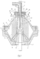
- the part of a centrifugal separator according to the invention shown in figure 1 comprises a rotor, which has a lower part 1 and an upper part 2 which are joined together axially by means of a locking ring 3.
- Inside the centrifugal separator shown as an example there is arranged an axially movable valve slide 4.
- This valve slide 4 delimits together with the upper part 2 a separation chamber 5 and is arranged to open and close an annular gap towards peripheral outlet openings 6 for a substance, which during operation has been separated in the rotor and accumulated at the periphery of the separation chamber 5.
- the valve slide 4 delimits together with the lower part 1 a closing chamber 7, which is provided with an inlet 8 and a throttled outlet 9 for a closing liquid.
- a disc stack 10 is arranged inside the separation chamber 5 consisting of a number of conical separation discs between a distributor 11 and the upper part 2.
- the upper part 2 forms at its in the figure shown upper end an outlet chamber 12, into which in this case a relatively light, separated liquid can flow from the separation chamber 5 via a central passage 13.
- the liquid present in the outlet chamber 12 during operation of the rotor forms a rotating liquid body having a radially inwardly directed free liquid surface 14.
- a stationary inlet tube 15 which opens into an inlet chamber 16 in the interior of the distributor 11.
- a stationary outlet tube 17 is arranged for the specific lighter liquid in the chamber 12.
- An outlet device 18 is arranged in the chamber around the inlet tube 15 and connected to the outlet tube 17.
- the outlet device 18 extends radially outwardly in the outlet chamber 12 and has a portion located outside the radial level of the free liquid surface 14.
- At least one outlet channel 20 is arranged with an inlet opening 19 which is located in this portion of the discharge device.
- the outlet channel 20 is connected to the interior of the inlet tube 17.
- the outlet chamber is axially delimited by two end walls 21 and 22, the end wall 21 delimiting the outlet chamber towards the separation chamber 5.
- the connection 13 is arranged centrally through this end wall 21.
- a device 23 is fixedly attached to this end wall for causing at least a portion of the liquid present in the outlet chamber to rotate at a lower angular speed than the rotor.
- An annular zone 24 of the outlet chamber 12 which surrounds the rotational axis coaxially and in which the inlet opening of the outlet channels is located, is devoid of elements rotating with the rotor and so big that liquid in this zone is able to rotate at a lower angular speed than the rotor.
- passages 26 through which liquid in the outlet chamber flows when the free liquid surface is located radially inside a predetermined radial level 27.
- the passages have inlets, which are located at the predetermined radial level 27, and outlets, which are located radially outside this radial level 27.
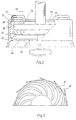
- FIG 2 an outlet chamber 28 in a centrifugal separator according to an embodiment of the invention is shown in more detail.
- the device shown in this figure consist of wall elements 30 fixedly attached to the one end wall 29, the wall elements extending radially, axially, and in circumferential directions, and the wall elements define between themselves channels 31.
- an annular covering device 32 which extends around the rotational axis is fixedly attached and delimits the channels 31 axially from the outlet chamber 28.
- elements 34 are fixedly attached, which form passages having inlets 35 located at the predetermined radial level 36 and having outlets 37 located radially outside this level.
- the circular disc shaped discharge device 38 arranged in the outlet chamber 28 has its radial outer portion positioned at an annular zone 39 of the outlet chamber 28 surrounding the rotational axis, which is free from elements rotating with the rotor and is so big that liquid located in this zone 39 of the outlet chamber 28 is able to rotate at a lower angular speed than the rotor.
- FIG 3 there is shown a view from above of the wall elements 30 and the channels 31 of the device shown in figure 2.
- the channels 31 in the illustrated example converge radially outwardly and are delimited forwardly seen in the rotational direction by a surface, which extends radially between the opening into the outlet chamber 28 of the connection 40 and the free liquid surface and is curved in a plane perpendicular to the rotational axis with a centre of curvature, which for each point on the surface is located behind the surface seen in the rotational direction, and with a radius of curvature, which for essentially each point on the surface is smaller than the radius of curvature of an involute, along which separated liquid strives to move freely radially outwardly relative to the rotor, at the same radius, as the radius at which the point is located.
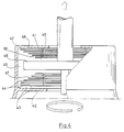
- FIG 4 an outlet chamber 41 in a centrifugal separator according to another embodiment of the invention is shown.
- said device partly consists of wall elements 43 fixedly attached to the end wall 42, which are of the same kind as the wall elements 28 shown in figure 3, and to which a covering device 44 is fixedly attached covering the channels (not shown) between the wall elements 43.
- a covering device 44 is fixedly attached to the axially opposite side of the covering device 44 to the axially opposite side of the covering device 44 , which between themselves form other channels (not shown), which in turn are covered by a further covering device 44.
- a circular disc shaped discharged device 45 is arranged also in this embodiment, which in its radially outer part is surrounded by an annular zone 46 of the outlet chamber 41 surrounding the rotational axis, which is free from elements rotating with the rotor and is so big that liquid located in this zone 46 of the outlet chamber is able to rotate at a lower angular speed than the rotor.
- each disc On each axial side of the discharge device 45 elements rotating with the rotor are arranged in the outer chamber 41, these elements having the form of a number of annular circular discs 47, which delimit passages 48 for the liquid located in the outlet chamber 41.
- each disc Centrally each disc has a circular opening, the centre of which coincides with the rotational axis. The largest radii of the openings are equally big and form inlets 49 to the passages 48 at a predetermined radial level.
- the outlets 50 of the passages 48 are in this shown example located at radii which increase with the distance from the discharge device 45.
- the rotor Upon start of the centrifugal separator the rotor is brought to rotate and the separation chamber 5 is closed by supplying a closing liquid to the closing chamber 7 through the inlet 8.
- the liquid which is to be centrifugally treated, can be supplied to the separation chamber through the inlet tube 15 and the inlet chamber 16.
- the separation chamber 5 reaches its operational speed and the conditions are stabilized inside the separation chamber. The components in the supplied liquid are separated under the influence of the centrifugal forces acting on them.
- the separation takes place mainly in the spaces between the conical discs in the disc stack 10. During the separation the specific heavier component is thrown radially outwardly and is collected at the radially outermost part of the separation chamber, whereas a specific lighter liquid flows radially inwardly in these spaces.
- the specific heavier component is discharged intermittently during operation by moving the valve slide 4 to uncover the peripheral outlet openings 6 for certain time periods.
- the specific lighter liquid flows out of the separation chamber 5 through connection passages 13 to the outlet chamber 12, in which it forms a rotating liquid body with a radially inwardly directed free liquid surface.
- the liquid present in the outlet chamber 12 is discharged through the outlet 19 and further out through the outlet channel 20 in the stationary outlet device 18.
- This surface is curved in a plane perpendicular to the rotational axis with a centre of curvature, which for essentially each point on this portion of the surface is located behind the surface seen in the rotational direction, and with a radius of curvature, which for each point on this portion of the surface is smaller than the radius of curvature of an involute, along which separated liquid strives to move freely radially outwardly relative to the rotor, at the same radius as the radius at which the point is located.
- liquid present in the outlet chamber can by different design of channels in the separation chamber be given a lower angular speed already before it enters the outlet chamber.
- the liquid flow into the outlet chamber can be directed in a way such that its angular speed becomes lower than the rotor.
- Another alternative is to recirculate a portion of the liquid, which has been discharged by the stationary discharge device, to the outlet chamber.
Landscapes
- Centrifugal Separators (AREA)
Claims (9)
- Procédé pour régler, pendant le fonctionnement, le débit de sortie d'un liquide séparé dans une chambre de séparation (5) dans un rotor d'un séparateur centrifuge, le rotor pouvant tourner autour d'un axe de rotation dans un sens de rotation prédéterminé procédé selon lequel le liquide séparé est envoyé dans une chambre de sortie (12,28,41) de manière à former dans cette chambre un corps de liquide rotatif possédant une surface libre (14) dirigée radialement vers l'intérieur, et est évacué de la chambre de sortie (12,28,41) par l'intermédiaire d'un dispositif d'évacuation stationnaire (18,38,45) possédant au moins un canal interne de sortie (20) pourvu d'une ouverture d'entrée (19) dans une partie radiale extérieure du dispositif de sortie (18,38,45) qui, pendant le fonctionnement, est situé radialement à l'extérieur de la surface libre (14) du liquide,
caractérisé en ce
que le liquide séparé est évacué par le conduit de sortie (20) avec un débit de sortie réglé par le faitqu'on amène au moins une partie du liquide séparé présent dans la chambre de sortie (12,28,41) à tourner avec une vitesse angulaire inférieure à celle du rotor dans une zone annulaire (24,39,46) de la chambre de sortie qui entoure coaxialement l'axe de rotation et est dénuée d'éléments tournant avec le rotor, zone dans laquelle est située l'ouverture d'entrée (19), etqu'on amène le liquide présent dans ladite zone (24,39, 46) à circuler dans au moins un passage (26,48) délimité par des éléments (25,34,47) tournant avec le rotor et possédant une entrée (35,49) et une sortie (37,50) située radialement à l'extérieur de cette entrée (35,49) dans la chambre de sortie (12,28,41), lorsque la surface de liquide libre est à un niveau situé radialement endeçà d'un niveau radial prédéterminé (27,36), auquel l'entrée (35,49) du passage se situe. - Procédé selon la revendication 1, caractérisé en ce que le liquide séparé est introduit dans la chambre de sortie (12,28,41) radialement à l'intérieur de la surface libre (14) du liquide et en ce que le liquide pénétrant dans la chambre de sortie (12,28,41) est amené à circuler radialement vers l'extérieur en direction de la surface libre (14) du liquide en traversant des canaux (31) le long de et en contact avec une surface d'un élément de paroi (30,43), la surface délimitant le conduit vers l'avant, lorsqu'on regarde dans le sens de rotation, et s'étendant radialement, axialement et dans la direction circonférentielle et étant courbe dans un plan perpendiculaire à l'axe de rotation, avec un centre de courbure qui, en chaque point de la surface, est situé en arrière de la surface vue dans le sens de rotation, et possède un rayon de courbure qui, essentiellement en chaque point de la surface, est inférieur au rayon de courbure d'une courbe en développante, le long de laquelle le liquide séparé tend librement à se déplacer radialement vers l'extérieur par rapport au rotor sur le rayon, sur lequel ledit point est situé.
- Séparateur centrifuge pour la mise en oeuvre du procédé selon la revendication 1, comprenant un rotor, qui peut tourner autour d'un axe de rotation dans un sens prédéterminé et forme :le séparateur centrifuge comprenant également un dispositif stationnaire (18,38,45) disposé dans la chambre de sortie (12,28,41) possédant au moins un conduit de sortie (20) raccordé à une sortie (17) et possédant une ouverture d'entrée (19) dans une partie du dispositif d'évacuation (18,38,45), qui est située radialement à l'extérieur de la surface libre (14) du liquide,une chambre d'entrée (16) pour un liquide devant être traité par centrifugation,une chambre de séparation (5) raccordée à la chambre d'entrée (16),une chambre de sortie (12,28,41) délimitée axialement par deux parois d'extrémité (21,22,33,42) et radialement par une paroi circonférentielle raccordant des parois d'extrémité, une chambre de sortie étant agencée de telle sorte que, pendant le fonctionnement, un liquide séparé dans la chambre de séparation (15) pénètre dans la chambre de sortie (12,28,41) et forme dans cette chambre un corps de liquide rotatif possédant une surface libre (14) du liquide, dirigée radialement vers l'intérieur, etun raccord (13,40) raccordant la chambre de sortie (12, 28,41) à la chambre de séparation (5), le raccord (13, 40) étant disposé de manière à traverser l'une desdites parois d'extrémité (21,29,42) et possédant une ouverture dans la chambre de sortie (12,28,41) située radialement à l'intérieur du niveau radial de la surface libre du liquide,
caractérisé en ceque l'ouverture d'entrée (19) est située dans une zone annulaire (24,39,46) de la chambre de sortie (12,28,41), qui entoure l'axe de rotation et qui ne comporte aucun élément tournant avec le rotor et est suffisamment grande pour que le liquide puisse tourner dans cette zone à une vitesse angulaire nettement inférieure à celle du rotor,qu'un dispositif (23,30,43) est disposé en étant raccordé à la chambre de sortie (12,28,41) pour amener au moins une partie du liquide présente dans ladite zone (24,39,46) de la chambre de sortie (12,28,41) à une vitesse angulaire inférieure à celle du rotor, etque des éléments (25,34,47), qui tournent avec le rotor, forment au moins un passage (26,48) possédant une entrée (35,49) située dans la chambre de sortie (12,28,41) à un niveau radial prédéterminé (27,36) radialement à l'intérieur de l'ouverture d'entrée (19) du canal de sortie (20), et une sortie (37,50) située radialement à l'extérieur de son niveau radial pour que le liquide séparé circule radialement vers l'extérieur en traversant ce passage (26,48) lorsque ladite surface du liquide est située radialement à l'intérieur de l'entrée (35,49) du passage. - Séparateur centrifuge selon la revendication 3, caractérisé en ce que ledit dispositif comprend au moins deux éléments de paroi (30,43) disposés dans la chambre de sortie (12,28,41) et raccordés de façon fixe à ladite paroi d'extrémité (21,29,42) , lesdits éléments de paroi (30,40) s'étendant radialement, axialement et dans la direction circonférentielle et formant entre eux un conduit (31) pour conduire un liquide séparé pénétrant dans la chambre de sortie (12,28,41) par l'intermédiaire dudit raccord (13,40) radialement vers l'extérieur en direction de la surface libre (14) du liquide, le conduit étant délimité vers l'avant, lorsqu'on regarde dans le sens de rotation, par une surface d'un élément de paroi (30,43), au moins une partie de la surface s'étendant radialement entre l'ouverture du raccord débouchant dans la chambre de sortie (12,28,41) et la surface libre (14) du liquide incurvé dans un plan perpendiculaire à l'axe de rotation, avec un centre de courbure qui, essentiellement en chaque point de cette partie de la surface, est situé en arrière de la surface lorsqu'on regarde dans le sens de rotation, et avec un rayon de courbure qui, en chaque point de cette partie de la surface, est inférieur à un rayon de courbure d'une courbe en développante, le long de laquelle le liquide séparé tend à se déplacer librement radialement vers l'extérieur par rapport au rotor, sur le même rayon que le rayon sur lequel le point est situé.
- Séparateur centrifuge selon la revendication 4, caractérisé en ce qu'un dispositif de recouvrement (32, 44) est raccordé de façon fixe aux éléments de paroi (30, 43) sur leurs côtés axiaux éloignés de ladite paroi d'extrémité (29,42), le dispositif de recouvrement isolant, par rapport à la chambre de sortie (12,28,41), au moins une partie du conduit (31) qui est le plus proche du raccord.
- Séparateur centrifuge selon la revendication 3, 4 ou 5, caractérisé en ce que lesdits éléments (34,47) forment au moins deux passages, dont chacun comporte une entrée (35,49) située au niveau radial prédéterminé.
- Séparateur centrifuge selon la revendication 6, caractérisé en ce que les sorties (50) des passages sont situées à différents niveaux radiaux.
- Séparateur centrifuge selon l'une quelconque des revendications 3-7, caractérisé en ce que lesdits éléments comprennent au moins un disque annulaire (47), qui s'étend autour de l'axe de rotation et s'étend radialement vers l'extérieur en direction du niveau radial prédéterminé.
- Séparateur centrifuge selon la revendication 8, caractérisé en ce que le disque annulaire possède une ouverture circulaire concentrique à l'axe de rotation.
Applications Claiming Priority (3)
| Application Number | Priority Date | Filing Date | Title |
|---|---|---|---|
| SE9301743 | 1993-05-21 | ||
| SE9301743A SE501197C2 (sv) | 1993-05-21 | 1993-05-21 | Sätt att i en centrifugalseparator reglera utflödet av en separerad vätska och en centrifugalseparator för utförande av sättet |
| PCT/SE1994/000466 WO1994027726A1 (fr) | 1993-05-21 | 1994-05-19 | Procede pour reguler le debit de sortie d'un liquide separe dans un separateur centrifuge et separateur centrifuge de mise en ×uvre du procede |
Publications (2)
| Publication Number | Publication Date |
|---|---|
| EP0699107A1 EP0699107A1 (fr) | 1996-03-06 |
| EP0699107B1 true EP0699107B1 (fr) | 1999-07-21 |
Family
ID=20390013
Family Applications (1)
| Application Number | Title | Priority Date | Filing Date |
|---|---|---|---|
| EP94916468A Expired - Lifetime EP0699107B1 (fr) | 1993-05-21 | 1994-05-19 | Procede pour reguler le debit de sortie d'un liquide separe dans un separateur centrifuge et separateur centrifuge de mise en oeuvre du procede |
Country Status (6)
| Country | Link |
|---|---|
| US (1) | US5599271A (fr) |
| EP (1) | EP0699107B1 (fr) |
| JP (1) | JPH08510161A (fr) |
| DE (1) | DE69419604T2 (fr) |
| SE (1) | SE501197C2 (fr) |
| WO (1) | WO1994027726A1 (fr) |
Families Citing this family (11)
| Publication number | Priority date | Publication date | Assignee | Title |
|---|---|---|---|---|
| SE501199C2 (sv) * | 1993-05-21 | 1994-12-05 | Alfa Laval Separation Ab | Centrifugalseparator |
| US6706180B2 (en) | 2001-08-13 | 2004-03-16 | Phase Inc. | System for vibration in a centrifuge |
| DE10143405C2 (de) * | 2001-09-05 | 2003-12-18 | Westfalia Separator Ag | Schälscheibenvorrichtung zum Ableiten von Flüssigkeit aus einer Zentrifugentrommel |
| US7320750B2 (en) * | 2003-03-11 | 2008-01-22 | Phase Inc. | Centrifuge with controlled discharge of dense material |
| US6971525B2 (en) * | 2003-06-25 | 2005-12-06 | Phase Inc. | Centrifuge with combinations of multiple features |
| WO2005011848A1 (fr) * | 2003-07-30 | 2005-02-10 | Phase Inc. | Systeme de filtration et procede de separation de fluide dynamique |
| WO2005011833A2 (fr) * | 2003-07-30 | 2005-02-10 | Phase Inc. | Systeme de filtration a nettoyage ameliore et separation de fluide dynamique |
| US7282147B2 (en) * | 2003-10-07 | 2007-10-16 | Phase Inc. | Cleaning hollow core membrane fibers using vibration |
| DK200801848A (en) | 2008-12-30 | 2010-07-01 | Alfa Laval Corp Ab | A decanter centrifuge and a decanter centrifuge discharge port memeber. |
| DK200801846A (en) | 2008-12-30 | 2010-07-01 | Alfa Laval Corp Ab | A decanter centrifuge with a slide valve body |
| DE102013015019A1 (de) | 2013-09-10 | 2015-03-12 | Bogdan Vuletic | Verfahren und Anlage zur Vergasung von Kohlenstoffträgern und Weiterverarbeitung des produzierten Gases |
Family Cites Families (7)
| Publication number | Priority date | Publication date | Assignee | Title |
|---|---|---|---|---|
| SE180619C1 (fr) * | ||||
| CA710185A (en) * | 1965-05-25 | V. S. Lundahl Lennart | Homogenizing method and apparatus | |
| CH156097A (fr) * | 1930-12-30 | 1932-07-31 | Leonard Ringius Carlos | Dispositif pour machines purifieuses et écrémeuses de lait. |
| DE630308C (de) * | 1934-06-30 | 1936-05-25 | Bergedorfer Eisenwerk Ag | Verfahren und Vorrichtung zum Abfuehren der Schleuderfluessigkeit aus einer Schleudertrommel |
| DE3604312A1 (de) * | 1986-02-12 | 1987-08-13 | Westfalia Separator Ag | Trennzentrifuge mit vertikaler drehachse und einer schaeleinrichtung |
| SE502308C2 (sv) * | 1986-04-19 | 1995-10-02 | Westfalia Separator Ag | Kontinuerligt arbetande centrifugtrumma för koncentrering av suspenderade fasta partiklar |
| SE459159B (sv) * | 1987-10-08 | 1989-06-12 | Alfa Laval Separation Ab | Centrifugalseparator med utmatningsorgan |
-
1993
- 1993-05-21 SE SE9301743A patent/SE501197C2/sv unknown
-
1994
- 1994-05-19 US US08/553,402 patent/US5599271A/en not_active Expired - Fee Related
- 1994-05-19 DE DE69419604T patent/DE69419604T2/de not_active Expired - Fee Related
- 1994-05-19 JP JP6524707A patent/JPH08510161A/ja active Pending
- 1994-05-19 WO PCT/SE1994/000466 patent/WO1994027726A1/fr not_active Ceased
- 1994-05-19 EP EP94916468A patent/EP0699107B1/fr not_active Expired - Lifetime
Also Published As
| Publication number | Publication date |
|---|---|
| DE69419604T2 (de) | 1999-11-11 |
| DE69419604D1 (de) | 1999-08-26 |
| SE9301743D0 (sv) | 1993-05-21 |
| SE9301743L (sv) | 1994-11-22 |
| JPH08510161A (ja) | 1996-10-29 |
| SE501197C2 (sv) | 1994-12-05 |
| EP0699107A1 (fr) | 1996-03-06 |
| WO1994027726A1 (fr) | 1994-12-08 |
| US5599271A (en) | 1997-02-04 |
Similar Documents
| Publication | Publication Date | Title |
|---|---|---|
| EP0809536B1 (fr) | Dispositif d'entree pour un separateur centrifuge | |
| US5779619A (en) | Centrifugal separator | |
| EP0390899B1 (fr) | Separateur centrifuge | |
| US5052996A (en) | Centrifugal separator | |
| EP0612270B1 (fr) | Separateur centrifuge | |
| US5599271A (en) | Method of regulating the outlet flow of a liquid separated in a centrifugal separator and a centrifugal separator to carry out the method | |
| KR20020008208A (ko) | 원심 분리기의 계면의 반경 방향 레벨 조절 방법 | |
| KR970004702B1 (ko) | 원심 분리기 | |
| JPH11511059A (ja) | 遠心分離機 | |
| US5518494A (en) | Centrifugal separator with air entrainment suppression | |
| EP1075331B1 (fr) | Procede et appareil de nettoyage d'un separateur centrifuge | |
| EP0370068B1 (fr) | Separateur centrifuge avec dispositif de decharge | |
| WO1993025314A1 (fr) | Separateur centrifuge | |
| KR0155957B1 (ko) | 에너지 변환장치를 가진 원심 분리기 | |
| EP0703829B1 (fr) | Separateur centrifuge | |
| EP0616557B1 (fr) | Separateur centrifuge | |
| AU561193B2 (en) | Outlet arrangement for a centrifugal separator | |
| WO1988002664A1 (fr) | Separateur centrifuge pourvu d'un organe d'evacuation fixe |
Legal Events
| Date | Code | Title | Description |
|---|---|---|---|
| PUAI | Public reference made under article 153(3) epc to a published international application that has entered the european phase |
Free format text: ORIGINAL CODE: 0009012 |
|
| 17P | Request for examination filed |
Effective date: 19951121 |
|
| AK | Designated contracting states |
Kind code of ref document: A1 Designated state(s): DE FR IT |
|
| 17Q | First examination report despatched |
Effective date: 19980223 |
|
| GRAG | Despatch of communication of intention to grant |
Free format text: ORIGINAL CODE: EPIDOS AGRA |
|
| GRAG | Despatch of communication of intention to grant |
Free format text: ORIGINAL CODE: EPIDOS AGRA |
|
| GRAG | Despatch of communication of intention to grant |
Free format text: ORIGINAL CODE: EPIDOS AGRA |
|
| GRAH | Despatch of communication of intention to grant a patent |
Free format text: ORIGINAL CODE: EPIDOS IGRA |
|
| GRAH | Despatch of communication of intention to grant a patent |
Free format text: ORIGINAL CODE: EPIDOS IGRA |
|
| GRAA | (expected) grant |
Free format text: ORIGINAL CODE: 0009210 |
|
| AK | Designated contracting states |
Kind code of ref document: B1 Designated state(s): DE FR IT |
|
| REF | Corresponds to: |
Ref document number: 69419604 Country of ref document: DE Date of ref document: 19990826 |
|
| ET | Fr: translation filed | ||
| PGFP | Annual fee paid to national office [announced via postgrant information from national office to epo] |
Ref country code: FR Payment date: 20000510 Year of fee payment: 7 |
|
| PGFP | Annual fee paid to national office [announced via postgrant information from national office to epo] |
Ref country code: DE Payment date: 20000515 Year of fee payment: 7 |
|
| PLBE | No opposition filed within time limit |
Free format text: ORIGINAL CODE: 0009261 |
|
| STAA | Information on the status of an ep patent application or granted ep patent |
Free format text: STATUS: NO OPPOSITION FILED WITHIN TIME LIMIT |
|
| 26N | No opposition filed | ||
| PG25 | Lapsed in a contracting state [announced via postgrant information from national office to epo] |
Ref country code: FR Free format text: LAPSE BECAUSE OF NON-PAYMENT OF DUE FEES Effective date: 20020131 |
|
| PG25 | Lapsed in a contracting state [announced via postgrant information from national office to epo] |
Ref country code: DE Free format text: LAPSE BECAUSE OF NON-PAYMENT OF DUE FEES Effective date: 20020301 |
|
| PG25 | Lapsed in a contracting state [announced via postgrant information from national office to epo] |
Ref country code: IT Free format text: LAPSE BECAUSE OF NON-PAYMENT OF DUE FEES;WARNING: LAPSES OF ITALIAN PATENTS WITH EFFECTIVE DATE BEFORE 2007 MAY HAVE OCCURRED AT ANY TIME BEFORE 2007. THE CORRECT EFFECTIVE DATE MAY BE DIFFERENT FROM THE ONE RECORDED. Effective date: 20050519 |