EP0699155B1 - Segelbaumstruktur - Google Patents
Segelbaumstruktur Download PDFInfo
- Publication number
- EP0699155B1 EP0699155B1 EP95912512A EP95912512A EP0699155B1 EP 0699155 B1 EP0699155 B1 EP 0699155B1 EP 95912512 A EP95912512 A EP 95912512A EP 95912512 A EP95912512 A EP 95912512A EP 0699155 B1 EP0699155 B1 EP 0699155B1
- Authority
- EP
- European Patent Office
- Prior art keywords
- boom
- carriage
- sail
- edges
- slotted hole
- Prior art date
- Legal status (The legal status is an assumption and is not a legal conclusion. Google has not performed a legal analysis and makes no representation as to the accuracy of the status listed.)
- Expired - Lifetime
Links
- 230000008878 coupling Effects 0.000 claims description 10
- 238000010168 coupling process Methods 0.000 claims description 10
- 238000005859 coupling reaction Methods 0.000 claims description 10
- 239000004411 aluminium Substances 0.000 claims description 8
- 229910052782 aluminium Inorganic materials 0.000 claims description 8
- XAGFODPZIPBFFR-UHFFFAOYSA-N aluminium Chemical compound [Al] XAGFODPZIPBFFR-UHFFFAOYSA-N 0.000 claims description 8
- 238000004804 winding Methods 0.000 claims description 8
- 238000006073 displacement reaction Methods 0.000 claims description 5
- 238000001125 extrusion Methods 0.000 claims description 4
- 241000545744 Hirudinea Species 0.000 claims description 3
- 230000000903 blocking effect Effects 0.000 claims description 3
- RTAQQCXQSZGOHL-UHFFFAOYSA-N Titanium Chemical compound [Ti] RTAQQCXQSZGOHL-UHFFFAOYSA-N 0.000 claims description 2
- 229910052751 metal Inorganic materials 0.000 claims description 2
- 239000002184 metal Substances 0.000 claims description 2
- 229910001220 stainless steel Inorganic materials 0.000 claims description 2
- 239000010935 stainless steel Substances 0.000 claims description 2
- 239000010936 titanium Substances 0.000 claims description 2
- 229910052719 titanium Inorganic materials 0.000 claims description 2
- OKTJSMMVPCPJKN-UHFFFAOYSA-N Carbon Chemical compound [C] OKTJSMMVPCPJKN-UHFFFAOYSA-N 0.000 description 2
- 229910052799 carbon Inorganic materials 0.000 description 2
- 239000000463 material Substances 0.000 description 2
- 239000004033 plastic Substances 0.000 description 2
- 229920003023 plastic Polymers 0.000 description 2
- 241000531908 Aramides Species 0.000 description 1
- 239000004593 Epoxy Substances 0.000 description 1
- 229920002430 Fibre-reinforced plastic Polymers 0.000 description 1
- 238000004026 adhesive bonding Methods 0.000 description 1
- 229920003235 aromatic polyamide Polymers 0.000 description 1
- 238000005452 bending Methods 0.000 description 1
- 230000008901 benefit Effects 0.000 description 1
- 230000008859 change Effects 0.000 description 1
- 239000004035 construction material Substances 0.000 description 1
- 230000000881 depressing effect Effects 0.000 description 1
- 239000011151 fibre-reinforced plastic Substances 0.000 description 1
- 239000003365 glass fiber Substances 0.000 description 1
- 239000003292 glue Substances 0.000 description 1
- 230000007246 mechanism Effects 0.000 description 1
- 239000000203 mixture Substances 0.000 description 1
- 229920002635 polyurethane Polymers 0.000 description 1
- 239000004814 polyurethane Substances 0.000 description 1
- 230000003014 reinforcing effect Effects 0.000 description 1
Images


Classifications
-
- B—PERFORMING OPERATIONS; TRANSPORTING
- B63—SHIPS OR OTHER WATERBORNE VESSELS; RELATED EQUIPMENT
- B63H—MARINE PROPULSION OR STEERING
- B63H9/00—Marine propulsion provided directly by wind power
- B63H9/04—Marine propulsion provided directly by wind power using sails or like wind-catching surfaces
- B63H9/08—Connections of sails to masts, spars, or the like
- B63H9/10—Running rigging, e.g. reefing equipment
- B63H9/1021—Reefing
- B63H9/1042—Reefing by furling around or inside the boom
Definitions
- the invention relates to a boom for a sailing boat comprising:
- Such a boom-structure is known from EP-A-0 229 675.
- the boom of the type stated in the preamble has the feature that the slotted hole is bounded by two mutually parallel prismatic edges with which a carriage movable therealong co-acts such that the carriage prevents a relative displacement of these edges away from each other, which carriage is movable at least partly by second drive means.
- the characterizing feature according to which the second drive means comprise at least one cable which is connected to the carriage and on which a tensile force can be exerted by a motor, has the technical advantage that a tensile force directed away from the mast can be of particular importance for tensioning and holding tensioned the foot.
- the boom according to the invention has the feature that the carriage is slidable.
- the carriage can also be rollable.
- the carriage can engage round the said edges or the edges can engage round the carriage.
- the carriage has a number of functions.
- a first function is to tension and hold tensioned the foot when the sail is reefed out.
- the carriage can effectively hold together the said edges in diverse reefing positions, while in reefed and non-reefed situation the carriage can be used for stretching the foot.
- the swing tension in the reefed situation can be fixed at a predetermined value.
- a particular embodiment has the special feature that the first drive means comprise at least one element which extends in lengthwise direction, is rotatably drivable round its longitudinal axis and which is coupled to the sail for exerting on that sail during operation of the drive means a tensile force for displacing the sail through the slotted hole to the cavity.
- the drive means must be able to exert a sufficiently large tensile force on the sail to overcome the opposing force or forces exerted by this sail, particularly when there is some wind load.
- a specific embodiment has the feature that the element is a winding shaft extending in longitudinal direction in the cavity.
- the boom according to the invention preferably has the special feature that in any operating position of the sail the carriage assumes relative to the boom a position which in any reefed situation is located closer to the mast than in non-reefed situation.
- the boom is provided with a carriage which can be fixed relative to the boom by blocking means.
- the carriage can be provided for this purpose with manually operated blocking means, while in the above described embodiment the fixing can consist of the fact that the motor is of the self-braking type.
- the boom can be manufactured of any suitable construction material or composition thereof, for instance aluminium.
- the boom In the case where the boom has a prismatic shape, that is, a shape in which the cross section is identical everywhere along the whole length, the boom can be embodied as extrusion profile.
- the boom can also be embodied in a fibre-reinforced plastic, a sandwich structure or other structure of sufficient strength. Particularly fibres with tensile strength such as carbon fibres, glass fibres, aramide and the like are very suitable for reinforcing purposes.
- the boom-structure consists substantially of plastic
- the boom can advantageously have the feature that at least the edges of the slotted hole are manufactured by extrusion.
- This embodiment can display the special feature that the edges consist of aluminium.
- the boom-structure consists for the major part of plastic, for instance a sandwich structure of an epoxy material with carbon fibres as skin plates, together with a polyurethane filling, the said edges of for instance extruded aluminium can be coupled thereto by bolts and a glue connection.
- the carriage can in principle be manufactured of any suitable material.
- the preferred embodiment has the special feature that the carriage consists of metal, for example stainless steel, aluminium, titanium.
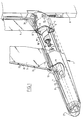
- FIG. 1 shows a boom 1 according to the invention in a first embodiment.
- Boom 1 comprises an elongate structure 2 of aluminium which bounds a cavity 3 extending in lengthwise direction, a slotted hole 4 extending on the top side of the structure 2 thereof in lengthwise direction and a winding shaft 6 drivable by a motor 5 and extending in lengthwise direction for winding up and unwinding a sail movable through the slotted hole 4.
- the motor 5 serves particularly to exert a downward directed tensile force on a sail 7 which is connected guidably in vertical direction to a mast 8.
- the winding shaft 6 serves particularly to pull through the slotted hole 4 into the cavity 3 and store therein a part 9 of the sail 7 for placing out of use.
- the winding shaft 6 is preferably embodied more or less with torsional stiffness. Sail 7 is inserted into shaft 6 via an undercut longitudinal channel 10 by means of a widened bottom edge into which for instance a cable is woven.
- the slotted hole 4 is bounded by two mutually parallel prismatic edges 11, 12 in which a carriage 13 is received slidably for movement therealong.
- the edges 11, 12 have a curved form with mutually facing openings, while carriage 13, as can be seen particularly in figure 2, has widened side parts 14, 15 having a partially cylindrical form which fit into the cavities in edges 11, 12, which parts 14, 15 are coupled to the rest of the carriage 13 via narrowed bridges 16, 17 respectively which are narrow enough to pass through the longitudinal openings in edges 11, 12, while the side parts 14, 15 are too wide to do so.
- the carriage 13 is thus slidably accommodated between the edges, while it blocks a relative displacement of these edges 11, 12 away from each other.
- the carriage 3 is coupled via the side parts 14, 15 to mutually parallel cables 18, 19 which are displaceable by means of a schematically designated motor 20 with co-movement of the carriage 13.
- motor 20 with co-movement of the carriage 13.
- the carriage 13 comprises two hooks 21, 22 which extend on either side and which are open on the underside and are thus accessible by the correspondingly formed blocks 23, 24 shown in figure 3 which are connected to the upward inclining, strengthened free edge 25 of sail 7, and are arranged at a number of positions thereon as shown in figure 1, and which block the upward directed movement 26 of the sail 7 under load.
- the motor 5 In order to wind up the sail 7 the motor 5, preferably a hydraulic motor, is energized. A downward directed force 7 is hereby exerted on the sail, whereby the connection between the blocks 23, 24 and the hooks 21, 22 is broken. After reaching a desired position the connection between following sets of blocks 23, 24 on the one hand and hooks 21, 22 on the other can be restored after a displacement of carriage 13 is performed via cables 18, 19 by energizing the hydraulic motor 20 such that the carriage is placed at the correct position.
- Figure 4 shows a variant in which the carriage 28 is manually slidable along the edges 11, 12. By means of a spring-loaded braking mechanism the carriage 28 retains a chosen position relative to the boom 1. By depressing a control lever 29 the rigid coupling between carriage 28 and boom 1 is released and carriage 28 can slide.
- the structure according to figure 4 is otherwise the same as that according to figure 1.
- Figure 5 shows the manner in which the boom 1 is coupled to the mast 8.
- the latter supports via a hinge 30 a guide rail 31 curved in a circular arc with which co-acts a correspondingly formed slide channel 32 with the undercut form shown in figure 5.
- the slide channel 32 is thus rotatable, wherein the luff 26 extends in the middle zone of the rotation.
- the channel 32 forms part of a support disc 33 to which the boom 1 is connected.
- the front edge of the sail 7, that is, the zone adjoining the luff 26, also comprises blocks 34, 35 which are arranged at mutual distances and correspond with the blocks 23, 24 and which can co-act with correspondingly formed hooks 36, 37 in a hooking body 38 which is coupled to the support disc 33 for tensile strength and for sliding by means of undercut longitudinal recesses 39, 30.
- Figure 6 shows a rear view of a boom 41 in another embodiment.
- the boom 41 is provided with coupling edges 42, 43 of aluminium, which coupling edges 42, 43 are manufactured by extrusion.
- the edges 42, 43 are connected to the rest of the boom 41 by glueing and making use of bolts 44.
Landscapes
- Engineering & Computer Science (AREA)
- Life Sciences & Earth Sciences (AREA)
- Sustainable Development (AREA)
- Sustainable Energy (AREA)
- Chemical & Material Sciences (AREA)
- Combustion & Propulsion (AREA)
- Mechanical Engineering (AREA)
- Ocean & Marine Engineering (AREA)
- Jib Cranes (AREA)
- Toys (AREA)
Claims (11)
- Baum für ein Segelboot mit:einer länglichen Struktur, die einen sich in Längsrichtung erstreckenden Hohlraum begrenzt;einem Langloch, das sich an deren Oberseite in Längsrichtung erstreckt; undeinem Zugelement, das mittels erster Antriebsmittel antreibbar ist und sich in Längsrichtung erstreckt, um einen Teil des Segels, der unwirksam werden bzw. sein soll, durch das Langloch in den Hohlraum zu ziehen und darin zu lagern,
wobei das Langloch von zwei zueinander parallelen, prismaförmigen Kanten begrenzt ist, mit denen ein daran entlang beweglicher Schlitten derart zusammenwirkt, daß der Schlitten eine relative Verlagerung dieser Kanten voneinander weg verhindert und der Schlitten wenigstens teilweise mit Hilfe der zweiten Antriebsmittel bewegbar ist,
dadurch gekennzeichnet, daßdie zweiten Antriebsmittel wenigstens ein Kabel aufweisen, das mit dem Schlitten verbunden ist und auf das eine Zugkraft mit Hilfe eines Motors ausgeübt werden kann;der Schlitten und das Segel im Bereich ihres Lieks mittels Kopplungsmitteln gekoppelt werden können; unddie Kopplungsmittel Einhakmittel aufweisen. - Baum nach Anspruch 1, dadurch gekennzeichnet, daß der Schlitten verschiebbar ist.
- Baum nach Anspruch 1, dadurch gekennzeichnet, daß der Schlitten rollbar ist.
- Baum nach Anspruch 1, dadurch gekennzeichnet, daß die ersten Antriebsmittel wenigstens ein Element aufweisen, das sich in Längsrichtung erstreckt, drehend um seine Längsachse antreibbar und mit dem Segel gekoppelt ist, um auf das Segel während des Betriebs der Antriebsmittel eine Zugkraft auszuüben, um das Segel durch das Langloch zum Hohlraum zu verlagern.
- Baum nach Anspruch 4, dadurch gekennzeichnet, daß das Element ein Wickelschaft ist, der sich in Längsrichtung in dem Hohlraum erstreckt.
- Baum nach Anspruch 1, dadurch gekennzeichnet, daß der Schlitten in jeder Betriebsstellung des Segels relativ zu dem Baum eine Stellung einnimmt, die in jeder Reffsituation näher dem Mast ist als in der nicht gerefften Situation.
- Baum nach Anspruch 1, dadurch gekennzeichnet, daß der Schlitten mit Hilfe von Blockiermitteln relativ zu dem Baum fixiert werden kann.
- Baum nach Anspruch 7, dadurch gekennzeichnet, daß der Motor vom selbstbremsenden Typ ist.
- Baum nach Anspruch 1, dadurch gekennzeichnet, daß wenigstens die Kanten des Langlochs mittels Extrusion hergestellt sind.
- Baum nach Anspruch 9, dadurch gekennzeichnet, daß die Kanten aus Aluminium bestehen.
- Baum nach Anspruch 1, dadurch gekennzeichnet, daß der Schlitten aus Metall, beispielsweise rostfreiem Stahl, Aluminium, Titan, besteht.
Applications Claiming Priority (3)
| Application Number | Priority Date | Filing Date | Title |
|---|---|---|---|
| NL9400485 | 1994-03-25 | ||
| NL9400485 | 1994-03-25 | ||
| PCT/NL1995/000115 WO1995026296A1 (en) | 1994-03-25 | 1995-03-24 | Boom-structure |
Publications (2)
| Publication Number | Publication Date |
|---|---|
| EP0699155A1 EP0699155A1 (de) | 1996-03-06 |
| EP0699155B1 true EP0699155B1 (de) | 1998-10-14 |
Family
ID=19863998
Family Applications (1)
| Application Number | Title | Priority Date | Filing Date |
|---|---|---|---|
| EP95912512A Expired - Lifetime EP0699155B1 (de) | 1994-03-25 | 1995-03-24 | Segelbaumstruktur |
Country Status (7)
| Country | Link |
|---|---|
| US (1) | US5640919A (de) |
| EP (1) | EP0699155B1 (de) |
| AU (1) | AU1963395A (de) |
| CA (1) | CA2163241A1 (de) |
| DE (1) | DE69505322T2 (de) |
| ES (1) | ES2122567T3 (de) |
| WO (1) | WO1995026296A1 (de) |
Families Citing this family (10)
| Publication number | Priority date | Publication date | Assignee | Title |
|---|---|---|---|---|
| AUPO275096A0 (en) * | 1996-07-25 | 1996-10-31 | Brookes, Thomas Joseph | Furling boom |
| AU727805B2 (en) * | 1996-07-25 | 2000-12-21 | Thomas Joseph Brookes | Furling boom |
| US6431100B2 (en) * | 2000-03-24 | 2002-08-13 | Charles Allen Abshier | Stowable semi-rigid wing sail system |
| US6371037B1 (en) | 2000-12-26 | 2002-04-16 | Fred C. Cook | Sail furling system |
| CA2579446A1 (en) * | 2003-09-09 | 2005-03-17 | Roberts, Patricia | Masted vehicle |
| AT504907B1 (de) * | 2007-07-10 | 2008-09-15 | Waldhauser Kurt | Rollreffbaum für segelschiffe |
| US7918175B2 (en) * | 2007-09-20 | 2011-04-05 | Steven Daniel Orlebeke | Mast track extension and pre-feeder for mainsail furling |
| AT506349B1 (de) * | 2008-02-06 | 2009-11-15 | Waldhauser Kurt | Profilsegelbaum für segelschiffe |
| FR3016340A1 (fr) * | 2014-01-14 | 2015-07-17 | Paul-Henri Decamp | Aile de propulsion pour navire a voilure enroulable verticalement |
| CN107399680A (zh) * | 2017-09-21 | 2017-11-28 | 浙江海洋大学 | 一种船舶用吊机 |
Family Cites Families (4)
| Publication number | Priority date | Publication date | Assignee | Title |
|---|---|---|---|---|
| SE397072B (sv) * | 1976-02-19 | 1977-10-17 | Larsson K O A H | Anordning vid rigg for segelfartyg |
| US4679520A (en) * | 1985-06-10 | 1987-07-14 | Harken Olaf T | Mainsail reefing and furling device and method |
| DK167181B1 (da) * | 1986-01-17 | 1993-09-13 | Mogens Pedersen | Rullebom til en sejlbaad |
| US5181477A (en) * | 1990-09-05 | 1993-01-26 | Harken, Inc. | Boom for sailing vessel |
-
1995
- 1995-03-24 EP EP95912512A patent/EP0699155B1/de not_active Expired - Lifetime
- 1995-03-24 DE DE69505322T patent/DE69505322T2/de not_active Expired - Fee Related
- 1995-03-24 US US08/549,748 patent/US5640919A/en not_active Expired - Lifetime
- 1995-03-24 AU AU19633/95A patent/AU1963395A/en not_active Abandoned
- 1995-03-24 ES ES95912512T patent/ES2122567T3/es not_active Expired - Lifetime
- 1995-03-24 WO PCT/NL1995/000115 patent/WO1995026296A1/en not_active Ceased
- 1995-03-24 CA CA002163241A patent/CA2163241A1/en not_active Abandoned
Also Published As
| Publication number | Publication date |
|---|---|
| US5640919A (en) | 1997-06-24 |
| EP0699155A1 (de) | 1996-03-06 |
| DE69505322T2 (de) | 1999-03-11 |
| ES2122567T3 (es) | 1998-12-16 |
| DE69505322D1 (de) | 1998-11-19 |
| CA2163241A1 (en) | 1995-10-05 |
| WO1995026296A1 (en) | 1995-10-05 |
| AU1963395A (en) | 1995-10-17 |
Similar Documents
| Publication | Publication Date | Title |
|---|---|---|
| EP0699155B1 (de) | Segelbaumstruktur | |
| CA2023132C (en) | Device for facilitating the folding of a raisable curtain | |
| EP3215418B1 (de) | Aufblasbares segelrigg | |
| US4267791A (en) | Jib roller systems | |
| EP2176120B1 (de) | Rollreffbaum für segelschiffe | |
| EP3634846B1 (de) | Segelkonstruktion | |
| CN1676858B (zh) | 具有改进滑道的无导向玻璃窗卷帘 | |
| US4480570A (en) | Mainsail furling mast assembly and mast construction therefor | |
| EP0699154B1 (de) | Schwenkvorrichtung | |
| EP0666211A1 (de) | Einziehbare Windschutzscheibe | |
| EP0229675A2 (de) | Takelvorrichtung für Segelboote | |
| CA2262879A1 (en) | Furling boom | |
| KR20250133285A (ko) | 프로파일형 윙 시스템 | |
| NL9400478A (nl) | Giek voor een zeilboot. | |
| EP1277651A1 (de) | Vorrichtung zur Höhenverstellung von Fender auf einem Schiff | |
| KR20050017098A (ko) | 현수식 제어 장치 | |
| CN222730383U (zh) | 一种大跨度桥梁综合加固装置 | |
| WO1994003362A1 (en) | Sail support device | |
| CN113371539B (zh) | 一种丙纶绳收卷加工机械 | |
| AT397074B (de) | Laufwagen für einen kabelkran | |
| AU727805B2 (en) | Furling boom | |
| EP1241092A2 (de) | Vorrichtung zum Aufwickeln von Segeln | |
| WO1997022515A1 (en) | Improvements in and relating to sail reefing apparatus | |
| FR2818613A1 (fr) | Dispositif a propulsion eolienne equipe de volets horizontaux rotatifs pour bateaux toutes categories | |
| HK40027502B (en) | Sail construction |
Legal Events
| Date | Code | Title | Description |
|---|---|---|---|
| PUAI | Public reference made under article 153(3) epc to a published international application that has entered the european phase |
Free format text: ORIGINAL CODE: 0009012 |
|
| AK | Designated contracting states |
Kind code of ref document: A1 Designated state(s): DE ES FR GB IT NL |
|
| 17P | Request for examination filed |
Effective date: 19960116 |
|
| 17Q | First examination report despatched |
Effective date: 19970217 |
|
| GRAG | Despatch of communication of intention to grant |
Free format text: ORIGINAL CODE: EPIDOS AGRA |
|
| GRAG | Despatch of communication of intention to grant |
Free format text: ORIGINAL CODE: EPIDOS AGRA |
|
| GRAH | Despatch of communication of intention to grant a patent |
Free format text: ORIGINAL CODE: EPIDOS IGRA |
|
| GRAH | Despatch of communication of intention to grant a patent |
Free format text: ORIGINAL CODE: EPIDOS IGRA |
|
| ITF | It: translation for a ep patent filed | ||
| GRAA | (expected) grant |
Free format text: ORIGINAL CODE: 0009210 |
|
| AK | Designated contracting states |
Kind code of ref document: B1 Designated state(s): DE ES FR GB IT NL |
|
| REF | Corresponds to: |
Ref document number: 69505322 Country of ref document: DE Date of ref document: 19981119 |
|
| ET | Fr: translation filed | ||
| REG | Reference to a national code |
Ref country code: ES Ref legal event code: FG2A Ref document number: 2122567 Country of ref document: ES Kind code of ref document: T3 |
|
| PLBE | No opposition filed within time limit |
Free format text: ORIGINAL CODE: 0009261 |
|
| STAA | Information on the status of an ep patent application or granted ep patent |
Free format text: STATUS: NO OPPOSITION FILED WITHIN TIME LIMIT |
|
| 26N | No opposition filed | ||
| REG | Reference to a national code |
Ref country code: GB Ref legal event code: IF02 |
|
| PGFP | Annual fee paid to national office [announced via postgrant information from national office to epo] |
Ref country code: NL Payment date: 20090331 Year of fee payment: 15 |
|
| PGFP | Annual fee paid to national office [announced via postgrant information from national office to epo] |
Ref country code: ES Payment date: 20090331 Year of fee payment: 15 |
|
| PGFP | Annual fee paid to national office [announced via postgrant information from national office to epo] |
Ref country code: IT Payment date: 20090327 Year of fee payment: 15 Ref country code: DE Payment date: 20090330 Year of fee payment: 15 |
|
| PGFP | Annual fee paid to national office [announced via postgrant information from national office to epo] |
Ref country code: FR Payment date: 20090326 Year of fee payment: 15 |
|
| PGFP | Annual fee paid to national office [announced via postgrant information from national office to epo] |
Ref country code: GB Payment date: 20090401 Year of fee payment: 15 |
|
| REG | Reference to a national code |
Ref country code: NL Ref legal event code: V1 Effective date: 20101001 |
|
| GBPC | Gb: european patent ceased through non-payment of renewal fee |
Effective date: 20100324 |
|
| REG | Reference to a national code |
Ref country code: FR Ref legal event code: ST Effective date: 20101130 |
|
| PG25 | Lapsed in a contracting state [announced via postgrant information from national office to epo] |
Ref country code: NL Free format text: LAPSE BECAUSE OF NON-PAYMENT OF DUE FEES Effective date: 20101001 Ref country code: FR Free format text: LAPSE BECAUSE OF NON-PAYMENT OF DUE FEES Effective date: 20100331 |
|
| PG25 | Lapsed in a contracting state [announced via postgrant information from national office to epo] |
Ref country code: DE Free format text: LAPSE BECAUSE OF NON-PAYMENT OF DUE FEES Effective date: 20101001 |
|
| PG25 | Lapsed in a contracting state [announced via postgrant information from national office to epo] |
Ref country code: IT Free format text: LAPSE BECAUSE OF NON-PAYMENT OF DUE FEES Effective date: 20100324 Ref country code: GB Free format text: LAPSE BECAUSE OF NON-PAYMENT OF DUE FEES Effective date: 20100324 |
|
| REG | Reference to a national code |
Ref country code: ES Ref legal event code: FD2A Effective date: 20110419 |
|
| PG25 | Lapsed in a contracting state [announced via postgrant information from national office to epo] |
Ref country code: ES Free format text: LAPSE BECAUSE OF NON-PAYMENT OF DUE FEES Effective date: 20110404 |
|
| PG25 | Lapsed in a contracting state [announced via postgrant information from national office to epo] |
Ref country code: ES Free format text: LAPSE BECAUSE OF NON-PAYMENT OF DUE FEES Effective date: 20100325 |