EP0699300B1 - Manipulateur a plasma - Google Patents
Manipulateur a plasma Download PDFInfo
- Publication number
- EP0699300B1 EP0699300B1 EP95909686A EP95909686A EP0699300B1 EP 0699300 B1 EP0699300 B1 EP 0699300B1 EP 95909686 A EP95909686 A EP 95909686A EP 95909686 A EP95909686 A EP 95909686A EP 0699300 B1 EP0699300 B1 EP 0699300B1
- Authority
- EP
- European Patent Office
- Prior art keywords
- plasma
- emission spectrum
- viewing
- manipulator
- spectrum analysis
- Prior art date
- Legal status (The legal status is an assumption and is not a legal conclusion. Google has not performed a legal analysis and makes no representation as to the accuracy of the status listed.)
- Expired - Lifetime
Links
- 238000004458 analytical method Methods 0.000 claims abstract description 40
- 230000003287 optical effect Effects 0.000 claims abstract description 19
- 238000005259 measurement Methods 0.000 claims abstract description 5
- 238000000295 emission spectrum Methods 0.000 claims abstract 15
- 239000007789 gas Substances 0.000 claims description 21
- 239000012159 carrier gas Substances 0.000 claims description 9
- 239000000112 cooling gas Substances 0.000 claims description 3
- 238000001514 detection method Methods 0.000 claims description 3
- 230000002000 scavenging effect Effects 0.000 claims 3
- OKTJSMMVPCPJKN-UHFFFAOYSA-N Carbon Chemical compound [C] OKTJSMMVPCPJKN-UHFFFAOYSA-N 0.000 claims 1
- 239000002826 coolant Substances 0.000 claims 1
- 239000000498 cooling water Substances 0.000 claims 1
- 229910002804 graphite Inorganic materials 0.000 claims 1
- 239000010439 graphite Substances 0.000 claims 1
- 239000002184 metal Substances 0.000 claims 1
- 230000005855 radiation Effects 0.000 abstract description 11
- 210000002381 plasma Anatomy 0.000 description 123
- 238000009616 inductively coupled plasma Methods 0.000 description 13
- 230000005284 excitation Effects 0.000 description 9
- 238000010926 purge Methods 0.000 description 7
- 230000003595 spectral effect Effects 0.000 description 5
- XKRFYHLGVUSROY-UHFFFAOYSA-N Argon Chemical compound [Ar] XKRFYHLGVUSROY-UHFFFAOYSA-N 0.000 description 4
- 239000011261 inert gas Substances 0.000 description 4
- 150000002500 ions Chemical class 0.000 description 4
- 239000000443 aerosol Substances 0.000 description 3
- 238000001816 cooling Methods 0.000 description 3
- 238000013461 design Methods 0.000 description 3
- 238000005457 optimization Methods 0.000 description 3
- DGAQECJNVWCQMB-PUAWFVPOSA-M Ilexoside XXIX Chemical compound C[C@@H]1CC[C@@]2(CC[C@@]3(C(=CC[C@H]4[C@]3(CC[C@@H]5[C@@]4(CC[C@@H](C5(C)C)OS(=O)(=O)[O-])C)C)[C@@H]2[C@]1(C)O)C)C(=O)O[C@H]6[C@@H]([C@H]([C@@H]([C@H](O6)CO)O)O)O.[Na+] DGAQECJNVWCQMB-PUAWFVPOSA-M 0.000 description 2
- 229910052786 argon Inorganic materials 0.000 description 2
- 229910052793 cadmium Inorganic materials 0.000 description 2
- BDOSMKKIYDKNTQ-UHFFFAOYSA-N cadmium atom Chemical compound [Cd] BDOSMKKIYDKNTQ-UHFFFAOYSA-N 0.000 description 2
- 238000011156 evaluation Methods 0.000 description 2
- 239000011159 matrix material Substances 0.000 description 2
- 230000035515 penetration Effects 0.000 description 2
- 229910052708 sodium Inorganic materials 0.000 description 2
- 239000011734 sodium Substances 0.000 description 2
- 238000004611 spectroscopical analysis Methods 0.000 description 2
- 238000012546 transfer Methods 0.000 description 2
- XLYOFNOQVPJJNP-UHFFFAOYSA-N water Substances O XLYOFNOQVPJJNP-UHFFFAOYSA-N 0.000 description 2
- 238000010521 absorption reaction Methods 0.000 description 1
- 239000003570 air Substances 0.000 description 1
- 239000012080 ambient air Substances 0.000 description 1
- 238000001636 atomic emission spectroscopy Methods 0.000 description 1
- 238000003705 background correction Methods 0.000 description 1
- 230000005540 biological transmission Effects 0.000 description 1
- 230000015572 biosynthetic process Effects 0.000 description 1
- 239000002800 charge carrier Substances 0.000 description 1
- 230000001419 dependent effect Effects 0.000 description 1
- 230000004069 differentiation Effects 0.000 description 1
- 230000007613 environmental effect Effects 0.000 description 1
- 230000002349 favourable effect Effects 0.000 description 1
- 238000003384 imaging method Methods 0.000 description 1
- 238000003780 insertion Methods 0.000 description 1
- 230000037431 insertion Effects 0.000 description 1
- 230000003993 interaction Effects 0.000 description 1
- 230000002452 interceptive effect Effects 0.000 description 1
- 239000000203 mixture Substances 0.000 description 1
- 230000033764 rhythmic process Effects 0.000 description 1
- 238000003756 stirring Methods 0.000 description 1
- 230000001360 synchronised effect Effects 0.000 description 1
- 235000013619 trace mineral Nutrition 0.000 description 1
- 239000011573 trace mineral Substances 0.000 description 1
Images


Classifications
-
- G—PHYSICS
- G01—MEASURING; TESTING
- G01N—INVESTIGATING OR ANALYSING MATERIALS BY DETERMINING THEIR CHEMICAL OR PHYSICAL PROPERTIES
- G01N21/00—Investigating or analysing materials by the use of optical means, i.e. using sub-millimetre waves, infrared, visible or ultraviolet light
- G01N21/62—Systems in which the material investigated is excited whereby it emits light or causes a change in wavelength of the incident light
- G01N21/71—Systems in which the material investigated is excited whereby it emits light or causes a change in wavelength of the incident light thermally excited
- G01N21/73—Systems in which the material investigated is excited whereby it emits light or causes a change in wavelength of the incident light thermally excited using plasma burners or torches
-
- H—ELECTRICITY
- H05—ELECTRIC TECHNIQUES NOT OTHERWISE PROVIDED FOR
- H05H—PLASMA TECHNIQUE; PRODUCTION OF ACCELERATED ELECTRICALLY-CHARGED PARTICLES OR OF NEUTRONS; PRODUCTION OR ACCELERATION OF NEUTRAL MOLECULAR OR ATOMIC BEAMS
- H05H1/00—Generating plasma; Handling plasma
- H05H1/0006—Investigating plasma, e.g. measuring the degree of ionisation or the electron temperature
- H05H1/0012—Investigating plasma, e.g. measuring the degree of ionisation or the electron temperature using electromagnetic or particle radiation, e.g. interferometry
- H05H1/0037—Investigating plasma, e.g. measuring the degree of ionisation or the electron temperature using electromagnetic or particle radiation, e.g. interferometry by spectrometry
Definitions
- the invention relates to a device for forming the Observation zone of a plasma area for the optical Emissionsspektralananlyse.
- the device for plasma formation is intended for those Area from a sample containing an analysis sample Discard non-current-carrying plasma, which highest possible analytical emission signal at the same time low intensities of the spectral background radiation guaranteed.
- the emission signals stabilized against fluctuations and the Ambient air from the light path between the observation zone of the Keep plasma and the spectrometer used away become.
- Plasma radiation sources for the Application in emission analysis are known.
- an analysis sample is usually used as an aerosol a carrier gas introduced into the plasma, there evaporates, dissociates, partially ionizes and the free atoms and ions stimulated to emit optically.
- the radiation emitted is usually measured in a non-current carrying area of the plasma in order to Keep influences of the sample matrix as low as possible.
- Examples of such radiation sources are disc-stabilized bow, the inductively coupled Plasma (ICP) and the microwave-excited plasma.
- ICP inductively coupled Plasma
- S / N Signal-to-noise ratio
- ICP can be found on observation perpendicular to the plasma axis one of the considered Distance from the excitation coil depending on the analysis element, at which S / N becomes maximum (P.W.J.M. Boumans, Ed., Inductively Coupled Plasma Spectroscopy, John Wiley & Sons, New York, 1987).
- US 4,902,099 shows a plasma spectrometer Trace element analysis using a plasma torch Microwave energy is fed.
- the plasma torch is through a gas stream is led out of the excitation area and outside the excitation range with a spectrometer considered.
- EP 0051152 describes a plasma emission spectrometer known in which the optical path between the plasma torch and the spectrometer through a hollow body, which with can be filled or flushed with an oxygen-free gas. In this way, the absorption of short-wave UV light reduced in the optical path.
- Non-current-carrying plasmas With the observation types previously used for Non-current-carrying plasmas only ever become a certain one Part of the disturbing background radiation is hidden.
- the spectrally continuous background radiation is stirring predominantly from the interaction between ions and Electrons of the plasma.
- the emission also contributes of molecules to increase the background.
- the optimal temperatures for different emission lines from Atoms and ions differ considerably. Both at the observation of the plasma vertically as well as parallel Zones with different axes become the axis of the plasma Temperatures recorded. This fact limits it achievable S / N.
- the object of the invention is non-current-carrying Manipulate plasmas in such a way that the Reduced background radiation and that Signal-to-noise ratio of the analytical measurement is increased.
- the object is achieved in that the optimal portion of the plasma for emission measurement the observation is largely blanked out Volume range shielded from environmental influences and the plasma composition additionally by Application of electrical or magnetic fields optimized can be.
- the invention leads to an essential one Improvement of the evidence of the Analysis method.
- Electrodes or magnetic pole shoes enable that Generation of electric or magnetic fields before or within the observation zone what about the change the charge carrier concentration in the plasma Optimization of S / N can be applied.
- Will the Manipulator and / or those located inside Electrodes are applied to AC, line and Background intensity in the rhythm of this alternating voltage modulated.
- the phase-dependent evaluation of the then modulated signals enables differentiation between useful and interference signals and thus optimization from S / N.
- Plasma jets can be useful in Flow direction behind the observation zone Generate negative pressure.
- the increase achieved thereby the flow velocity of the hidden Plasma jets reduce the temperature drop in Direction of propagation in the observation volume.
- to Generation of the vacuum is advantageously a pump used, with the pressure side of the pump in the Analysis plasma is returned, especially in the Cooling gas flow to better exploit the Achieve analysis plasmas.
- the specific design of the invention Device and the choice of operating parameters, such as Plasma power, gas flow rates, distance between Plasma generating device and plasma manipulator including the chosen electrical potentials depend on the samples to be analyzed on the one hand and the required detection limits on the other hand. there can the plasma axis both vertically and horizontally be arranged.
- the observation device Plasma at an angle of 10 to 170 degrees, preferably between 45 and 135 degrees against the To observe the axis of propagation.
- the conical bore of the cooled Aperture can be mapped to an intermediate aperture.
- a voltage can be applied between the plasma generator, especially one ICP torch tube and the orifice of the plasma manipulator.
- This can either the plasma itself can be modulated electrically, or it can be an electrical potential that is between the Builds plasma generator and the plasma manipulator, be compensated.
- the plasma in the Observation volume formed electrically or magnetically become.
- the electrodes can with a AC voltage are applied, the Signal detection in the spectrometer with this AC voltage is synchronized and thereby to known per se Way the signal to noise ratio is improved.
- the modulation of the plasma is chosen so that the significant part of the Signal with the modulation is changed during the Underground remains largely constant. Based on the constant portion of the emission can then be a Background correction of the received signal is carried out become.
- the plasma manipulator can be located at the exit point of the central Plasma jets an aperture with a pipe socket for Have connection of a pump so that carrier gases of Aspirated plasma or purge gases of the plasma manipulator and can be used again. It is advantageous if the ICP burner tube is particularly close the plasma manipulator is brought up so that the Purge gas or the carrier gas as little as possible with the surrounding atmosphere comes into contact. In a extreme design of this design principle can the ICP burner tube (also torch tube) directly with the Plasma manipulator are connected, for example this be welded or screwed, so that the observed plasma and the purge gas not at all outside air can come into contact. The suction is then advantageous over a in the plasma manipulator arranged annular gap made.
- the manipulation of the plasma torch to be observed can also be made in that an inert gas stream coaxial with and opposite to the plasma torch Flow direction emerges from the plasma manipulator and so the actual light emitting length of the Plasma torch is reduced. It can be done this way be achieved that the plasma torch in the area in where she meets the purge gas, funnel-shaped is diverged and the temperature gradient in this area becomes particularly large. As a consequence, that when measuring elements such as. B. Cadmium only a very specific, short area of the plasma torch has the temperature required for UV emission and immediately behind (in the direction of propagation of the Plasma) follows a cold area that essentially no interfering UV light can emit.
- Embodiments of the invention are as follows shown and explained in more detail.
- the examples consistently use the ICP as a plasma source, can, however, basically be analogous to others Transfer excitation sources.
- Figure 1 is a first embodiment simple variant of the device according to the invention shown. Figure 1 is explained below:
- the ICP burner tube 1 with the concentric inner Aerosol delivery tube is from the High-frequency excitation coil 2 surrounded. About 5 to 10 mm the axial one is above the excitation coil arranged plasma manipulator 4 with the Observation nozzle 3. Connections for water cooling on the manipulator 4 are for the sake of clarity omitted.
- the electrical potential of the Plasma manipulator 4 is relative to the excitation coil the voltage source U empirically optimized.
- the plasma located above the burner tube 1 becomes through the conical plasma manipulator 4 into one central beam 6 along the plasma axis 7 and a deflected beam 5 split.
- the central beam 6 has according to the aperture of the Plasma manipulator 4 has an approximate diameter between 2 and 6 mm.
- the emission radiation of the central beam 6 arrives over the observation port 3 into an optical Spectrometer, which for the sake of clarity is omitted.
- an optical Spectrometer For measurements in the ultraviolet Spectral range, it is appropriate Observation nozzle 3 from the spectrometer with the Purge plasma carrier gas.
- the central bore of the plasma manipulator becomes like this chosen that according to the dimensions of the ICP burner that contains the atoms to be detected central area of the plasma and the outer annular region of higher temperature and stronger underground emission from the observation zone is kept away. This will S / N this arrangement in Increased compared to the usual free plasma torch.
- FIG 2 shows a second variant of the Plasma manipulator.
- the observation volume in the Plasma manipulator 4 is opposite to that Entry panel 8 expands and allows insertion of deflection electrodes 9 and 10.
- the latter can, as in Figure 2 shown, both immediately before Observation volume as well as laterally from this be attached.
- One to electrodes 9 and 10 applied voltage withdraws from the plasma jet Carrier and thereby reduces the Underground emission, while the nuclear emission initially remains unchanged.
- the outlet panel 11 prevents this Penetration of atmospheric components in the Observation zone.
- a nozzle can also be inserted into this panel 12 can be used to connect a pump.
- the observation port 3 is expedient with an optical window 13 gas-tight against that Spectrometer completed.
- connection of a pump to the nozzle 3 produces a Negative pressure in the plasma manipulator and therefore increased throughput of the central plasma jet Increase in the emission signal.
- the electrodes 9, 10 can this point or in the flow direction behind it Means for generating a magnetic field, in particular a Be attached to the coil.
- the coil is preferably open a magnetic core (yoke) arranged, the coil is outside the plasma manipulator.
- the Device is the in all three embodiments Pressure side of the pump returned to the analysis plasma, especially in the cooling gas flow.
- FIG. 3 Another variant of the invention is shown in FIG. 3 shown.
- the axis of the Observation nozzle 3 with the axis 7 of the Analysis plasmas together.
- an optical window 13 Between plasma manipulator 4 and observation device 3 (observation port) there is an optical window 13, which the Observation device 3 seals gas-tight.
- the window 13 can also be an imaging lens Find the light transfer from the to optimize the cooled aperture in the spectrometer.
- a purge gas supply on the side 14 available so that the emerging from the aperture 8 Purge gas penetration of the central part of the Analysis plasmas prevented.
- the central bundle 15 of the optical emission of the plasma gets into the Observation device.
- the variant according to FIG. 3 simply delivers one realizing arrangement, which at the same time Particularly suitable for samples with matrix, since none Plasma components on the aperture 8 or in the Plasma manipulator 4 can reach. Also in this Trap is the above-mentioned repatriation of part of the Plasma gas expediently by using an 8 concentric groove and a separate hole in the Plasma manipulator 4 sucked off the gas by means of a pump and is fed to the plasma torch 1. For better This part of the device in FIG Figure 3 has been omitted.
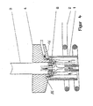
- FIG. 4 shows a further embodiment of the Plasma manipulator according to the invention shown.
- the ICP burner tube is 1 to brought up to the plasma manipulator 4, can for example, directly on the plasma manipulator 4 issue.
- An inert gas flows through the nozzle 3, for example argon, which in Figure 4 from bottom to top flowing towards the plasma torch.
- the inert gas flow occurs through the opening of the panel 8 to the outside and meets there concentric to the carrier gas stream of the plasma torch.
- the plasma torch is pushed apart in a funnel shape and enters an annularly shaped suction device 16 on. Both the inert gas and also the carrier gas of the plasma torch and the Aspirated aerosol residues.
- the cooled gas can then cleaned and used again as a carrier gas. Because the ICP burner tube 1, the orifice 8 and the annular gap 16 essentially encloses, the plasma flame practically no longer with the ambient atmosphere in Contact us, so that disturbing interference excluded are.
- the thermal energy of the plasma torch is preferred by water cooling the plasma manipulator 4 dissipated.
- the study of cadmium Plasma torch can be kept very short, so that only the hotter part is being analyzed while analyzing Sodium plasma torch can be kept longer, so that the cooler areas with the sodium emission lines can be viewed optically.
Landscapes
- Physics & Mathematics (AREA)
- Health & Medical Sciences (AREA)
- Engineering & Computer Science (AREA)
- Plasma & Fusion (AREA)
- Spectroscopy & Molecular Physics (AREA)
- General Health & Medical Sciences (AREA)
- Biochemistry (AREA)
- Analytical Chemistry (AREA)
- Chemical & Material Sciences (AREA)
- Life Sciences & Earth Sciences (AREA)
- General Physics & Mathematics (AREA)
- Immunology (AREA)
- Pathology (AREA)
- Nuclear Medicine, Radiotherapy & Molecular Imaging (AREA)
- Electromagnetism (AREA)
- Toxicology (AREA)
- Investigating, Analyzing Materials By Fluorescence Or Luminescence (AREA)
- Crystals, And After-Treatments Of Crystals (AREA)
- Plasma Technology (AREA)
Claims (16)
- Dispositif pour l'analyse spectrale d'émissions, comportant un plasma d'analyse contenant l'échantillon à analyser et un spectromètre approprié pour des mesures d'émission, caractérisé en ce qu'il est prévu un manipulateur à plasma (4), comportant un diaphragme refroidi (8) concentriquement à l'axe (7) et perpendiculairement à la direction de propagation du plasma et présentant un diamètre libre inférieur au diamètre du plasma, qui ne laisse traverser que la partie centrale (6) ou que la partie optique du plasma d'analyse et qui occulte la zone restante, et un dispositif d'observation (3) pour l'émission de rayonnement du volume de plasma ayant traversé.
- Dispositif selon la revendication 1, caractérisé en ce que le dispositif d'observation (3) est agencé sous un angle d'observation compris entre 10 et 170°, de préférence entre 45 et 135° par rapport à l'axe de propagation du plasma.
- Dispositif selon la revendication 1, caractérisé en ce que l'axe du dispositif d'observation (3) en particulier d'un manchon d'observation coïncide avec l'axe (7) du plasma d'analyse central ayant traversé ou de la partie optique.
- Dispositif pour l'analyse spectrale d'émission selon l'une quelconque des revendications précédentes, caractérisé en ce qu'une source de tension variable (U) est agencée entre le générateur de plasma d'analyse (1, 2) et le diaphragme refroidi.
- Dispositif pour l'analyse spectrale d'émission selon l'une quelconque des revendications précédentes, caractérisé en ce que sur le manipulateur à plasma (4) est prévu le diaphragme (8) avec une épaisseur comparable à son diamètre, et en ce que le volume d'observation présente un diamètre supérieur à celui du diaphragme.
- Dispositif pour l'analyse spectrale d'émission selon l'une quelconque des revendications précédentes, caractérisé en ce qu'il est prévu, entre le diaphragme (8) et le volume d'observation, en particulier au niveau du volume d'observation, des électrodes (9, 10) à titre de moyen pour générer un champ électrique et/ou magnétique, en particulier une bobine, dans l'espace adjacent au rayonnement de plasma occulté (6).
- Dispositif pour l'analyse spectrale d'émission selon l'une quelconque des revendications précédentes, caractérisé en ce que les électrodes (9, 10) ou les moyens sont alimenté(e)s en une tension alternative, et en ce que la preuve du signal dans le spectromètre s'effectue de façon synchrone avec la phase de la tension alternative.
- Dispositif pour l'analyse spectrale d'émission selon l'une quelconque des revendications précédentes, caractérisé en ce que le manipulateur à plasma (4) comprend, à l'emplacement de sortie du rayonnement de plasma central (6), un diaphragme avec un manchon tubulaire (12) pour brancher une pompe, et en ce que le manchon d'observation (3) est refermé de façon étanche aux gaz par une fenêtre optique (13).
- Dispositif pour l'analyse spectrale d'émission selon la revendication 6, caractérisé en ce que le côté aspiration de la pompe est relié au manchon tubulaire (12), et en ce que le côté pression de la pompe est ramené dans le plasma d'analyse, en particulier dans le courant de gaz de refroidissement.
- Dispositif pour l'analyse spectrale d'émission selon l'une quelconque des revendications précédentes, caractérisé en ce que le manipulateur à plasma (4) est un corps creux fabriqué en métal et traversé par de l'eau de refroidissement, et en ce que les diaphragmes (8, 11) sont fabriqués de préférence en graphite et sont enfoncés à la presse ou vissés.
- Dispositif pour l'analyse spectrale d'émission selon l'une quelconque des revendications précédentes, caractérisé en ce que le manchon d'observation (3) est pourvu d'un raccord à gaz de rinçage, de préférence pour le gaz porteur du plasma d'analyse, et est refermé de façon étanche aux gaz par une fenêtre optique (13).
- Dispositif pour l'analyse spectrale d'émission selon l'une quelconque des revendications précédentes, caractérisé en ce qu'un ou plusieurs manchons d'observation (3) sont agencés autour du volume d'observation, et en ce que l'un au moins comprend un guide d'ondes optiques.
- Dispositif pour l'analyse spectrale d'émission selon l'une quelconque des revendications précédentes, caractérisé en ce qu'il est prévu à l'intérieur du manipulateur à plasma (4) un perçage en alignement avec le manchon d'observation (3), perçage qui comprend un miroir concave dont l'axe s'étend à l'intérieur du manchon d'observation (3).
- Dispositif pour l'analyse spectrale d'émission selon l'une quelconque des revendications précédentes, caractérisé en ce que sur le manipulateur à plasma (4) sont prévus le diaphragme (8), une fenêtre optique (13) étanche aux gaz entre le diaphragme (8) et le dispositif d'observation (3), ainsi qu'une conduite d'amenée de gaz de rinçage (14) vers le volume entre le diaphragme (8) et la fenêtre optique (13), de sorte que le gaz de rinçage sort hors du diaphragme (8) en direction du plasma d'analyse.
- Dispositif pour l'analyse spectrale d'émission selon l'une quelconque des revendications précédentes, caractérisé en ce qu'il est prévu, aux alentours du diaphragme refroidi (8), des perçages dans le manipulateur à plasma (4), qui sont reliés au côté aspiration d'une pompe, et en ce que le côté pression de la pompe est ramené dans le plasma d'analyse ou dans le courant de gaz de refroidissement.
- Dispositif pour l'analyse spectrale d'émission selon la revendication 15, caractérisé en ce que le tube de guidage extérieur pour le gaz de plasma (1) est relié de façon sensiblement étanche au manipulateur à plasma (4) à l'extérieur des perçages pour la conduite d'aspiration de gaz de plasma (16).
Applications Claiming Priority (5)
| Application Number | Priority Date | Filing Date | Title |
|---|---|---|---|
| DE4409237 | 1994-03-18 | ||
| DE4409237 | 1994-03-18 | ||
| DE4419423A DE4419423A1 (de) | 1994-03-18 | 1994-06-03 | Plasma-Manipulator |
| DE4419423 | 1994-06-03 | ||
| PCT/EP1995/000447 WO1995025951A1 (fr) | 1994-03-18 | 1995-02-08 | Manipulateur a plasma |
Publications (2)
| Publication Number | Publication Date |
|---|---|
| EP0699300A1 EP0699300A1 (fr) | 1996-03-06 |
| EP0699300B1 true EP0699300B1 (fr) | 2002-01-09 |
Family
ID=25934831
Family Applications (1)
| Application Number | Title | Priority Date | Filing Date |
|---|---|---|---|
| EP95909686A Expired - Lifetime EP0699300B1 (fr) | 1994-03-18 | 1995-02-08 | Manipulateur a plasma |
Country Status (5)
| Country | Link |
|---|---|
| US (1) | US5731872A (fr) |
| EP (1) | EP0699300B1 (fr) |
| AT (1) | ATE211821T1 (fr) |
| AU (1) | AU1848995A (fr) |
| WO (1) | WO1995025951A1 (fr) |
Families Citing this family (6)
| Publication number | Priority date | Publication date | Assignee | Title |
|---|---|---|---|---|
| US9997325B2 (en) * | 2008-07-17 | 2018-06-12 | Verity Instruments, Inc. | Electron beam exciter for use in chemical analysis in processing systems |
| WO2010056921A2 (fr) * | 2008-11-14 | 2010-05-20 | Project Frog, Inc. | Panneau de construction intelligent multifonctions |
| EP2568276B1 (fr) | 2011-09-06 | 2016-11-23 | Spectro Analytical Instruments GmbH | Transfert d'émission de plasma et dispositif de modification |
| JP6339816B2 (ja) * | 2014-02-10 | 2018-06-06 | 株式会社Fuji | プラズマ処理判断システム |
| US10327319B1 (en) * | 2016-05-25 | 2019-06-18 | Perkinelmer Health Sciences, Inc. | Counterflow sample introduction and devices, systems and methods using it |
| KR20220058249A (ko) | 2020-10-30 | 2022-05-09 | 주식회사 엘지에너지솔루션 | 이차전지용 플라즈마 발생장치 및 그를 포함하는 라미네이션 시스템 |
Family Cites Families (3)
| Publication number | Priority date | Publication date | Assignee | Title |
|---|---|---|---|---|
| US4395091A (en) * | 1980-10-31 | 1983-07-26 | The Perkin-Elmer Corporation | Optical coupling device for use with a plasma emission spectrometer |
| JP2675561B2 (ja) * | 1987-12-18 | 1997-11-12 | 株式会社日立製作所 | プラズマ微量元素分折装置 |
| US5483337A (en) * | 1994-10-19 | 1996-01-09 | Barnard; Thomas W. | Spectrometer with selectable radiation from induction plasma light source |
-
1995
- 1995-02-08 AU AU18489/95A patent/AU1848995A/en not_active Abandoned
- 1995-02-08 US US08/549,851 patent/US5731872A/en not_active Expired - Lifetime
- 1995-02-08 EP EP95909686A patent/EP0699300B1/fr not_active Expired - Lifetime
- 1995-02-08 AT AT95909686T patent/ATE211821T1/de not_active IP Right Cessation
- 1995-02-08 WO PCT/EP1995/000447 patent/WO1995025951A1/fr not_active Ceased
Also Published As
| Publication number | Publication date |
|---|---|
| ATE211821T1 (de) | 2002-01-15 |
| WO1995025951A1 (fr) | 1995-09-28 |
| AU1848995A (en) | 1995-10-09 |
| EP0699300A1 (fr) | 1996-03-06 |
| US5731872A (en) | 1998-03-24 |
Similar Documents
| Publication | Publication Date | Title |
|---|---|---|
| DE69424301T2 (de) | Kontinuierlicher mikrowellenplasma-elementsensor in echtzeit | |
| EP1166328B1 (fr) | Dispositif d'admission de gaz destine a admettre un jet de gaz dirige et refroidi | |
| DE69026136T2 (de) | Spektroskopischer Plasmabrenner für Mikrowellenplasma | |
| DE112010000743B4 (de) | Detektor und Vorrichtung für einen Strahl geladener Teilchen mit einem solchen Detektor | |
| EP1082749B1 (fr) | Dispositif d'admission de gaz pour source d'ions | |
| DE69311124T2 (de) | Verfahren zur reduzierung von interferenzen in plasmaquellen-massenspektrometern | |
| DE19512793A1 (de) | Analysesystem und -verfahren | |
| DE3905303A1 (de) | Vorrichtung zur erzeugung eines plasmas durch mikrowellen | |
| DE112014001431T5 (de) | Verfahren und Vorrichtung zum Steuern eines Plasmas für eine Spektrometrie | |
| EP0364539B1 (fr) | Spectrometre d'absorption atomique | |
| EP0699300B1 (fr) | Manipulateur a plasma | |
| DE1489658A1 (de) | Vorrichtung zur Beschiessung eines Gegenstandes mit einem Elektronenstrahlenbuendel und Verfahren fuer diese Beschiessung zum Zwecke der Emission von Roentgenstrahlen durch diesen Gegenstand | |
| EP3717892A1 (fr) | Spectromètre d'émission d'étincelles et procédé pour le faire fonctionner | |
| DE1929429C3 (de) | Vorrichtung zur spektrochemischen Analyse eines Materials | |
| DE10354787B4 (de) | Verfahren und Vorrichtung zur Durchführung einer ortsaufgelösten Lokal- und Verteilungsanalyse und zur quantitativen Bestimmung von Elementkonzentrationen | |
| EP0401658B1 (fr) | Microscope à effet tunnel muni de dispositifs pour détecter les électrons provenant d'un échantillon | |
| DE2052669A1 (de) | Vorrichtung zur spektralanalytischen Untersuchung von Bereichen hoher Tempe ratur, insbesondere von geschmolzenen Me tallen | |
| EP1875212A1 (fr) | Procede et dispositif pour caracteriser une surface d'une piece a usiner | |
| DE19636716C2 (de) | Atomabsorptionsspektrometer | |
| EP0045362B1 (fr) | Appareil d'analyse spectrographique de la composition chimique de pièces métalliques | |
| DE69108763T2 (de) | Verfahren und Vorrichtung zum Einspritzen von Komponenten in Plasma zur "ICP-OES"-Analyse. | |
| DE2048862A1 (de) | Vorrichtung zur spektralphotometri sehen Analyse | |
| EP1953537A1 (fr) | Dispositif pour détecter ou guider des rayons x utilisant une optique pour rayons x | |
| DE4419423A1 (de) | Plasma-Manipulator | |
| DE2908350C2 (de) | Glimmentladungslampe zur qualitativen und quantitativen Spektralanalyse |
Legal Events
| Date | Code | Title | Description |
|---|---|---|---|
| PUAI | Public reference made under article 153(3) epc to a published international application that has entered the european phase |
Free format text: ORIGINAL CODE: 0009012 |
|
| 17P | Request for examination filed |
Effective date: 19951027 |
|
| AK | Designated contracting states |
Kind code of ref document: A1 Designated state(s): AT BE CH DE DK ES FR GB GR IT LI NL SE |
|
| 17Q | First examination report despatched |
Effective date: 20000705 |
|
| GRAG | Despatch of communication of intention to grant |
Free format text: ORIGINAL CODE: EPIDOS AGRA |
|
| GRAG | Despatch of communication of intention to grant |
Free format text: ORIGINAL CODE: EPIDOS AGRA |
|
| GRAH | Despatch of communication of intention to grant a patent |
Free format text: ORIGINAL CODE: EPIDOS IGRA |
|
| GRAH | Despatch of communication of intention to grant a patent |
Free format text: ORIGINAL CODE: EPIDOS IGRA |
|
| GRAA | (expected) grant |
Free format text: ORIGINAL CODE: 0009210 |
|
| REG | Reference to a national code |
Ref country code: GB Ref legal event code: IF02 |
|
| AK | Designated contracting states |
Kind code of ref document: B1 Designated state(s): AT BE CH DE DK ES FR GB GR IT LI NL SE |
|
| PG25 | Lapsed in a contracting state [announced via postgrant information from national office to epo] |
Ref country code: NL Free format text: LAPSE BECAUSE OF FAILURE TO SUBMIT A TRANSLATION OF THE DESCRIPTION OR TO PAY THE FEE WITHIN THE PRESCRIBED TIME-LIMIT Effective date: 20020109 Ref country code: IT Free format text: LAPSE BECAUSE OF FAILURE TO SUBMIT A TRANSLATION OF THE DESCRIPTION OR TO PAY THE FEE WITHIN THE PRE;WARNING: LAPSES OF ITALIAN PATENTS WITH EFFECTIVE DATE BEFORE 2007 MAY HAVE OCCURRED AT ANY TIME BEFORE 2007. THE CORRECT EFFECTIVE DATE MAY BE DIFFERENT FROM THE ONE RECORDED.SCRIBED TIME-LIMIT Effective date: 20020109 Ref country code: GR Free format text: LAPSE BECAUSE OF FAILURE TO SUBMIT A TRANSLATION OF THE DESCRIPTION OR TO PAY THE FEE WITHIN THE PRESCRIBED TIME-LIMIT Effective date: 20020109 |
|
| REF | Corresponds to: |
Ref document number: 211821 Country of ref document: AT Date of ref document: 20020115 Kind code of ref document: T |
|
| REG | Reference to a national code |
Ref country code: CH Ref legal event code: NV Representative=s name: LUCHS & PARTNER PATENTANWAELTE Ref country code: CH Ref legal event code: EP |
|
| GBT | Gb: translation of ep patent filed (gb section 77(6)(a)/1977) |
Effective date: 20020110 |
|
| PG25 | Lapsed in a contracting state [announced via postgrant information from national office to epo] |
Ref country code: AT Free format text: LAPSE BECAUSE OF NON-PAYMENT OF DUE FEES Effective date: 20020208 |
|
| REF | Corresponds to: |
Ref document number: 59509986 Country of ref document: DE Date of ref document: 20020214 |
|
| PG25 | Lapsed in a contracting state [announced via postgrant information from national office to epo] |
Ref country code: BE Free format text: LAPSE BECAUSE OF NON-PAYMENT OF DUE FEES Effective date: 20020228 |
|
| PG25 | Lapsed in a contracting state [announced via postgrant information from national office to epo] |
Ref country code: SE Free format text: LAPSE BECAUSE OF FAILURE TO SUBMIT A TRANSLATION OF THE DESCRIPTION OR TO PAY THE FEE WITHIN THE PRESCRIBED TIME-LIMIT Effective date: 20020409 Ref country code: DK Free format text: LAPSE BECAUSE OF FAILURE TO SUBMIT A TRANSLATION OF THE DESCRIPTION OR TO PAY THE FEE WITHIN THE PRESCRIBED TIME-LIMIT Effective date: 20020409 |
|
| NLV1 | Nl: lapsed or annulled due to failure to fulfill the requirements of art. 29p and 29m of the patents act | ||
| ET | Fr: translation filed | ||
| PG25 | Lapsed in a contracting state [announced via postgrant information from national office to epo] |
Ref country code: ES Free format text: LAPSE BECAUSE OF FAILURE TO SUBMIT A TRANSLATION OF THE DESCRIPTION OR TO PAY THE FEE WITHIN THE PRESCRIBED TIME-LIMIT Effective date: 20020730 |
|
| BERE | Be: lapsed |
Owner name: SPECTRO ANALYTICAL INSTRUMENTS G.- FUR ANALYTISCH Effective date: 20020228 |
|
| PLBE | No opposition filed within time limit |
Free format text: ORIGINAL CODE: 0009261 |
|
| STAA | Information on the status of an ep patent application or granted ep patent |
Free format text: STATUS: NO OPPOSITION FILED WITHIN TIME LIMIT |
|
| 26N | No opposition filed | ||
| NLV1 | Nl: lapsed or annulled due to failure to fulfill the requirements of art. 29p and 29m of the patents act | ||
| REG | Reference to a national code |
Ref country code: CH Ref legal event code: PFA Owner name: SPECTRO ANALYTICAL INSTRUMENTS GMBH Free format text: SPECTRO ANALYTICAL INSTRUMENTS GESELLSCHAFT FUER ANALYTISCHE MESSGERAETE MBH#BOSCHSTRASSE 10#D-47533 KLEVE (DE) -TRANSFER TO- SPECTRO ANALYTICAL INSTRUMENTS GMBH#BOSCHSTRASSE 10#47533 KLEVE (DE) |
|
| REG | Reference to a national code |
Ref country code: FR Ref legal event code: TP Ref country code: FR Ref legal event code: CD |
|
| REG | Reference to a national code |
Ref country code: GB Ref legal event code: 732E Free format text: REGISTERED BETWEEN 20100204 AND 20100211 |
|
| PGFP | Annual fee paid to national office [announced via postgrant information from national office to epo] |
Ref country code: DE Payment date: 20140224 Year of fee payment: 20 Ref country code: CH Payment date: 20140224 Year of fee payment: 20 |
|
| PGFP | Annual fee paid to national office [announced via postgrant information from national office to epo] |
Ref country code: FR Payment date: 20140220 Year of fee payment: 20 |
|
| PGFP | Annual fee paid to national office [announced via postgrant information from national office to epo] |
Ref country code: GB Payment date: 20140224 Year of fee payment: 20 |
|
| REG | Reference to a national code |
Ref country code: DE Ref legal event code: R071 Ref document number: 59509986 Country of ref document: DE |
|
| REG | Reference to a national code |
Ref country code: CH Ref legal event code: PL |
|
| REG | Reference to a national code |
Ref country code: GB Ref legal event code: PE20 Expiry date: 20150207 |
|
| PG25 | Lapsed in a contracting state [announced via postgrant information from national office to epo] |
Ref country code: GB Free format text: LAPSE BECAUSE OF EXPIRATION OF PROTECTION Effective date: 20150207 |