EP0699342B1 - Procede de modulation par sauts de frequence et equipement de station de base - Google Patents
Procede de modulation par sauts de frequence et equipement de station de base Download PDFInfo
- Publication number
- EP0699342B1 EP0699342B1 EP95912272A EP95912272A EP0699342B1 EP 0699342 B1 EP0699342 B1 EP 0699342B1 EP 95912272 A EP95912272 A EP 95912272A EP 95912272 A EP95912272 A EP 95912272A EP 0699342 B1 EP0699342 B1 EP 0699342B1
- Authority
- EP
- European Patent Office
- Prior art keywords
- signal
- base station
- time
- frequency
- carrier frequency
- Prior art date
- Legal status (The legal status is an assumption and is not a legal conclusion. Google has not performed a legal analysis and makes no representation as to the accuracy of the status listed.)
- Expired - Lifetime
Links
Images

Classifications
-
- H—ELECTRICITY
- H04—ELECTRIC COMMUNICATION TECHNIQUE
- H04W—WIRELESS COMMUNICATION NETWORKS
- H04W88/00—Devices specially adapted for wireless communication networks, e.g. terminals, base stations or access point devices
- H04W88/08—Access point devices
-
- H—ELECTRICITY
- H04—ELECTRIC COMMUNICATION TECHNIQUE
- H04B—TRANSMISSION
- H04B1/00—Details of transmission systems, not covered by a single one of groups H04B3/00 - H04B13/00; Details of transmission systems not characterised by the medium used for transmission
- H04B1/69—Spread spectrum techniques
- H04B1/713—Spread spectrum techniques using frequency hopping
-
- H—ELECTRICITY
- H04—ELECTRIC COMMUNICATION TECHNIQUE
- H04B—TRANSMISSION
- H04B7/00—Radio transmission systems, i.e. using radiation field
- H04B7/02—Diversity systems; Multi-antenna system, i.e. transmission or reception using multiple antennas
- H04B7/12—Frequency diversity
-
- H—ELECTRICITY
- H04—ELECTRIC COMMUNICATION TECHNIQUE
- H04B—TRANSMISSION
- H04B7/00—Radio transmission systems, i.e. using radiation field
- H04B7/24—Radio transmission systems, i.e. using radiation field for communication between two or more posts
- H04B7/26—Radio transmission systems, i.e. using radiation field for communication between two or more posts at least one of which is mobile
- H04B7/2643—Radio transmission systems, i.e. using radiation field for communication between two or more posts at least one of which is mobile using time-division multiple access [TDMA]
- H04B7/265—Radio transmission systems, i.e. using radiation field for communication between two or more posts at least one of which is mobile using time-division multiple access [TDMA] for channel frequency control
-
- H—ELECTRICITY
- H04—ELECTRIC COMMUNICATION TECHNIQUE
- H04W—WIRELESS COMMUNICATION NETWORKS
- H04W48/00—Access restriction; Network selection; Access point selection
- H04W48/08—Access restriction or access information delivery, e.g. discovery data delivery
- H04W48/12—Access restriction or access information delivery, e.g. discovery data delivery using downlink control channel
Definitions
- the present invention relates to a method for implementing frequency hopping in a base station of a digital cellular radio system, in which base station a first signal modulated by base band data signal is transmitted on a certain carrier frequency, which signal is divided in the time domain into several time slots of which one time slot transmits the common control channel of the base station equipment and the other time slots information regarding different connections.
- the quality of a radio channel varies as a function of time and place.
- a transmitting antenna and a receiving antenna are not within sight of each other due to obstacles formed by terrain or buildings in the line of sight, and thus the signal detected at the receiver is a sum of beams that have travelled different paths and have been reflected from obstacles and that are, further, with different phases.
- the sum of several signals with different phases follows the Rayleigh distribution in cases of randomly distributed phases.
- Signal fading is, furthermore, dependent on the frequency of the signal. Thus, if a frequency difference between two signals is great enough, their fadings do not correlate. A difference of 1 MHz, for example, is large enough for signal fadings to be independent of each other.
- Frequency hopping means that the transmission frequency used in a connection is changed at predetermined intervals. Due to frequency hopping, the transmission quality can be improved especially in situations in which the terminal equipment moves very slowly or not at all as is often the case with, for example, hand-held phones.
- the method is also advantageous in distributing the interference caused by the radio connection onto several frequencies, in which case momentary interference on any one frequency will remain small.
- WO-A-9322849 discloses a digital time and frequency division multiple access cellular network wherein the traffic channels use frequency hopping. During time slots used for the control channel, all available frequencies other than the control channel frequency belonging to the hopping sequence. In other time slots all available frequencies belong to the sequence.
- the base station equipment In the prior art solutions, if frequency hopping has been desired in a cell served by a base station, the base station equipment must have been provided with at least two complete transceiver units which contain base band sections and radio frequency sections. Each unit as such can form an independent base station, but to implement frequency hopping several of them have been required in the same cell. This has resulted in that the base station equipment capable of frequency hopping has been disproportionately large in small cells in comparison with the capacity needed, and the implementation of frequency hopping has thus required heavy investments.
- the second signal is divided in the time domain into several time slots, each of which transmits the same information as the first signal, except the time slot which transmits the common control channel of the base band equipment, and which carrier frequency is changed time-slot-specifically so that the frequency is either the same as the carrier frequency or different than that.
- the invention also relates to base station equipment in a digital cellular radio system, said equipment comprising means for generating a base band data signal, a first means for transmitting a signal modulated by a certain carrier frequency, and said signal being divided in the time domain into several time slots of which one transmits the common control channel of the base station equipment and the other time slots information regarding different connections, an antenna, a second means for transmitting a signal modulated by a carrier frequency, elements for changing the carrier frequency used in the second means time-slot-specifically, and means for distributing the basic band signal to the first and the second transmitting means so that the signal transmitted by the second means is divided in the time domain into several time slots; characterized in that said second means transmits in each time slot the same information as the signal transmitted by the first means except the time slot that transmits the common control channel of the base station equipment.
- the method of the invention can be applied for implementing frequency hopping in a cell comprising one transceiver unit.
- the base station in accordance with the invention can be built similarly to a conventional non-hopping base station, the only necessary changes being in the RF section of the transmitter. Only one base band section is needed. If frequency hopping is unnecessary, the base station of the invention can easily implement space diversity in a direction from the base station to the mobile station. The use of frequencies can be optimized so that frequency hopping is utilized only on weak connections.
- the invention can thus be applied in the base station equipment of digital cellular radio systems such as the GSM system, for instance.
- the invention will be described when applied in a time slot structure of the type used in the GSM system, but without being restricted to that.
- Figure 1 illustrates the implementation of time-slot-specific frequency hopping.
- the horizontal axis of the figure represents time, and the vertical axis represents frequency.
- the figure shows the frequency changes of one channel according to time slots.
- the base station changes carrier frequency at the beginning of every time slot, but the frequency is not changed during the time slot.
- the frequency is changed according to a predetermined sequence, in which case the receiver can monitor the hopping and receive the information contained in each time slot on a correct frequency.
- each connection can have a hop sequence of its own, in which case the frequencies used in the time slots do not overlap.
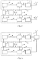
- FIG. 2 is a block diagram of the structure of a base station equipment in which the method of the invention is applied.
- the equipment contains means 15 for generating a base band signal.
- the output 16 of said means 15 is connected to two transmitter units 10,18 with the aid of a base band signal divider.
- the first transmitter unit 10 contains a carrier generator 12 whose output 26 is connected to a modulating means 13 whose second input is a base band data signal from the base band signal divider 17.
- the time division carrier signal 23 modulated by a base band signal is fed via an output amplifier 14 to an antenna 11.
- the first signal of the transmitter unit contains the common control channel BCCH of a cell served by a base station. By listening to that signal, mobile stations obtain information of the base station so that they can contact it, if necessary.
- FIG. 4a illustrates the structure of a GSM frame in which the first time slot 0 contains the BCCH channel, the second time slot 1 a dummy burst, time slots 2, 3, 4 and 6 data information, and time slots 5 and 7 a dummy burst.
- the carrier frequency of the transmitter 10 is marked with f1, and it is constant.
- the second transmitter unit 18 correspondingly contains a carrier generator 20 whose output 27 is connected to modulation means 21 whose second input is the base band data signal from the base band signal divider 17, i.e. the same signal as in the input of the first transmitter unit.
- the time division carrier signal 24 modulated by the base band signal is supplied via output amplifier 14 to an antenna 19.
- the signal of the second transmitter unit does not contain the common control channel BCCH, and the said time slot is not transmitted. In the other time slots 1-7 data belonging to some connection is transmitted, or the transmitter is switched off, if the time slot is not in use.
- the carrier frequency used by the second transmitter unit hops time-slot-specifically under the control of means 25 so that with each connection (i.e. time slot) the frequency changes according to a predetermined sequence.
- the carrier frequency of the second transmitter unit can momentarily be the same as the frequency f1 used by the first transmitter unit.
- the second transmitter unit when both of the transmitter units are on the same frequency, the second transmitter unit is switched off to avoid simultaneous transmission.
- the second transmitter unit can be controlled time-slot-specifically so that frequency hopping is only performed in certain time slots. If two antennas are in use in connections not applying frequency hopping, both transmitters transmit the same signal on the same frequency, and space diversity is obtained.
- Frequency use can be optimized so that frequency hopping is only applied to poor quality connections.
- signal strength as well as bit error and signal-to-noise ratios can be used as standards.
- FIG. 3 is a block diagram representation of an alternative structure of a base station equipment realizing the method of the invention.
- the equipment contains means 30 for combining signals from two transmitter units 10, 18 for transmitting via one antenna 11.
- the operation of a base station such as the one in figure 3 is similar to the above except that when one antenna is used, the second transmitter unit is switched off in cases where its carrier frequency is the same as the frequency of the first transmitter unit.
- the exemplary base stations also contain components other than those described, such as filters and divider amplifiers, but due to reasons of clarity they have been omitted from the figure as they are not essential to the present invention.
- figure 4a illustrates a frame structure transmitted by the first transmitter unit, the first time slot 0 containing the BCCH channel, time slots 2, 3, 4 and 6 containing data information (C1-C4), and time slots 1, 5 and 7 containing a dummy burst (B1-B3).
- the carrier frequency of the first transmitter is indicated by f1, and it is constant.
- Figure 4b illustrates a frame structure transmitted by the second transmitter unit.
- the transmitter unit utilizes three different frequencies, f2, f3 and f4 in frequency hopping.
- the number of frequencies can, of course, be something else in practice.
- connections C1, C2 and C4 using time slots 2, 3 and 6 employ frequency hopping, but connection C3 using time slot 4 does not hop.
- the second transmitter unit transmits a signal in time slots 2, 3 and 6 as shown by the figure, using at each moment of time one of the said carrier frequencies f2-f4.
- the second transmitter unit can, depending on the application, also use the frequency f1 of the first transmitter unit.
- the frequency used at each connection and each moment of time depends on the chosen hopping sequence which is specific for each connection.
- the second transmitter unit can, for example, transmit a frame in accordance with figure 4b so that time slot 2 uses frequency f2, time slot 3 frequency f3 and time slot 6 frequency f4. In the next frame the time slots are changed so that time slot 2 uses frequency f3, time slot 3 frequency f4 and time slot 6 frequency f3.
- the frequencies of the time slots are independent of each other, and they can also be the same.
- the second transmitter unit is able to transmit on non-hopping connections the time slot in question on the same frequency as the first transmitter unit in which case space diversity is achieved at the transmitting end.
- the second transmitter unit can thus transmit the signal of connection C4 in time slot 4 on a frequency f1.
- the second transmitter unit can be switched off if the frequencies of the transmitter units are the same; this can be done to avoid simultaneous transmission.
Landscapes
- Engineering & Computer Science (AREA)
- Computer Networks & Wireless Communication (AREA)
- Signal Processing (AREA)
- Mobile Radio Communication Systems (AREA)
- Transceivers (AREA)
Claims (12)
- Equipement de station de base dans un système de radiotéléphonie cellulaire numérique, ledit équipement comportant un moyen (15) pour générer un signal (20) de données en bande de base, un premier moyen (10) pour transmettre un signal (23) modulé par une certaine fréquence porteuse, et ledit signal étant réparti dans la dimension temporelle en plusieurs franches de temps dont l'une transmet la voie de commande commune (BCCH) de l'équipement de station de base et les autres tranches de temps transmettent des informations concernant des connexions différentes, une antenne (11), un deuxième moyen (18) pour transmettre un signal (24) modulé par une fréquence porteuse, des éléments (25) pour modifier la fréquence porteuse utilisée dans le deuxième moyen (18) d'une manière spécifique à chaque tranche de temps, et un moyen (17) pour répartir le signal (20) en bande de base entre le premier et le deuxième moyens de transmission (10, 18) de façon que le signal transmis par le deuxième moyen (18) soit réparti dans la dimension temporelle entre plusieurs franches de temps ;
caractérisé en ce que ledit deuxième moyen (18) transmet dans chaque tranche de temps les mêmes informations que le signal transmis par le premier moyen (10), à l'exception de la franche de temps qui transmet la voie de commande commune (BCCH), de l'équipement de station de base. - Equipement selon la revendication 1, caractérisé en ce que le premier et le deuxième moyens (10, 18) comprennent des moyens (12, 20) pour générer une onde porteuse, des moyens (13, 21) pour moduler l'onde porteuse par un signal en bande de base, et des moyens (14, 22) pour amplifier le signal modulé.
- Equipement selon la revendication 1, caractérisé en ce que l'équipement comprend une deuxième antenne (19) connectée au moyen d'amplification (22).
- Equipement selon la revendication 1, caractérisé en ce que l'équipement comprend un moyen (30) pour combiner des signaux provenant de deux émetteurs (10, 18) et destinés à être transmis par l'intermédiaire d'une seule antenne (11).
- Equipement selon la revendication 1, caractérisé en ce que des éléments (25) modifient selon une séquence prédéterminée la fréquence porteuse employée par le deuxième moyen (18).
- Equipement selon les revendications 4 et 5, caractérisé en ce que les éléments (25) arrêtent le deuxième moyen (18) lorsque la fréquence indiquée par la séquence est la même que la fréquence utilisée par le premier moyen (10).
- Procédé pour mettre en oeuvre des sauts de fréquence dans une station de base d'un système de radiotéléphonie cellulaire numérique, station de base dans laquelle un premier signal (23) modulé par un signal (16) de données en bande de base est transmis sur une certaine fréquence porteuse (26), lequel signal est divisé dans la dimension temporelle en plusieurs tranches de temps dont une première franche de temps transmet la voie de commande commune (BCCH) de l'équipement de station de base et les autres tranches de temps transmettent des informations concernant des connexions différentes ; et dans lequel la station de base transmet en outre sur une certaine fréquence porteuse (27) un deuxième signal (24) modulé par le même signal (16) de données en bande de base, dans lequel le deuxième signal (24) est divisé dans la dimension temporelle en plusieurs tranches de temps ; caractérisé en ce que chaque tranche de temps dudit deuxième signal transmet les mêmes informations que le premier signal (23), à l'exception de la franche de temps qui transmet la voie de commande commune de l'équipement en bande de base, et laquelle fréquence porteuse (27) est modifiée d'une manière spécifique pour chaque tranche de temps de façon que la fréquence soit identique à la fréquence porteuse (26) ou différente de celle-ci.
- Procédé selon la revendication 7, caractérisé en ce que la fréquence porteuse (27) est modifiée d'une manière spécifique de chaque tranche de temps, en suivant une séquence prédéterminée.
- Procédé selon la revendication 7, caractérisé en ce que le premier signal et le deuxième signal sont tous deux transmis par l'intermédiaire de leur propre antenne respective.
- Procédé selon la revendication 7, caractérisé en ce que le premier signal et le deuxième signal sont tous deux transmis par l'intermédiaire de la même antenne.
- Procédé selon les revendications 7 et 10, caractérisé en ce que, si la fréquence porteuse (27) indiquée par la séquence et utilisée par le deuxième signal est la même dans chaque franche de temps que la fréquence porteuse utilisée par le premier signal (26), le deuxième signal n'est pas transmis.
- Procédé selon la revendication 7, caractérisé en ce que le deuxième signal (24) est transmis d'une manière spécifique de chaque tranche de temps lorsque la qualité du signal transmis au cours de la tranche de temps est inférieure, à l'extrémité réceptrice, à une valeur de seuil prédéterminée.
Applications Claiming Priority (3)
| Application Number | Priority Date | Filing Date | Title |
|---|---|---|---|
| FI941289A FI941289A7 (fi) | 1994-03-18 | 1994-03-18 | Menetelmä taajuushyppelyn toteuttamiseksi ja tukiasemalaitteisto |
| FI941289 | 1994-03-18 | ||
| PCT/FI1995/000142 WO1995026040A2 (fr) | 1994-03-18 | 1995-03-16 | Procede de modulation par sauts de frequence et equipement de station de base |
Publications (2)
| Publication Number | Publication Date |
|---|---|
| EP0699342A1 EP0699342A1 (fr) | 1996-03-06 |
| EP0699342B1 true EP0699342B1 (fr) | 2000-05-31 |
Family
ID=8540346
Family Applications (1)
| Application Number | Title | Priority Date | Filing Date |
|---|---|---|---|
| EP95912272A Expired - Lifetime EP0699342B1 (fr) | 1994-03-18 | 1995-03-16 | Procede de modulation par sauts de frequence et equipement de station de base |
Country Status (10)
| Country | Link |
|---|---|
| US (1) | US5719857A (fr) |
| EP (1) | EP0699342B1 (fr) |
| JP (1) | JP3065663B2 (fr) |
| CN (1) | CN1077362C (fr) |
| AT (1) | ATE193627T1 (fr) |
| AU (1) | AU688878B2 (fr) |
| DE (1) | DE69517266T2 (fr) |
| FI (1) | FI941289A7 (fr) |
| NO (1) | NO311547B1 (fr) |
| WO (1) | WO1995026040A2 (fr) |
Cited By (1)
| Publication number | Priority date | Publication date | Assignee | Title |
|---|---|---|---|---|
| US7092736B2 (en) | 2002-01-17 | 2006-08-15 | Siemens Aktiengesellschaft | Radio communication system |
Families Citing this family (35)
| Publication number | Priority date | Publication date | Assignee | Title |
|---|---|---|---|---|
| DE19617301A1 (de) * | 1996-04-30 | 1997-11-06 | Alcatel Mobile Comm Deutsch | Neuordnen von Frequenzsprung-Gruppen für eine FDM-/TDM-Funkübertragung bei hoher Verkehrslast |
| DE19623279C1 (de) * | 1996-06-11 | 1997-12-11 | Nokia Mobile Phones Ltd | Schnurloses Telekommunikationsverfahren |
| GB2319928A (en) * | 1996-10-30 | 1998-06-03 | Motorola Ltd | Combined beacon and traffic channel transmission |
| FI104525B (fi) * | 1996-11-13 | 2000-02-15 | Nokia Networks Oy | Taajuushyppelymenetelmä ja radiojärjestelmä |
| GB2324932B (en) * | 1997-05-02 | 2002-03-06 | Motorola Ltd | Communication system having diversity in an orthogonal frequency division multiplexing environment and operating method therefor |
| US6011786A (en) * | 1997-06-06 | 2000-01-04 | Ericsson Inc. | Systems and methods for control channel communication in cellular radiotelephone systems |
| US5999519A (en) * | 1997-07-28 | 1999-12-07 | Geo-Com, Incorporated | Dual channel high speed wireless data transfer device |
| GB2328583A (en) * | 1997-08-23 | 1999-02-24 | Motorola Ltd | Frequency hopping in a TDMA communications system |
| US6173005B1 (en) * | 1997-09-04 | 2001-01-09 | Motorola, Inc. | Apparatus and method for transmitting signals in a communication system |
| KR100255320B1 (ko) | 1997-12-29 | 2000-05-01 | 윤종용 | 주파수 도약/부호 분할 다중 접속시스템의 기지국시스템 |
| FI974646L (fi) * | 1997-12-30 | 1999-07-01 | Nokia Networks Oy | Häiriöiden tasoittaminen matkaviestinjärjestelmässä |
| US7079584B2 (en) | 1998-08-10 | 2006-07-18 | Kamilo Feher | OFDM, CDMA, spread spectrum, TDMA, cross-correlated and filtered modulation |
| US6470055B1 (en) | 1998-08-10 | 2002-10-22 | Kamilo Feher | Spectrally efficient FQPSK, FGMSK, and FQAM for enhanced performance CDMA, TDMA, GSM, OFDN, and other systems |
| US7548787B2 (en) * | 2005-08-03 | 2009-06-16 | Kamilo Feher | Medical diagnostic and communication system |
| JP2000092560A (ja) * | 1998-09-11 | 2000-03-31 | Nec Saitama Ltd | 無線基地局装置およびphs公衆基地局装置ならびに移動通信方法 |
| GB9827015D0 (en) * | 1998-12-08 | 1999-02-03 | Nokia Telecommunications Oy | A transmitter in a mobile communications system |
| US7260369B2 (en) * | 2005-08-03 | 2007-08-21 | Kamilo Feher | Location finder, tracker, communication and remote control system |
| US6639938B1 (en) | 1999-09-23 | 2003-10-28 | Northrop Grumman Corporation | Method for dynamically routing frequency hopping signals in a multiple carrier communications system |
| US7177287B1 (en) * | 2000-01-05 | 2007-02-13 | Advanded Micro Devices, Inc. | System and method for concurrent wireless voice and data communications |
| SE516337C2 (sv) * | 2000-02-25 | 2001-12-17 | Ericsson Telefon Ab L M | Radiosändarsystem, mottagningssystem och förfaranden relaterade till frekvenshoppning |
| DE60103459T2 (de) * | 2000-08-02 | 2005-08-04 | Lucent Technologies Inc. | Verfahren zur Verbesserung der Leistung eines GSM Erzeuger von Frequenzsprungsequenzen für Kanälen mit halb und viertel Rat |
| GB0031619D0 (en) * | 2000-12-27 | 2001-02-07 | Koninkl Philips Electronics Nv | Method and apparatus for synchronising frequency hopping transceivers |
| US7145934B2 (en) * | 2001-03-03 | 2006-12-05 | Oxford Semiconductor Inc | Multichannel signal transmission and reception for bluetooth systems |
| DE10201642C1 (de) * | 2002-01-17 | 2003-12-11 | Siemens Ag | Funkkommunikationssystem |
| JP2004175052A (ja) * | 2002-11-29 | 2004-06-24 | Sony Corp | インクジェット被記録媒体、インクジェット画像形成方法及び印画物 |
| US20040141616A1 (en) * | 2003-01-17 | 2004-07-22 | Ibm Corporation | Security object with encrypted, spread spectrum data communications |
| EP1463358A1 (fr) * | 2003-03-28 | 2004-09-29 | Siemens Aktiengesellschaft | Procédé et station de base pour le transfert de données MBMS |
| US7231190B2 (en) * | 2003-07-28 | 2007-06-12 | Motorola, Inc. | Method and apparatus for terminating reception in a wireless communication system |
| EP1763148B1 (fr) * | 2005-06-14 | 2015-12-23 | Anritsu Corporation | Appareil et procédé de génération de signal d essai de dispositif de communication |
| US7668234B2 (en) | 2005-06-14 | 2010-02-23 | Anritsu Corp. | Test signal generating apparatus for communications equipment and test signal generating method for communications equipment |
| US7280810B2 (en) * | 2005-08-03 | 2007-10-09 | Kamilo Feher | Multimode communication system |
| US10084627B2 (en) * | 2006-07-10 | 2018-09-25 | Qualcomm Incorporated | Frequency hopping in an SC-FDMA environment |
| US10141974B2 (en) | 2015-03-17 | 2018-11-27 | Shai Waxman | High-capacity FHSS-MA devices and methods |
| CN106161305B (zh) * | 2015-03-27 | 2019-10-01 | 华为技术有限公司 | 一种降低干扰的方法和设备 |
| JP6640774B2 (ja) * | 2017-03-15 | 2020-02-05 | 株式会社東芝 | 送電装置および電力伝送システム |
Family Cites Families (11)
| Publication number | Priority date | Publication date | Assignee | Title |
|---|---|---|---|---|
| SE457184B (sv) * | 1987-04-03 | 1988-12-05 | Ericsson Telefon Ab L M | Foerfarande och utrustning foer synkronisering och oeverfoering av information i ett radiokommunikationsnaet |
| US5081641A (en) * | 1990-02-06 | 1992-01-14 | Motorola, Inc. | Interconnecting and processing system for facilitating frequency hopping |
| US5111454A (en) * | 1990-08-16 | 1992-05-05 | Motorola, Inc. | Digital cellular tdm system employing 6:1 packing of transcoded information |
| US5455962A (en) * | 1991-09-19 | 1995-10-03 | Motorola, Inc. | Performance through half-hopping and spatial diversity |
| SE9200607D0 (sv) * | 1992-02-28 | 1992-02-28 | Ericsson Telefon Ab L M | Communication methods and mean in a tdma cellular mobile radio system |
| SE470078B (sv) * | 1992-03-27 | 1993-11-01 | Ericsson Telefon Ab L M | Basstation för cellindelade frekvenshoppande TDMA- radiokommunikationssystem |
| FI97838C (fi) * | 1992-05-06 | 1997-02-25 | Nokia Telecommunications Oy | Solukkoverkkojärjestelmä |
| US5381443A (en) * | 1992-10-02 | 1995-01-10 | Motorola Inc. | Method and apparatus for frequency hopping a signalling channel in a communication system |
| DE69328406T2 (de) * | 1992-11-20 | 2000-09-14 | Ntt Mobile Communications Network Inc., Tokio/Tokyo | Frequenzdiversitysender und -Empfänger |
| US5812935A (en) * | 1993-04-17 | 1998-09-22 | Hughes Electronics | Cellular system employing base station transmit diversity according to transmission quality level |
| EP0650305A1 (fr) * | 1993-10-21 | 1995-04-26 | Koninklijke Philips Electronics N.V. | Système cellulaire radiomobile numérique et station de base pour la mise en oeuvre du système |
-
1994
- 1994-03-18 FI FI941289A patent/FI941289A7/fi unknown
-
1995
- 1995-03-16 WO PCT/FI1995/000142 patent/WO1995026040A2/fr not_active Ceased
- 1995-03-16 US US08/553,494 patent/US5719857A/en not_active Expired - Lifetime
- 1995-03-16 EP EP95912272A patent/EP0699342B1/fr not_active Expired - Lifetime
- 1995-03-16 DE DE69517266T patent/DE69517266T2/de not_active Expired - Fee Related
- 1995-03-16 AT AT95912272T patent/ATE193627T1/de not_active IP Right Cessation
- 1995-03-16 AU AU19520/95A patent/AU688878B2/en not_active Revoked
- 1995-03-16 JP JP7524402A patent/JP3065663B2/ja not_active Expired - Lifetime
- 1995-03-16 CN CN95190259A patent/CN1077362C/zh not_active Expired - Fee Related
- 1995-11-17 NO NO19954665A patent/NO311547B1/no not_active IP Right Cessation
Cited By (1)
| Publication number | Priority date | Publication date | Assignee | Title |
|---|---|---|---|---|
| US7092736B2 (en) | 2002-01-17 | 2006-08-15 | Siemens Aktiengesellschaft | Radio communication system |
Also Published As
| Publication number | Publication date |
|---|---|
| AU688878B2 (en) | 1998-03-19 |
| AU1952095A (en) | 1995-10-09 |
| FI941289A7 (fi) | 1995-09-19 |
| NO954665D0 (no) | 1995-11-17 |
| WO1995026040A3 (fr) | 1995-11-02 |
| CN1077362C (zh) | 2002-01-02 |
| CN1127575A (zh) | 1996-07-24 |
| JPH08510627A (ja) | 1996-11-05 |
| ATE193627T1 (de) | 2000-06-15 |
| NO311547B1 (no) | 2001-12-03 |
| EP0699342A1 (fr) | 1996-03-06 |
| US5719857A (en) | 1998-02-17 |
| DE69517266T2 (de) | 2000-10-19 |
| NO954665L (no) | 1996-01-17 |
| DE69517266D1 (de) | 2000-07-06 |
| FI941289A0 (fi) | 1994-03-18 |
| JP3065663B2 (ja) | 2000-07-17 |
| WO1995026040A2 (fr) | 1995-09-28 |
Similar Documents
| Publication | Publication Date | Title |
|---|---|---|
| EP0699342B1 (fr) | Procede de modulation par sauts de frequence et equipement de station de base | |
| US5210771A (en) | Multiple user spread-spectrum communication system | |
| KR960016647B1 (ko) | 주파수 호핑 티디엠에이(tdma) 무선 통신시스템의 기지국 | |
| US5838670A (en) | Point to multipoint radio access system | |
| US5187806A (en) | Apparatus and method for expanding cellular system capacity | |
| US5390166A (en) | Method for recovering a data signal using diversity in a radio frequency, time division multiple access communication system | |
| US6396823B1 (en) | Base station transceiver for frequency hopping code division multiple access system | |
| GB2295524A (en) | Beamed antenna system for a cellular radio base station | |
| EP0761045B1 (fr) | Procede permettant l'amelioration de la qualite des liaisons dans un systeme de radiocommunications cellulaire, et station de base associee | |
| EP0715786B1 (fr) | Equipement d'une station de base utilisant la reception en diversite | |
| US6738365B1 (en) | Method of improving connection quality and system capacity, and a cellular radio system | |
| EP0479744B1 (fr) | Méthode pour la réduction du risque de la réception pauvre dans un système de téléphonie mobile | |
| EP0976277B1 (fr) | Procede pour faciliter la mesure des niveaux de transmission, et station de base | |
| US6317610B1 (en) | Method of combining several signals, and base station | |
| AU711184B2 (en) | Method for realizing frequency hopping and a base station equipment | |
| CN1242118A (zh) | 改进连接质量与系统容量的方法和一个蜂窝无线电系统 |
Legal Events
| Date | Code | Title | Description |
|---|---|---|---|
| PUAI | Public reference made under article 153(3) epc to a published international application that has entered the european phase |
Free format text: ORIGINAL CODE: 0009012 |
|
| AK | Designated contracting states |
Kind code of ref document: A1 Designated state(s): AT BE CH DE DK ES FR GB GR IE IT LI LU MC NL PT SE |
|
| 17P | Request for examination filed |
Effective date: 19960304 |
|
| RAP1 | Party data changed (applicant data changed or rights of an application transferred) |
Owner name: NOKIA TELECOMMUNICATIONS OY |
|
| 17Q | First examination report despatched |
Effective date: 19980924 |
|
| GRAG | Despatch of communication of intention to grant |
Free format text: ORIGINAL CODE: EPIDOS AGRA |
|
| RIC1 | Information provided on ipc code assigned before grant |
Free format text: 6H 04B 7/26 A, 6H 01J 37/28 B |
|
| GRAG | Despatch of communication of intention to grant |
Free format text: ORIGINAL CODE: EPIDOS AGRA |
|
| GRAH | Despatch of communication of intention to grant a patent |
Free format text: ORIGINAL CODE: EPIDOS IGRA |
|
| GRAH | Despatch of communication of intention to grant a patent |
Free format text: ORIGINAL CODE: EPIDOS IGRA |
|
| RAP1 | Party data changed (applicant data changed or rights of an application transferred) |
Owner name: NOKIA NETWORKS OY |
|
| GRAA | (expected) grant |
Free format text: ORIGINAL CODE: 0009210 |
|
| AK | Designated contracting states |
Kind code of ref document: B1 Designated state(s): AT BE CH DE DK ES FR GB GR IE IT LI LU MC NL PT SE |
|
| PG25 | Lapsed in a contracting state [announced via postgrant information from national office to epo] |
Ref country code: GR Free format text: LAPSE BECAUSE OF NON-PAYMENT OF DUE FEES Effective date: 20000531 Ref country code: ES Free format text: THE PATENT HAS BEEN ANNULLED BY A DECISION OF A NATIONAL AUTHORITY Effective date: 20000531 |
|
| REF | Corresponds to: |
Ref document number: 193627 Country of ref document: AT Date of ref document: 20000615 Kind code of ref document: T |
|
| REG | Reference to a national code |
Ref country code: CH Ref legal event code: EP |
|
| REG | Reference to a national code |
Ref country code: CH Ref legal event code: NV Representative=s name: ICB INGENIEURS CONSEILS EN BREVETS SA |
|
| REF | Corresponds to: |
Ref document number: 69517266 Country of ref document: DE Date of ref document: 20000706 |
|
| REG | Reference to a national code |
Ref country code: IE Ref legal event code: FG4D |
|
| ET | Fr: translation filed | ||
| ITF | It: translation for a ep patent filed | ||
| PG25 | Lapsed in a contracting state [announced via postgrant information from national office to epo] |
Ref country code: PT Free format text: LAPSE BECAUSE OF FAILURE TO SUBMIT A TRANSLATION OF THE DESCRIPTION OR TO PAY THE FEE WITHIN THE PRESCRIBED TIME-LIMIT Effective date: 20000831 Ref country code: DK Free format text: LAPSE BECAUSE OF FAILURE TO SUBMIT A TRANSLATION OF THE DESCRIPTION OR TO PAY THE FEE WITHIN THE PRESCRIBED TIME-LIMIT Effective date: 20000831 |
|
| PG25 | Lapsed in a contracting state [announced via postgrant information from national office to epo] |
Ref country code: LU Free format text: LAPSE BECAUSE OF NON-PAYMENT OF DUE FEES Effective date: 20010316 Ref country code: IE Free format text: LAPSE BECAUSE OF NON-PAYMENT OF DUE FEES Effective date: 20010316 |
|
| PLBE | No opposition filed within time limit |
Free format text: ORIGINAL CODE: 0009261 |
|
| STAA | Information on the status of an ep patent application or granted ep patent |
Free format text: STATUS: NO OPPOSITION FILED WITHIN TIME LIMIT |
|
| PG25 | Lapsed in a contracting state [announced via postgrant information from national office to epo] |
Ref country code: MC Free format text: LAPSE BECAUSE OF NON-PAYMENT OF DUE FEES Effective date: 20010331 |
|
| 26N | No opposition filed | ||
| REG | Reference to a national code |
Ref country code: GB Ref legal event code: IF02 |
|
| REG | Reference to a national code |
Ref country code: IE Ref legal event code: MM4A |
|
| PGFP | Annual fee paid to national office [announced via postgrant information from national office to epo] |
Ref country code: SE Payment date: 20020306 Year of fee payment: 8 |
|
| PGFP | Annual fee paid to national office [announced via postgrant information from national office to epo] |
Ref country code: AT Payment date: 20020313 Year of fee payment: 8 |
|
| PGFP | Annual fee paid to national office [announced via postgrant information from national office to epo] |
Ref country code: NL Payment date: 20020328 Year of fee payment: 8 Ref country code: CH Payment date: 20020328 Year of fee payment: 8 |
|
| PGFP | Annual fee paid to national office [announced via postgrant information from national office to epo] |
Ref country code: BE Payment date: 20020527 Year of fee payment: 8 |
|
| PG25 | Lapsed in a contracting state [announced via postgrant information from national office to epo] |
Ref country code: AT Free format text: LAPSE BECAUSE OF NON-PAYMENT OF DUE FEES Effective date: 20030316 |
|
| PG25 | Lapsed in a contracting state [announced via postgrant information from national office to epo] |
Ref country code: SE Free format text: LAPSE BECAUSE OF NON-PAYMENT OF DUE FEES Effective date: 20030317 |
|
| PG25 | Lapsed in a contracting state [announced via postgrant information from national office to epo] |
Ref country code: LI Free format text: LAPSE BECAUSE OF NON-PAYMENT OF DUE FEES Effective date: 20030331 Ref country code: CH Free format text: LAPSE BECAUSE OF NON-PAYMENT OF DUE FEES Effective date: 20030331 Ref country code: BE Free format text: LAPSE BECAUSE OF NON-PAYMENT OF DUE FEES Effective date: 20030331 |
|
| BERE | Be: lapsed |
Owner name: *NOKIA NETWORKS OY Effective date: 20030331 |
|
| PG25 | Lapsed in a contracting state [announced via postgrant information from national office to epo] |
Ref country code: NL Free format text: LAPSE BECAUSE OF NON-PAYMENT OF DUE FEES Effective date: 20031001 |
|
| EUG | Se: european patent has lapsed | ||
| REG | Reference to a national code |
Ref country code: CH Ref legal event code: PL |
|
| NLV4 | Nl: lapsed or anulled due to non-payment of the annual fee |
Effective date: 20031001 |
|
| PGFP | Annual fee paid to national office [announced via postgrant information from national office to epo] |
Ref country code: FR Payment date: 20040309 Year of fee payment: 10 |
|
| PGFP | Annual fee paid to national office [announced via postgrant information from national office to epo] |
Ref country code: GB Payment date: 20040310 Year of fee payment: 10 |
|
| PGFP | Annual fee paid to national office [announced via postgrant information from national office to epo] |
Ref country code: DE Payment date: 20040325 Year of fee payment: 10 |
|
| PG25 | Lapsed in a contracting state [announced via postgrant information from national office to epo] |
Ref country code: IT Free format text: LAPSE BECAUSE OF NON-PAYMENT OF DUE FEES Effective date: 20050316 Ref country code: GB Free format text: LAPSE BECAUSE OF NON-PAYMENT OF DUE FEES Effective date: 20050316 |
|
| PG25 | Lapsed in a contracting state [announced via postgrant information from national office to epo] |
Ref country code: DE Free format text: LAPSE BECAUSE OF NON-PAYMENT OF DUE FEES Effective date: 20051001 |
|
| GBPC | Gb: european patent ceased through non-payment of renewal fee |
Effective date: 20050316 |
|
| PG25 | Lapsed in a contracting state [announced via postgrant information from national office to epo] |
Ref country code: FR Free format text: LAPSE BECAUSE OF NON-PAYMENT OF DUE FEES Effective date: 20051130 |
|
| REG | Reference to a national code |
Ref country code: FR Ref legal event code: ST Effective date: 20051130 |