EP0699352B1 - Serre-cable comprenant un dispositif de fixation de longueur reduite - Google Patents
Serre-cable comprenant un dispositif de fixation de longueur reduite Download PDFInfo
- Publication number
- EP0699352B1 EP0699352B1 EP94909277A EP94909277A EP0699352B1 EP 0699352 B1 EP0699352 B1 EP 0699352B1 EP 94909277 A EP94909277 A EP 94909277A EP 94909277 A EP94909277 A EP 94909277A EP 0699352 B1 EP0699352 B1 EP 0699352B1
- Authority
- EP
- European Patent Office
- Prior art keywords
- cable
- tail
- cylindrical
- clamp
- opening
- Prior art date
- Legal status (The legal status is an assumption and is not a legal conclusion. Google has not performed a legal analysis and makes no representation as to the accuracy of the status listed.)
- Expired - Lifetime
Links
- 230000007246 mechanism Effects 0.000 description 14
- 238000009434 installation Methods 0.000 description 3
- RYGMFSIKBFXOCR-UHFFFAOYSA-N Copper Chemical compound [Cu] RYGMFSIKBFXOCR-UHFFFAOYSA-N 0.000 description 2
- 230000008901 benefit Effects 0.000 description 2
- 238000010276 construction Methods 0.000 description 2
- 229910052802 copper Inorganic materials 0.000 description 2
- 239000010949 copper Substances 0.000 description 2
- 238000009413 insulation Methods 0.000 description 2
- 239000007787 solid Substances 0.000 description 2
- 229910000838 Al alloy Inorganic materials 0.000 description 1
- XAGFODPZIPBFFR-UHFFFAOYSA-N aluminium Chemical compound [Al] XAGFODPZIPBFFR-UHFFFAOYSA-N 0.000 description 1
- 229910052782 aluminium Inorganic materials 0.000 description 1
- 238000002788 crimping Methods 0.000 description 1
- 230000006872 improvement Effects 0.000 description 1
- 238000003780 insertion Methods 0.000 description 1
- 230000037431 insertion Effects 0.000 description 1
- 238000012986 modification Methods 0.000 description 1
- 230000004048 modification Effects 0.000 description 1
- 238000000926 separation method Methods 0.000 description 1
- 238000004804 winding Methods 0.000 description 1
Images

Classifications
-
- H—ELECTRICITY
- H01—ELECTRIC ELEMENTS
- H01R—ELECTRICALLY-CONDUCTIVE CONNECTIONS; STRUCTURAL ASSOCIATIONS OF A PLURALITY OF MUTUALLY-INSULATED ELECTRICAL CONNECTING ELEMENTS; COUPLING DEVICES; CURRENT COLLECTORS
- H01R4/00—Electrically-conductive connections between two or more conductive members in direct contact, i.e. touching one another; Means for effecting or maintaining such contact; Electrically-conductive connections having two or more spaced connecting locations for conductors and using contact members penetrating insulation
- H01R4/28—Clamped connections, spring connections
- H01R4/38—Clamped connections, spring connections utilising a clamping member acted on by screw or nut
- H01R4/40—Pivotable clamping member
-
- H—ELECTRICITY
- H01—ELECTRIC ELEMENTS
- H01R—ELECTRICALLY-CONDUCTIVE CONNECTIONS; STRUCTURAL ASSOCIATIONS OF A PLURALITY OF MUTUALLY-INSULATED ELECTRICAL CONNECTING ELEMENTS; COUPLING DEVICES; CURRENT COLLECTORS
- H01R4/00—Electrically-conductive connections between two or more conductive members in direct contact, i.e. touching one another; Means for effecting or maintaining such contact; Electrically-conductive connections having two or more spaced connecting locations for conductors and using contact members penetrating insulation
- H01R4/28—Clamped connections, spring connections
- H01R4/50—Clamped connections, spring connections utilising a cam, wedge, cone or ball also combined with a screw
Definitions
- the present invention relates to cable clamps, in particular for use with electrical cables of the type generally used in electrical distribution networks.
- cables In such networks it is known that ends of cables require connection in such a way as to provide a sound mechanical and electrical link between a cable and an external bar or plate, or alternately between two or more cables.
- Cables used in power distribution networks typically have stranded or solid cores of copper or aluminum and are generally of relatively large diameter and relatively difficult to work with.
- cable clamps which can be used to terminate a cable, for example to a bus bar, comprising a male jaw having a tail and an integral part-cylindrical head, and a female jaw having a tail and an integral yoke which defines a part-cylindrical socket.
- the head of the male jaw is received in the socket to permit relative pivotal movement between the jaws.
- a cable receiving opening extends diametrically through the head, and a cable receiving opening extends radially through the yoke. These openings are aligned in an open pivotal position of the jaws to permit insertion of the cable therethrough and substantially misaligned in a closed pivotal position cf the jaws to clamp the cable.
- the tails are clamped together to hold the jaws in the closed position.
- This invention provides an improvement for a cable clamp of the type comprising a first jaw having a first cable clamping portion and a first tail, and a second jaw having a second cable clamping portion and a second tail, in which the first jaw is pivotably mounted to the second jaw to move between a cable receiving open position, in which a cable can be inserted between the cable clamping portions, and a cable clamping closed position, in which the cable is clamped between the cable clamping portions.
- a first opening is provided in one of the tails
- a raised boss is provided on the other of the tails, positioned to fit within the first opening when the jaws are in the closed position.
- the raised boss comprises a threaded opening, and a threaded fastener is mounted in the threaded opening.
- This threaded fastener is shaped to apply closing forces on said one of the tails as the threaded fastener is rotated into the threaded opening. These closing forces tend to move the jaws to the closed position.
- two pairs of jaws are provided in a connector for connecting two cables together.
- the two female jaws are formed back-to-back as an integral elongate unit, whereby the connector in use lies substantially along the longitudinal axis of two cables joined end to end.
- This embodiment also includes two male jaws, one for engagement with each of the female jaws. Separate fastening means may be provided for each pair of jaws, or it may be arranged that a single fastening means acts to secure two or more of the pairs.
- a short threaded fastener or bolt can be used to close the cable clamp in many applications, without the need for special tools to pre-crimp the cable in the connector before the bolt is engaged. In this way, installation is made simpler, the need for special crimping or squeezing tools is reduced or eliminated, and the profile of the closed connector is reduced.
- This low-profile feature can eliminate protruding bolt ends when the clamp is closed, and makes it possible to use the clamp in in-line insulation equipment and in other situations. This low-profile advantage is also important in many other applications where space is limited, such as for switch gear equipment, panel boards, underground installations in insulated tubing, and the like.
- the preferred embodiments of this invention provide the further advantage that the connector may be disconnected and re-connected as necessary.
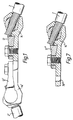
- Fig. 1 shows a partially sectional view of a first preferred embodiment 10 of this invention, which enables the ends of two cables 2, 2' to be electrically and mechanically connected to each other.
- this cable clamp 10 is symmetrical, having identical gripping mechanisms at each end, although in some embodiments the ends may be configured differently, and this will be discussed in detail later.
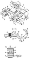
- Fig. 2 shows a perspective view of the first end cf the clamp 10 of Fig. 1 showing the gripping mechanism.
- the gripping mechanism includes a male jaw or member 12 and a female jaw or member 14.
- the male jaw 12 is shown in greater detail in Figs. 4 and 4a, and it includes a cylindrical head 16 which defines a cylindrical surface 18 centered on a cylinder axis 20 (Fig. 2).
- a first tail 22 extends radially away from the head 16, and the male jaw 12 is symmetrical about a plane of symmetry 24 (Fig. 4) which contains the cylinder axis 20.
- the male jaw 12 includes a first cable receiving opening 26 that, as shown in Fig. 4, is oriented at a skew angle A with respect to the first tail 22 and the plane of symmetry 24.
- the cable receiving opening 26 is adapted to receive the terminal portion of a cable, and the opening 26 opens out at both sides of the first tail 22 at a window 28 which passes completely through the tail 22.
- the tail 22 defines a free end 30 and a pair of spaced, parallel, opposed first surfaces 32 adjacent the free end 30. Both of these first surfaces 32 are parallel to the plane of symmetry 24.
- a fastener receiving opening 34 extends completely through the first tail 22 and receives a fastener as described below.
- Figs. 2, 3 and 3a provide a detailed illustration of the female jaw 14, which includes a head receiving portion or yoke 36 which is generally C-shaped and defines a part-cylindrical socket 37 sized to receive the cylindrical head 16 for rotation about the cylinder axis 20.
- the yoke 36 is integrally connected with a second tail 38 that includes a projection 40 positioned to extend into the window 28 when the first and second tails 22, 38 are clamped together.
- a second cable receiving opening 42 extends through the yoke 36 and is positioned to align with the opening 26 when the jaws are in a cable receiving, open position, in which the first and second tails 22, 38 are separated from one another.
- the second tail 38 defines an intermediate portion 44, an end portion 45 and two opposed parallel second surfaces 46.
- a threaded boss or key 48 is fixed in an opening 51 passing through the intermediate portion 44 of the second tail 38 and is aligned with the opening 34 when the first and second tails 22, 38 are clamped together, such that the opening 34 fits over the upstanding part of the boss 48.
- the boss 48 may be extruded as a ridge on the first tail 22 and subsequently machined to final shape. In practice, this approach is presently preferred.
- Figs. 5 and 6 show the manner in which the gripping mechanism can be closed with a fastener 52 to clamp a cable.
- the fastener 52 clamps the first and second tails 22, 38 together to hold the jaws 12, 14 in the cable clamping, closed position.
- the fastener 52 is initially removed and the male jaw 12 is rotated to an open position (not shown) in which the first and second tails 22, 38 are spaced one from another. Then the terminal portion 54 of a cable 2 is inserted through the cable receiving openings 26, 42 until it abuts against the extreme end of the window 28. Then the male jaw 12 is rotated toward the closed position shown in Figs. 4 and 5, and the fastener 52 is used to clamp the first and second tails 22, 38 together. This causes the projection 40 to enter the window 28 and the cable 2 to be gripped at four points as shown by the arrows in Fig. 5.
- the jaws 12, 14 can be assembled in two different orientations to grip cables of two different diameters.
- the male jaw 12 is in a first orientation in which the angle B separates the open and closed positions.
- the male jaw 12 has been rotated by 180° about an axis of symmetry that is contained in the plane of symmetry 24 and is perpendicular to the cylinder axis 20. Because of the skew angle A shown in Fig. 4, in this alternate position the angular separation between the open and closed positions of the male jaw 12 is B + 2A, and thus the gripping mechanism when assembled as shown in Fig. 6 operates to grip a smaller cable.
- the gripping mechanism functions in a similar manner to the cable clamp described in detail in the above-identified Cornell patents.
- the fastener 52 is in the form of a bolt 52 which passes through the opening 34 in the tail 22 of the male jaw 12 to engage with the threaded hole of the boss 48.
- a washer 53 may be included if necessary or desirable.
- the bolt 52 should not protrude through the boss 48 in order to minimize the end-on profile of the assembled connector.
- the tails must be closed, by some external force, sufficiently that the bolt 52 positioned through the opening 34 will reach and engage the thread of the opening of the boss 48. After such engagement the tails are closed further by tightening of the bolt.
- the provision of the upstanding boss 48 means that, for a given length of the bolt 52, the tails do not have to be closed as much as they would be in the absence of the boss 48 before the bolt 52 engages the thread.
- a shorter bolt 52 can be used to close the tails fully.
- the bolt 52 can be dimensioned to prevent it from protruding through the closed tails.
- the preferred arrangement is to provide a boss 48 which protrudes above the surface of tail 38 by an amount approximately equal to the thickness of the tail 22, and to use a bolt having a threaded shank length approximately equal to the combined thickness of the two tails.
- the clamp 10 comprises two gripping mechanisms as described in detail with reference to Figs. 2 to 6.
- Each of the male members may then be used in a separate one of the two orientations discussed above, whereby the connector can connect two cables of different diameters.
- the cable receiving openings in one or both of the two gripping mechanisms may be shaped appropriately specifically for receiving and gripping one core of 119° solid sectoral cable. Such cable receiving openings are described in detail with respect to clamps in GB-A-2 287 839.
- the cable clamp 10 provides a simple but highly effective way to connect cables. The ends of the cables simply need to be stripped of insulation, inserted into the cable receiving openings of the gripping mechanisms, and the pairs of jaws clamped together.
- such a cable clamp should preferably be insulated in many applications. This may be done simply by winding self-amalgamating insulating tape around the assembled cable clamp. The application of such an insulating cover may be facilitated by rounding the corners of the female jaws of the connector as indicated at 62 in Figs. 2 and 3a. Such rounding of the corners also allows the clamp to fit in certain tubes and spaces limited in size by electrical codes, regulations, and usage.
- the cable clamp of the present invention may include three or more gripping mechanisms as described above, a first jaw of each gripping mechanism being formed as an integral unit with a first jaw of the others. This enables the connection of more than two cables.
- the jaws 12',14' form an attachment structure which attaches the jaw 14 to the cable 2'.
- This attachment structure can take other forms, such as a further opening 70" in one of the tails of the jaws 12",14" ( Figure 7). Such a further opening may receive a fastener that secures the jaw 12",14" to a bus bar or the like.
- the components of the cable clamp 10 are preferably manufactured from an aluminum alloy having an electrical conductivity not less than 40% of the International Annealed Copper Standard.
- the cable receiving openings should preferably be sized approximately 110% of the largest cable to be clamped.
- all the major components of the connector have approximately constant cross-sectional shape, they are preferably machined from extruded stock.
- Connectors according to the preferred embodiment of the present invention are capable of handling voltages up to 132 kV.
Landscapes
- Installation Of Indoor Wiring (AREA)
- Clamps And Clips (AREA)
Abstract
Claims (15)
- Un serre-câble comportant:une première mâchoire comportant:une première portion de serrage de câble et une première queue;une seconde mâchoire comportant une seconde portion de serrage de câble et une seconde queue;ladite première mâchoire montée de manière pivotante sur la seconde mâchoire de manière à se déplacer entre une position ouverte de réception de câble, dans laquelle il est possible d'insérer un câble entre les portions de serrage de câble, et une position fermée de serrage de câble, dans laquelle le câble est serré entre les positions de serrage de câble;une première ouverture dans l'une des queues;une saillie sur l'autre queue positionnée de manière à s'adapter à l'intérieur de la première ouverture quand les mâchoires sont en position fermée, ladite saillie comportant une ouverture filetée; etune fixation filetée montée dans l'ouverture filetée, ladite fixation filetée formée de manière à appliquer des forces de fermeture sur l'une des dites queues pendant que la fixation filetée pivote dans l'ouverture filetée, les dites forces de fermeture ayant tendance à amener les mâchoires jusqu'à la position fermée.
- Le serre-câble de la Revendication 1, dans lequel la saillie est dimensionnée de manière à ne pas dépasser l'ouverture dans l'une des dites queues quand la seconde mâchoire est en position fermée.
- Le serre-câble de la Revendication 1, dans lequel les queues définissent chacune une épaisseur respective, et dans lequel la fixation comporte une tige filetée dont la longueur de tige est substantiellement égale à l'épaisseur combinée de la première et de la seconde queues au niveau de la saillie.
- Le serre-câble de la Revendication 1, dans lequel ladite première queue comporte une structure de fixation, et dans lequel la fixation filetée est positionnée entre la structure de fixation et les portions de serrage.
- Le serre-câble de la Revendication 4, dans lequel la structure de fixation comporte une ouverture formée dans ladite première queue.
- Le serre-câble de la Revendication 4, dans lequel ladite structure de fixation comporte:une troisième mâchoire comportant une troisième portion de serrage de câble et une troisième queue;une quatrième portion de serrage de câble formée sur ladite première queue;ladite troisième mâchoire montée de manière pivotante sur la quatrième portion de serrage de câble pour se déplacer entre une position de réception de câble et une position de serrage de câble, dans laquelle un second câble est serré entre les troisième et quatrième portions de serrage de câble; etune seconde fixation assujettie entre la troisième queue et ladite première queue pour maintenir la troisième mâchoire en position de serrage de câble.
- Le serre-câble de la Revendication 6, dans lequel la seconde fixation est reçue dans une seconde ouverture filetée formée dans une seconde saillie, et dans lequel la seconde saillie se prolonge dans une ouverture dans la queue respective quand la troisième mâchoire se trouve dans la position de serrage de câble.
- Le serre-câble de la Revendication 1, dans lequel la première portion de serrage comporte un élément en forme de C qui définit une douille cylindrique, dans lequel la seconde portion de serrage comporte une tête cylindrique reçue dans la douille cylindrique, et dans lequel l'élément en forme de C et la tête cylindrique comportent des ouvertures respectives de réception de câble qui sont alignées lorsque les mâchoires sont en position ouverte et qui sont en déport au moins partiel quand les mâchoires sont en position fermée.
- Le serre-câble de la Revendication 8, dans lequel la tête cylindrique définit un plan de symétrie qui traverse la seconde queue et un axe de cylindre défini par la tête cylindrique, et dans lequel l'ouverture de réception de câble dans la tête cylindrique est orientée obliquement par rapport au plan de symétrie, de telle manière que la tête cylindrique fonctionne pour serrer deux dimensions différentes de câble, dont une pour chacune des deux orientations possibles de la tête cylindrique dans l'élément en forme de C.
- Le serre-câble de la Revendication 6, dans lequel le premier et le quatrième éléments de serrage comportent des éléments en C respectifs qui définissent des douilles cylindriques respectives, dans lequel la seconde et la troisième portions de serrage comportent des têtes cylindriques respectives reçues dans les douilles cylindriques respectives, et dans lequel les éléments en forme de C et les têtes cylindriques comportent des ouvertures respectives de réception de câble.
- Le serre-câble de la Revendication 10, dans lequel les têtes cylindriques définissent des plans respectifs de symétrie traversant chacun la queue respective et l'axe cylindrique défini par la tête cylindrique respective, et dans lequel les ouvertures de réception de câble dans les têtes cylindriques sont orientées obliquement par rapport aux plans respectifs de symétrie, de telle manière que chacune des têtes cylindriques fonctionne pour serrer deux dimensions différentes de câble, dont une pour chacune des deux orientations possibles de la tête cylindrique respective dans l'élément respectif en forme de C.
- Un serre-câble en ligne pour serrer ensemble deux câbles, le serre-câble comportant:une première mâchoire possédant deux extrémités opposées, ladite première mâchoire comportant une première portion de serrage de câble en forme de C à une extrémité et une seconde portion de serrage de câble en forme de C à l'autre extrémité, la première et la seconde portions de serrage de câble en forme de C comportant chacune une ouverture de réception de câble respective, la première mâchoire comprenant de plus une portion centrale entre les extrémités opposées, ladite portion centrale comportant deux saillies sur un premier côté de celle-ci, les dites saillies comportant chacune une ouverture filetée respective;une seconde et une troisième mâchoires, chacune comportant une queue respective et une tête cylindrique respective, chacune des têtes comportant une ouverture respective de réception de câble et montée de manière pivotante respectivement dans l'une ou l'autre des portions de serrage de câble en forme de C, pour se déplacer entre une position de réception de câble dans laquelle la queue respective est écartée du premier côté et une position de serrage de câble dans laquelle la queue respective est adjacente au premier côté;chacune des queues comportant une ouverture respective dimensionnée pour recevoir la saillie respective quand la tête respective se trouve dans la position de serrage de câble; etune première et une seconde fixations filetées, chacune engagée avec l'une des ouvertures filetées respectives pour peser sur la queue respective afin d'appliquer des forces de fermeture quand la fixation filetée pivote dans l'ouverture filetée, les dites forces de fermeture ayant tendance à déplacer les têtes jusqu'à la position de serrage de câble.
- Le serre-câble en ligne de la Revendication 12, dans lequel les saillies sont dimensionnées de manière à ne pas dépasser les ouvertures dans les queues quand les têtes cylindriques sont en position de serrage de câble.
- Le serre-câble en ligne de la Revendication 13, dans lequel les fixations filetées sont dimensionnées de manière à ne pas dépasser les ouvertures filetées quand les têtes cylindriques sont en position de serrage de câble.
- Le serre-câble en ligne de la Revendication 14, dans lequel les têtes cylindriques définissent chacune un plan respectif de symétrie qui traverse un axe cylindrique défini par la tête cylindrique respective et la queue respective, et dans lequel les ouvertures de réception de câble dans les têtes cylindriques sont orientées obliquement par rapport aux plans respectifs de symétrie, de telle manière que les têtes cylindriques fonctionnent pour serrer deux dimensions différentes de câble, dont une pour chacune des deux orientations possibles de la tête cylindrique respective dans la portion de serrage de câble respective en forme de C.
Applications Claiming Priority (1)
| Application Number | Priority Date | Filing Date | Title |
|---|---|---|---|
| PCT/IB1994/000050 WO1995025361A1 (fr) | 1994-03-16 | 1994-03-16 | Serre-câble comprenant un dispositif de fixation de longueur reduite |
Publications (2)
| Publication Number | Publication Date |
|---|---|
| EP0699352A1 EP0699352A1 (fr) | 1996-03-06 |
| EP0699352B1 true EP0699352B1 (fr) | 1997-07-23 |
Family
ID=11004290
Family Applications (1)
| Application Number | Title | Priority Date | Filing Date |
|---|---|---|---|
| EP94909277A Expired - Lifetime EP0699352B1 (fr) | 1994-03-16 | 1994-03-16 | Serre-cable comprenant un dispositif de fixation de longueur reduite |
Country Status (5)
| Country | Link |
|---|---|
| EP (1) | EP0699352B1 (fr) |
| JP (1) | JPH08510595A (fr) |
| DE (1) | DE69404462T2 (fr) |
| DK (1) | DK0699352T3 (fr) |
| WO (1) | WO1995025361A1 (fr) |
Families Citing this family (1)
| Publication number | Priority date | Publication date | Assignee | Title |
|---|---|---|---|---|
| US6772868B2 (en) | 2001-09-13 | 2004-08-10 | Pan Electric Corporation | Railroad rail-connector assembly |
Family Cites Families (3)
| Publication number | Priority date | Publication date | Assignee | Title |
|---|---|---|---|---|
| FR1034490A (fr) * | 1951-03-28 | 1953-07-24 | Dispositif de branchement pour connexions électriques | |
| US4357068A (en) * | 1980-04-02 | 1982-11-02 | Pan Electric Corporation | Cable clamping device |
| US4898551A (en) * | 1989-04-11 | 1990-02-06 | Pan Electric Corporation | Cable clamp |
-
1994
- 1994-03-16 DK DK94909277.9T patent/DK0699352T3/da active
- 1994-03-16 EP EP94909277A patent/EP0699352B1/fr not_active Expired - Lifetime
- 1994-03-16 WO PCT/IB1994/000050 patent/WO1995025361A1/fr not_active Ceased
- 1994-03-16 JP JP7523933A patent/JPH08510595A/ja active Pending
- 1994-03-16 DE DE69404462T patent/DE69404462T2/de not_active Expired - Fee Related
Also Published As
| Publication number | Publication date |
|---|---|
| JPH08510595A (ja) | 1996-11-05 |
| DE69404462T2 (de) | 1998-02-26 |
| DK0699352T3 (da) | 1998-03-16 |
| WO1995025361A1 (fr) | 1995-09-21 |
| DE69404462D1 (de) | 1997-09-04 |
| EP0699352A1 (fr) | 1996-03-06 |
Similar Documents
| Publication | Publication Date | Title |
|---|---|---|
| US5683273A (en) | Mechanical splice connector for cable | |
| US6726510B2 (en) | Cable lug | |
| US5821463A (en) | Mechanical connector splice for cable | |
| CA2137413C (fr) | Methode pour la fabrication d'un connecteur de mise a la terre et connecteur de mise a la terre amelioree | |
| US4929198A (en) | Conductor connection assembly | |
| JP2003504814A (ja) | 改良されたロッキング手段を備える電気的コネクタ | |
| AU2001256501A1 (en) | Cable lug | |
| US4730385A (en) | Coax connector installation tool | |
| EP0392709B1 (fr) | Attaches pour câbles | |
| US4940856A (en) | Electrical connector | |
| US5401194A (en) | Cable clamp with reduced fastener length | |
| EP0813755B1 (fr) | Connecteur pour fil electrique ameliore | |
| US4950838A (en) | Electrical connector | |
| US5340335A (en) | Electrical tap connector | |
| US5281173A (en) | Electrical distribution system connector | |
| WO1995025361A1 (fr) | Serre-câble comprenant un dispositif de fixation de longueur reduite | |
| US5338222A (en) | Clamping assembly for electrical cables | |
| EP0197420A2 (fr) | Agrafe pour câble coaxial | |
| US5466176A (en) | Cable clamp with moisture resistant shield and method for using same | |
| WO1998059393A1 (fr) | Connecteur mecanique permettant d'episser une paire de cables | |
| WO2001006600A1 (fr) | Connecteur electrique haute tension bout-a-bout | |
| US6565393B1 (en) | Retrofit arrangement for attaching leads to compressor motor terminals | |
| EP0442044B1 (fr) | Connecteur électrique | |
| EP0699351B1 (fr) | Serre-cable comprenant une protection resistant a l'humidite et procede d'utilisation de ce dernier | |
| EP1117149B1 (fr) | Connecteur de dérivation |
Legal Events
| Date | Code | Title | Description |
|---|---|---|---|
| PUAI | Public reference made under article 153(3) epc to a published international application that has entered the european phase |
Free format text: ORIGINAL CODE: 0009012 |
|
| 17P | Request for examination filed |
Effective date: 19951023 |
|
| AK | Designated contracting states |
Kind code of ref document: A1 Designated state(s): DE DK FR GB SE |
|
| GRAG | Despatch of communication of intention to grant |
Free format text: ORIGINAL CODE: EPIDOS AGRA |
|
| 17Q | First examination report despatched |
Effective date: 19960710 |
|
| GRAH | Despatch of communication of intention to grant a patent |
Free format text: ORIGINAL CODE: EPIDOS IGRA |
|
| GRAH | Despatch of communication of intention to grant a patent |
Free format text: ORIGINAL CODE: EPIDOS IGRA |
|
| GRAA | (expected) grant |
Free format text: ORIGINAL CODE: 0009210 |
|
| AK | Designated contracting states |
Kind code of ref document: B1 Designated state(s): DE DK FR GB SE |
|
| REF | Corresponds to: |
Ref document number: 69404462 Country of ref document: DE Date of ref document: 19970904 |
|
| ET | Fr: translation filed | ||
| REG | Reference to a national code |
Ref country code: DK Ref legal event code: T3 |
|
| PLBE | No opposition filed within time limit |
Free format text: ORIGINAL CODE: 0009261 |
|
| STAA | Information on the status of an ep patent application or granted ep patent |
Free format text: STATUS: NO OPPOSITION FILED WITHIN TIME LIMIT |
|
| 26N | No opposition filed | ||
| PGFP | Annual fee paid to national office [announced via postgrant information from national office to epo] |
Ref country code: SE Payment date: 20000307 Year of fee payment: 7 |
|
| PGFP | Annual fee paid to national office [announced via postgrant information from national office to epo] |
Ref country code: FR Payment date: 20000310 Year of fee payment: 7 |
|
| PGFP | Annual fee paid to national office [announced via postgrant information from national office to epo] |
Ref country code: DK Payment date: 20000313 Year of fee payment: 7 Ref country code: DE Payment date: 20000313 Year of fee payment: 7 |
|
| PGFP | Annual fee paid to national office [announced via postgrant information from national office to epo] |
Ref country code: GB Payment date: 20000315 Year of fee payment: 7 |
|
| PG25 | Lapsed in a contracting state [announced via postgrant information from national office to epo] |
Ref country code: GB Free format text: LAPSE BECAUSE OF NON-PAYMENT OF DUE FEES Effective date: 20010316 Ref country code: DK Free format text: LAPSE BECAUSE OF NON-PAYMENT OF DUE FEES Effective date: 20010316 |
|
| PG25 | Lapsed in a contracting state [announced via postgrant information from national office to epo] |
Ref country code: SE Free format text: LAPSE BECAUSE OF NON-PAYMENT OF DUE FEES Effective date: 20010317 |
|
| EUG | Se: european patent has lapsed |
Ref document number: 94909277.9 |
|
| GBPC | Gb: european patent ceased through non-payment of renewal fee |
Effective date: 20010316 |
|
| REG | Reference to a national code |
Ref country code: DK Ref legal event code: EBP |
|
| PG25 | Lapsed in a contracting state [announced via postgrant information from national office to epo] |
Ref country code: FR Free format text: LAPSE BECAUSE OF NON-PAYMENT OF DUE FEES Effective date: 20011130 |
|
| REG | Reference to a national code |
Ref country code: FR Ref legal event code: ST |
|
| PG25 | Lapsed in a contracting state [announced via postgrant information from national office to epo] |
Ref country code: DE Free format text: LAPSE BECAUSE OF NON-PAYMENT OF DUE FEES Effective date: 20020101 |