EP0699493B1 - Spanabhebende Werkzeugmaschine - Google Patents
Spanabhebende Werkzeugmaschine Download PDFInfo
- Publication number
- EP0699493B1 EP0699493B1 EP95250164A EP95250164A EP0699493B1 EP 0699493 B1 EP0699493 B1 EP 0699493B1 EP 95250164 A EP95250164 A EP 95250164A EP 95250164 A EP95250164 A EP 95250164A EP 0699493 B1 EP0699493 B1 EP 0699493B1
- Authority
- EP
- European Patent Office
- Prior art keywords
- machine tool
- bearing seat
- spindle
- drill bush
- tool according
- Prior art date
- Legal status (The legal status is an assumption and is not a legal conclusion. Google has not performed a legal analysis and makes no representation as to the accuracy of the status listed.)
- Expired - Lifetime
Links
Images





Classifications
-
- B—PERFORMING OPERATIONS; TRANSPORTING
- B23—MACHINE TOOLS; METAL-WORKING NOT OTHERWISE PROVIDED FOR
- B23B—TURNING; BORING
- B23B41/00—Boring or drilling machines or devices specially adapted for particular work; Accessories specially adapted therefor
- B23B41/02—Boring or drilling machines or devices specially adapted for particular work; Accessories specially adapted therefor for boring deep holes; Trepanning, e.g. of gun or rifle barrels
Definitions
- the invention is based on the object to create cutting machine tool that stands out improved handling compared to known machine tools distinguished and high dimensional accuracy and rigidity for everyone conceivable machining operations guaranteed.
- the receiving bearing can expediently be located in the end region on the workpiece side one that can be moved parallel to the machining feed Be arranged slide.
- the reception center with all movements of the headstock or the quill is carried coaxially. This measure is special useful if the machine tool as a coordinate machine is trained.
- a particularly stable version of the machine tool will thereby achieved that the headstock can be moved vertically arranged on a tower arranged on a machine frame is the one realizing the machining feed in Movable with the machine frame in the direction of the axis of the tool is connected. So that is a quill or a corresponding equivalent component such as the spindle unit the GM 93 07 758.0 is no longer required. It can depending on the processing tool used, especially short ones Distances between the guide and the workpiece can be realized. This results in a high rigidity of the overall system so that the highest possible dimensional accuracy is guaranteed and moreover the result is an increased cutting performance.
- the Eliminating the quill is the deep hole drilling machine according to the invention also particularly easy to manufacture.
- the tower can advantageously be designed as a portal or frame be in the center area of the vertically movable Headstock arranged with the slide and the receiving bearing is, with the guides for the headstock on the surfaces facing the workpiece are arranged. This will occurring machining forces centrally and symmetrically added. In addition, there is access to the machining area also possible without any problems, if they are slanted Bores are made in the workpiece should.
Landscapes
- Engineering & Computer Science (AREA)
- Mechanical Engineering (AREA)
- Drilling And Boring (AREA)
- Auxiliary Devices For Machine Tools (AREA)
- Turning (AREA)
Description
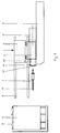
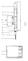
- Fig. 1
- eine Draufsicht auf eine erste Ausführung der erfindungsgemäßen spanabhebenden Werkzeugmaschine mit einem eingespannten Tieflochbohrer, der in einem Aufnahmelager mittels Bohrbuchsenhalter und Bohrbuchse zusätzlich geführt ist,
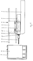
- Fig. 2
- die Werkzeugmaschine entsprechend Fig. 1 während des Tieflochbohrens,
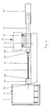
- Fig. 3
- eine Draufsicht auf die erfindungsgemäße Werkzeugmaschine nach Fig. 1 mit einzusetzendem Fräs-Werkzeug und zurückgefahrenem Schlitten, so daß das Aufnahmelager mit seiner freien Bohrung über die Spindelstocknase gefahren ist,
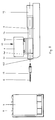
- Fig. 4
- eine Draufsicht der erfindungsgemäßen Werkzeugmaschine nach Fig. 1 mit eingespanntem Fräser,
- Fig. 5
- eine Werkzeugmaschine entsprechend Fig. 4 mit teilweise vorgefahrenem Turm,
- Fig. 6
- eine Draufsicht auf eine zweite Ausführung einer erfindungsgemäßen spanabhebenden Werkzeugmaschine mit einem eingespannten Tieflochbohrer, der zusätzlich in einem Aufnahmelager mittels Bohrbuchsenhalter und Bohrbuchse geführt ist,
- Fig. 7
- die Werkzeugmaschine entsprechend Fig. 6 während des Tieflochbohrens,
- Fig. 8
- eine Draufsicht auf die erfindungsgemäße Werkzeugmaschine nach Fig. 6 mit einzusetzendem Fräs-Werkzeug und zurückgefahrenem Schlitten, so daß das Aufnahmelager mit seiner freien Bohrung über das Endteil der Pinole gefahren ist,
- Fig. 9
- eine Draufsicht der Werkzeugmaschine nach Fig. 6 mit eingespanntem Fräser und
- Fig. 10
- eine Werkzeugmaschine entsprechend Fig. 9 mit teilweise vorgefahrener Pinole.
Claims (10)
- Spanabhebende Werkzeugmaschine zum mechanischen Bearbeiten von Werkstücken, durch Tieflochbohren, Fräsen, Bohren, Gewindeschneiden, Reiben od.dgl., umfassend eine über eine Spanneinrichtung ein Werkzeug (6,11,12) direkt und/oder indirekt aufnehmende, in einem Spindelstock (4, 14) gelagerte Spindel (42, 142) und ein Aufnahmelager (10) mit einer Bohrung für einen darin einsetzbaren Bohrbuchsenhalter mit Bohrbuchse (101) und/oder eine Späneschleuse (102), dadurch gekennzeichnet, daß das Aufnahmelager (10) parallel zum Bearbeitungsvorschub und mindestens teilweise über die Spanneinrichtung der Spindel (42, 142) verfahrbar ausgebildet ist derart, daß die Spanneinrichtung die Bohrung des Aufnahmelagers (10) mindestens teilweise durchtaucht.
- Werkzeugmaschine nach Anspruch 1, dadurch gekennzeichnet, daß das Aufnahmelager (10) mindestens teilweise über einen werkstückseitigen Endbereich (41, 141) des Spindelstocks (4, 14) verfahrbar ausgebildet ist.
- Werkzeugmaschine nach Anspruche 1 oder 2, , dadurch gekennzeichnet, daß das Aufnahmelager (10) im werkstückseitigen Endbereich eines parallel zum Bearbeitungsvorschub verfahrbar gelagerten Schlittens (7) angeordnet ist.
- Werkzeugmaschine nach einem der Ansprüche 1 bis 3, dadurch gekennzeichnet, daß der Spindelstock (4, 14) vertikal verfahrbar auf einem auf einem Maschinengestell angeordneten Turm (2) angeordnet ist.
- Werkzeugmaschine nach einem der Ansprüche 1 bis 4, dadurch gekennzeichnet, daß der Turm (2), den Bearbeitungsvorschub realisierend, in Richtung der Achse des Werkzeuges (6) verschiebbar mit dem Maschinengestell (3) wirkverbunden ist.
- Werkzeugmaschine nach Anspruch 5, dadurch gekennzeichnet, daß der Turm (2) als Portal ausgebildet ist, in dessen Mittenbereich der Spindelstock (4) mit dem Schlitten (7) vertikal verfahrbar angeordnet ist.
- Werkzeugmaschine nach einem der Ansprüche 1 bis 4, dadurch gekennzeichnet, daß der Spindelstock als in einem Pinolenstock (15) gelagerte Pinole (14) ausgebildet ist, wobei das werkstückseitige Endteil der Pinole (141) mindestens teilweise durch die Bohrung des Aufnahmelagers (10) hindurchtauchen kann.
- Werkzeugmaschine nach einem der Ansprüche 1 bis 7, dadurch gekennzeichnet, daß sie als Koordinaten-Tieflochbohrmaschine ausgebildet ist.
- Bohrbuchsenträgermittel zur Verwendung in einer einen Spindelstock (4, 14) und eine Spindel (42, 142) mit Spanneinrichtung umfassenden spanabhebenden Werkzeugmaschine, umfassend ein Aufnahmelager (10) zur Aufnahme eines Bohrbuchsenhalters mit Bohrbuchse (101) und/oder einer Späneschleuse (102) sowie einen Schlitten (7), wobei das Aufnahmelager (10) im Endbereich des Schlittens (7) angeordnet ist, dadurch gekennzeichnet, daß der Schlitten (7) derart an der Werkzeugmaschine anbringbar ist, daß das Aufnahmelager parallel zum Bearbeitungsvorschub über die Spanneinrichtung der Spindel (42, 142) hinweg verfahrbar ist, so daß die Spanneinrichtung das Aufnahmelager mindestens teilweise durchtaucht.
- Bohrbuchsenträgermittel nach Anspruch 9, dadurch gekennzeichnet, daß das Aufnahmelager eine Bohrung mit einem Durchmesser umfaßt, der größer als der Durchmesser des werkstückseitigen Endbereiches eines Spindelstocks (4, 14) ist.
Applications Claiming Priority (2)
| Application Number | Priority Date | Filing Date | Title |
|---|---|---|---|
| DE4425603 | 1994-07-06 | ||
| DE4425603A DE4425603A1 (de) | 1994-07-06 | 1994-07-06 | Tieflochbohrmaschine |
Publications (2)
| Publication Number | Publication Date |
|---|---|
| EP0699493A1 EP0699493A1 (de) | 1996-03-06 |
| EP0699493B1 true EP0699493B1 (de) | 1998-09-30 |
Family
ID=6523627
Family Applications (1)
| Application Number | Title | Priority Date | Filing Date |
|---|---|---|---|
| EP95250164A Expired - Lifetime EP0699493B1 (de) | 1994-07-06 | 1995-07-05 | Spanabhebende Werkzeugmaschine |
Country Status (4)
| Country | Link |
|---|---|
| EP (1) | EP0699493B1 (de) |
| AT (1) | ATE171658T1 (de) |
| DE (2) | DE4425603A1 (de) |
| ES (1) | ES2125555T3 (de) |
Families Citing this family (4)
| Publication number | Priority date | Publication date | Assignee | Title |
|---|---|---|---|---|
| CN1079308C (zh) * | 1999-03-24 | 2002-02-20 | 叶小宁 | 超长精密深孔的加工方法及工艺设备 |
| DE102009023519A1 (de) * | 2009-05-30 | 2010-12-02 | Samag Saalfelder Werkzeugmaschinen Gmbh | Werkzeugmaschine |
| CN101850520B (zh) * | 2010-03-10 | 2013-06-19 | 无锡桥联数控机床有限公司 | 一种深孔加工工装结构 |
| CN105834482A (zh) * | 2016-04-28 | 2016-08-10 | 齐齐哈尔精工伟业机床有限公司 | 滑台式深孔加工专用钻床 |
Family Cites Families (5)
| Publication number | Priority date | Publication date | Assignee | Title |
|---|---|---|---|---|
| DE2208508A1 (de) * | 1972-02-18 | 1973-08-23 | Wohlenberg Kg H | Waagerecht-tiefbohrmaschine |
| DE3600967C1 (de) * | 1986-01-15 | 1987-05-21 | Tiefbohrtechnik Gmbh Tbt | Tiefbohrmaschine |
| JPS62264813A (ja) * | 1986-05-09 | 1987-11-17 | Honda Motor Co Ltd | 深孔穿孔機 |
| DE9307756U1 (de) | 1993-05-21 | 1993-08-05 | Klukowski, Werner, 73104 Börtlingen | Vorrichtung zum Sichern der Türen von Fahrzeugen, insbesondere Wohnmobilen, Campingwagen und Kastenwagen gegen Einbruch |
| DE9307758U1 (de) * | 1993-05-22 | 1993-08-26 | Buck, Markus, 91622 Rügland | Tieflochbohrmaschine |
-
1994
- 1994-07-06 DE DE4425603A patent/DE4425603A1/de not_active Withdrawn
-
1995
- 1995-07-05 ES ES95250164T patent/ES2125555T3/es not_active Expired - Lifetime
- 1995-07-05 AT AT95250164T patent/ATE171658T1/de not_active IP Right Cessation
- 1995-07-05 EP EP95250164A patent/EP0699493B1/de not_active Expired - Lifetime
- 1995-07-05 DE DE59503769T patent/DE59503769D1/de not_active Expired - Fee Related
Also Published As
| Publication number | Publication date |
|---|---|
| EP0699493A1 (de) | 1996-03-06 |
| DE4425603A1 (de) | 1995-12-14 |
| ES2125555T3 (es) | 1999-03-01 |
| DE59503769D1 (de) | 1998-11-05 |
| ATE171658T1 (de) | 1998-10-15 |
Similar Documents
| Publication | Publication Date | Title |
|---|---|---|
| DE4040554C2 (de) | ||
| EP0999002B1 (de) | Drehmaschine mit Gegenspindel | |
| DE69207109T2 (de) | Werkzeugmaschine | |
| EP1409182B1 (de) | Werkzeugmaschine | |
| EP0229909B1 (de) | Tiefbohrmaschine | |
| DE4236866A1 (de) | Drehmaschine | |
| DE69012585T2 (de) | Drehautomat mit unbeweglichem spindelstock und aufbearbeitungsspindel. | |
| EP0301226B1 (de) | Werkzeug für tiefliegende Innenbearbeitung hohler Werkstücke | |
| EP2036638B1 (de) | Einrichtung zur Bearbeitung insbesondere großer Durchmesser eines Werkstücks | |
| DE4023453C1 (de) | ||
| DE2928876A1 (de) | Langdrehautomat | |
| DE10130760A1 (de) | Drehmaschine | |
| EP1074333B1 (de) | Drehmaschine mit zwei Werkzeugträgersystemen | |
| EP0699493A1 (de) | Spanabhebende Werkzeugmaschine | |
| DE4419610C2 (de) | CNC-Drehmaschine für schwere Zerspanung | |
| DE4330858C1 (de) | Verfahren zum Bearbeiten eines Werkstückes auf einem CNC-Drehautomaten sowie CNC-Drehautomat | |
| DE3412576C1 (de) | Fraes-Bohrvorrichtung | |
| DE4013327A1 (de) | Maschine zur spanenden metallbearbeitung | |
| DE102005039089A1 (de) | Drehmaschine | |
| DE10358681B4 (de) | Werkzeugmaschine zum Bearbeiten von wellenartigen Werkstücken | |
| DE102005053155A1 (de) | Verfahren zur Herstellung von Steuerbuchsen für kraftunterstützte Lenkungen und Steuerventil für eine kraftunterstützte Lenkung | |
| DE10104181A1 (de) | Drehmaschine | |
| DE153753C (de) | ||
| DE202009002616U1 (de) | Werkzeug zur Bearbeitung von Außen- und/oder Innendurchmessern von Werkstücken | |
| DD149176A2 (de) | Schwenkbare bohreinrichtung |
Legal Events
| Date | Code | Title | Description |
|---|---|---|---|
| PUAI | Public reference made under article 153(3) epc to a published international application that has entered the european phase |
Free format text: ORIGINAL CODE: 0009012 |
|
| AK | Designated contracting states |
Kind code of ref document: A1 Designated state(s): AT CH DE ES FR GB IT LI |
|
| 17P | Request for examination filed |
Effective date: 19960530 |
|
| 17Q | First examination report despatched |
Effective date: 19960723 |
|
| GRAG | Despatch of communication of intention to grant |
Free format text: ORIGINAL CODE: EPIDOS AGRA |
|
| GRAG | Despatch of communication of intention to grant |
Free format text: ORIGINAL CODE: EPIDOS AGRA |
|
| GRAH | Despatch of communication of intention to grant a patent |
Free format text: ORIGINAL CODE: EPIDOS IGRA |
|
| GRAH | Despatch of communication of intention to grant a patent |
Free format text: ORIGINAL CODE: EPIDOS IGRA |
|
| GRAA | (expected) grant |
Free format text: ORIGINAL CODE: 0009210 |
|
| AK | Designated contracting states |
Kind code of ref document: B1 Designated state(s): AT CH DE ES FR GB IT LI |
|
| REF | Corresponds to: |
Ref document number: 171658 Country of ref document: AT Date of ref document: 19981015 Kind code of ref document: T |
|
| REG | Reference to a national code |
Ref country code: CH Ref legal event code: EP |
|
| REF | Corresponds to: |
Ref document number: 59503769 Country of ref document: DE Date of ref document: 19981105 |
|
| GBT | Gb: translation of ep patent filed (gb section 77(6)(a)/1977) |
Effective date: 19990104 |
|
| REG | Reference to a national code |
Ref country code: CH Ref legal event code: NV Representative=s name: E. BLUM & CO. PATENTANWAELTE |
|
| ET | Fr: translation filed | ||
| REG | Reference to a national code |
Ref country code: ES Ref legal event code: FG2A Ref document number: 2125555 Country of ref document: ES Kind code of ref document: T3 |
|
| PLBE | No opposition filed within time limit |
Free format text: ORIGINAL CODE: 0009261 |
|
| STAA | Information on the status of an ep patent application or granted ep patent |
Free format text: STATUS: NO OPPOSITION FILED WITHIN TIME LIMIT |
|
| 26N | No opposition filed | ||
| PGFP | Annual fee paid to national office [announced via postgrant information from national office to epo] |
Ref country code: CH Payment date: 20000710 Year of fee payment: 6 |
|
| PGFP | Annual fee paid to national office [announced via postgrant information from national office to epo] |
Ref country code: AT Payment date: 20000714 Year of fee payment: 6 |
|
| PGFP | Annual fee paid to national office [announced via postgrant information from national office to epo] |
Ref country code: GB Payment date: 20010627 Year of fee payment: 7 |
|
| PG25 | Lapsed in a contracting state [announced via postgrant information from national office to epo] |
Ref country code: AT Free format text: LAPSE BECAUSE OF NON-PAYMENT OF DUE FEES Effective date: 20010705 |
|
| PGFP | Annual fee paid to national office [announced via postgrant information from national office to epo] |
Ref country code: ES Payment date: 20010706 Year of fee payment: 7 |
|
| PGFP | Annual fee paid to national office [announced via postgrant information from national office to epo] |
Ref country code: FR Payment date: 20010717 Year of fee payment: 7 |
|
| PG25 | Lapsed in a contracting state [announced via postgrant information from national office to epo] |
Ref country code: LI Free format text: LAPSE BECAUSE OF NON-PAYMENT OF DUE FEES Effective date: 20010731 Ref country code: CH Free format text: LAPSE BECAUSE OF NON-PAYMENT OF DUE FEES Effective date: 20010731 |
|
| REG | Reference to a national code |
Ref country code: GB Ref legal event code: IF02 |
|
| REG | Reference to a national code |
Ref country code: CH Ref legal event code: PL |
|
| PG25 | Lapsed in a contracting state [announced via postgrant information from national office to epo] |
Ref country code: GB Free format text: LAPSE BECAUSE OF NON-PAYMENT OF DUE FEES Effective date: 20020705 |
|
| PG25 | Lapsed in a contracting state [announced via postgrant information from national office to epo] |
Ref country code: ES Free format text: LAPSE BECAUSE OF NON-PAYMENT OF DUE FEES Effective date: 20020706 |
|
| PGFP | Annual fee paid to national office [announced via postgrant information from national office to epo] |
Ref country code: DE Payment date: 20020731 Year of fee payment: 8 |
|
| GBPC | Gb: european patent ceased through non-payment of renewal fee |
Effective date: 20020705 |
|
| PG25 | Lapsed in a contracting state [announced via postgrant information from national office to epo] |
Ref country code: FR Free format text: LAPSE BECAUSE OF NON-PAYMENT OF DUE FEES Effective date: 20030331 |
|
| REG | Reference to a national code |
Ref country code: FR Ref legal event code: ST |
|
| PG25 | Lapsed in a contracting state [announced via postgrant information from national office to epo] |
Ref country code: DE Free format text: LAPSE BECAUSE OF NON-PAYMENT OF DUE FEES Effective date: 20040203 |
|
| REG | Reference to a national code |
Ref country code: ES Ref legal event code: FD2A Effective date: 20030811 |
|
| PG25 | Lapsed in a contracting state [announced via postgrant information from national office to epo] |
Ref country code: IT Free format text: LAPSE BECAUSE OF NON-PAYMENT OF DUE FEES Effective date: 20050705 |