EP0699507B1 - Serre joint avec vis inclinée - Google Patents
Serre joint avec vis inclinée Download PDFInfo
- Publication number
- EP0699507B1 EP0699507B1 EP95101180A EP95101180A EP0699507B1 EP 0699507 B1 EP0699507 B1 EP 0699507B1 EP 95101180 A EP95101180 A EP 95101180A EP 95101180 A EP95101180 A EP 95101180A EP 0699507 B1 EP0699507 B1 EP 0699507B1
- Authority
- EP
- European Patent Office
- Prior art keywords
- screw
- bar
- clamp
- jaw
- axis
- Prior art date
- Legal status (The legal status is an assumption and is not a legal conclusion. Google has not performed a legal analysis and makes no representation as to the accuracy of the status listed.)
- Expired - Lifetime
Links
Images


Classifications
-
- B—PERFORMING OPERATIONS; TRANSPORTING
- B25—HAND TOOLS; PORTABLE POWER-DRIVEN TOOLS; MANIPULATORS
- B25B—TOOLS OR BENCH DEVICES NOT OTHERWISE PROVIDED FOR, FOR FASTENING, CONNECTING, DISENGAGING OR HOLDING
- B25B5/00—Clamps
- B25B5/06—Arrangements for positively actuating jaws
- B25B5/068—Arrangements for positively actuating jaws with at least one jaw sliding along a bar
-
- B—PERFORMING OPERATIONS; TRANSPORTING
- B25—HAND TOOLS; PORTABLE POWER-DRIVEN TOOLS; MANIPULATORS
- B25B—TOOLS OR BENCH DEVICES NOT OTHERWISE PROVIDED FOR, FOR FASTENING, CONNECTING, DISENGAGING OR HOLDING
- B25B5/00—Clamps
- B25B5/06—Arrangements for positively actuating jaws
- B25B5/10—Arrangements for positively actuating jaws using screws
- B25B5/102—Arrangements for positively actuating jaws using screws with at least one jaw sliding along a bar
Definitions
- This invention relates to a clamp as defined in the preamble of claim 1.
- a clamp of this type is disclosed in DE-A 2 539 613.
- the known clamp includes a clamp body having a screw receiving opening and a bar receiving opening which are parallel to each other. No retaining means are provided and the complete clamp body has to be tilted with respect to the bar for providing sufficient resistance against the clamping forces exerted by the screw onto the work piece.
- the clamping end of the screw is received in a slot provided in the jaw.
- the jaw end of the screw engages the jaw at the free end thereof, i.e. at the end opposite to the bar engaging end of the jaw.
- a clamp comprising the features of claim 1.
- the clamp includes a bar defining a bar axis.
- a clamp body is movable along the bar axis, and a retainer is movably mounted in the clamp body to engage the bar selectively and thereby to hold the clamp body selectively against movement with respect to the bar in at least a first direction along the bar axis.
- a screw is mounted in the clamp body, and the screw comprises a jaw engaging portion, an actuator engaging portion, and a screw axis extending therebetween.
- a jaw is mounted to the jaw engaging portion of the screw such that movement of the screw with respect to the clamp body along the screw axis causes the jaw to translate with respect to the clamp body along the bar axis.
- An actuator is coupled to the actuator engaging portion of the screw for rotation about the screw axis such that rotation of the actuator shifts the screw with respect to the clamp body.
- a workpiece supporting element is mounted to the bar to oppose the jaw, and the actuator is positioned alongside the bar for at least some positions of the clamp body along the bar axis.
- the screw opening of the clamp body is tilted with respect to the bar opening such that the actuator engaging portion of the screw at the actuator is farther from the bar than is the jaw engaging portion, thereby providing increased clearance between the actuator and the bar.
- this invention can be used in a variety of bar clamps including pipe clamps, and in all cases clearance between the actuator and the bar is increased as compared with a conventional clamp of the type having a screw axis parallel to the bar axis.
- the actuator can take many forms, including handles that are pivotably mounted to the screw, handles that are rigidly mounted to the screw, and threaded collars that rotate with respect to the screw in use.
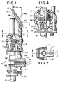
- Figure 1 is a side view of a pipe clamp that incorporates a first preferred embodiment of this invention.
- Figure 2 is a cross-sectional view taken along line 2-2 of Figure 1.
- Figure 3 is a side view at an enlarged scale of a portion of the clamp of Figure 1.
- Figure 4 is another side view of a portion of the clamp of Figure 1 showing the retainers positioned to disengage the pipe.
- Figure 5 is a cross-sectional view taken along line 5-5 of Figure 3.
- Figure 6 is a side view taken along line 6-6 of Figure 3.
- Figure 7 is a side view of a second preferred embodiment of this invention.
- Figure 8 is a side view of a third preferred embodiment of this invention.
- FIG. 1 shows an overall view of a clamp 10 which incorporates a first preferred embodiment of this invention.
- the clamp 10 includes a bar 12 which in this embodiment is a pipe such as a length of three-quarter inch (1,9 cm) black pipe having an outside diameter of about 1 inch (2,54 cm). Of course, other sizes of pipe and other types of bars can be substituted for the illustrated pipe.
- the pipe 12 defines a bar axis 14.
- FIG. 1 Three components are slideably mounted on the pipe 12: a clamp body 16, a jaw 48, and a workpiece engaging element 64.
- Figures 2-6 provide more detailed views of the clamp body 16 on the pipe 12.
- the clamp body 16 defines a threaded opening 18, which in turn defines a jaw end 20 and a handle end 22.
- the clamp body 16 also defines an unthreaded opening 24 which receives the pipe 12.
- At least one retainer 26 is mounted in the clamp body 16 in alignment with the unthreaded opening 24 so as to engage the pipe 12.
- the preferred embodiment uses four parallel retainers 26, each defining a central opening 28 through which the pipe 12 passes.
- the retainers 26 are biased by a spring 30 to an inclined position as shown in Figure 3 in which the retainers 26 positively engage the pipe 12 so as to prevent movement of the pipe 12 downwardly as shown in Figure 3 with respect to the clamp body 16.
- the retainers 26 can be released from the pipe 12 by means of a release element 32 which is pivotably mounted to the clamp body 16 at a pivot axis 34.
- the release element 32 is generally U-shaped in configuration, and it defines recesses 36 that engage the retainers 26 on both sides of the pipe 12.
- Figure 3 shows the release element 32 in its normal or rest position.
- a user can rotate the release element 32 about the pivot axis 34 (in a counter-clockwise direction in the view of Figure 4) so as to move the retainers 26 to a release position, in which the retainers 26 are more nearly perpendicular to the bar axis 14.
- the retainers 26 release the pipe 12, thereby allowing the user to move the clamp body 16 in either direction as desired along the length of the pipe 12.
- the spring 30 restores the retainers 26 to the inclined position of Figure 3.
- the retainers 26 are conventional in the art, and their use and construction are well known to those skilled in the art.
- a threaded screw 38 is rotatably mounted in the threaded opening 18 so as to protrude out of both sides of the opening 18.
- the screw 38 defines a jaw engaging portion 40 which includes a circumferential recess 42.
- the screw 38 also includes an actuator engaging portion 44 which in this embodiment is flattened and defines an opening for a pivot joint.
- the screw 38 is rectilinear, and the centerline of the screw 38 forms a screw axis 46 ( Figure 1).
- the screw axis 46 is inclined with respect to the bar axis 14 such that the jaw engaging portion 40 of the screw 38 is closer to the pipe 12 than is the actuator engaging portion 44. Similarly, the jaw end 20 of the threaded opening 18 is closer to the pipe 12 than is the handle end 22.
- a jaw 48 is slideably mounted on the pipe 12.
- the jaw 48 defines an opening 50 that slidingly receives the pipe 12.
- the jaw 48 also defines a slot 52 that receives the jaw engaging portion 40 of the screw 38.
- a ridge 54 on the jaw 48 fits into the circumferential recess 42 of the screw 38.
- the slot 52 is angled with respect to both the bar axis 14 and the screw axis 46, and the jaw engaging portion 40 is free both to rotate about the screw axis 46 with respect to the jaw 48, and to translate along the slot 52.
- the slot is substantially perpendicular to the bar axis 14.
- a resilient pad 56 is removably mounted on the jaw 48 to engage a workpiece (not shown).
- An actuator such as the illustrated handle 58 is mounted on the actuator engaging portion 44 of the screw 38.
- the actuator 58 is secured to the screw 38 at a pivot joint 50.
- the actuator 58 defines a free end 62 ( Figure 1) which can be placed on the screw axis 46 when it is desired to rotate the screw 38 rapidly.
- the actuator 58 can be pivoted to a transverse position as shown in Figure 1 when it is desired to apply substantial torque to the screw 38 in order to develop clamping forces.
- the workpiece engaging element 64 also defines an opening 66 that receives the pipe 12.
- the workpiece engaging element 64 includes a pad 68 for contacting a workpiece W.
- Retainers 70 are mounted in the workpiece engaging element 64 to releasably hold the workpiece engaging element 64 from moving away from the clamp body 16.
- the clamp body 16 and the workpiece engaging element 64 are positioned appropriately on the pipe 12 to bring the pads 56, 68 closely adjacent to the workpiece W.
- the handle 58 is then aligned with the screw axis 46 and rotated to develop a slight clamping pressure of the pads 56, 68 against a workpiece W.
- the handle 58 is moved to the transverse position shown in dotted lines in Figure 1 and torques are applied via the handle 58 to the screw 38 in order to develop the desired clamping pressure.
- the jaw engaging portion of the screw 38 moves along the slot 52 so as more closely to approach the pipe 12.
- the retainers 26, 70 engage the pipe 12 to prevent the clamp body 16 and the workpiece engaging element 64, respectively, from moving away from one another along the pipe 12 in response to the clamping forces.
- the included angle ⁇ between the bar axis 14 and the screw axis 46 is about 3°. This inclining of the screw axis 46 increases the clearance between the handle 58 and the pipe 12, and thereby facilitates operation of the clamp 10.
- this included angle can be increased or decreased as desired from the 3° angle illustrated. In many applications it will be advantageous to have the included angle less than 5°.
- the arrangement described above provides the further advantage that the jaw engaging portion 40 engages the jaw 48 at a point closer to the pipe 12 than would otherwise be the case. With this arrangement, it is possible to develop clamping forces closer to the pipe 12, which is important for many clamping applications. In addition, by positioning the screw 38 as discussed above, there is less of a tendency for the screw 38 to tilt the jaw 48 with respect to the pipe 12, particularly when clamping narrow workpieces.
- the clearance-increasing function of the arrangement discussed above is particularly important in a class of bar clamps such as pipe clamps where the separation between the screw and the clamp is less than 1 inch (2,54 cm).
- the separation between the pipe and the screw is preferably less than 1 inch (2,54 cm), more preferably less than 3/4 inch (1,9 cm) and most preferably no more than about 1/2 inch (1,27 cm).
- clearance between the handle and the pipe is severely limited, and the inclined screw described above provides the important advantage of increasing handle clearance.
- Figure 1 shows the clamp 10 arranged to apply a compressive load to a workpiece W.
- the clamp body 16 and the workpiece engaging element 64 can be rearranged on the pipe such that the pads 56, 68 oppose one another facing outwardly rather than facing toward one another as in Figure 1.
- the clamp body 16, the workpiece engaging element 64, the jaw 48 and the handle 58 can be injection molded from a suitable material such as a 30% glass-reinforced nylon.
- the pads 56, 68 can be injected molded of an elastomeric material such as the resin sold by Monsanto under the trade name SANTOPRENE.
- the retainers 26, 70 can be formed from plate metal such as 1051 M steel having a hardness such as RC-50.
- the screw 38 can be formed of a material such as 1031 steel.
- FIG 7 shows a clamp 10' which incorporates a second preferred embodiment of this invention.
- the clamp 10' is substantially similar to the clamp 10, and the following discussion will focus only on the differences.
- a key difference is that the clamp body 16' defines a threaded opening 18' that is tilted with respect to the bar axis 14' by an included angle of about 15°.
- the screw 38' is connected to the jaw 48' by a ball joint as shown, and the actuator or handle 58' is fixed to the screw 38'.
- the relatively larger included angle between the screw 38' and the pipe 12' allows a large fixed handle 58' to be used.
- the workpiece engaging element 64' can be identical to that shown in Figure 1 above.
- FIG 8 shows a clamp 10'' which incorporates a third preferred embodiment of this invention.
- the clamp body 16'' defines an opening 18'' which is oriented at a 15° angle with respect to the pipe 12''. In this case the opening is not threaded, and a slot 19'' is defined by the clamp body 16'', extending along a diameter of the opening 18''.
- the opening 18'' is sized to receive the screw 38'' for sliding movement, without any threaded connection between the screw 38'' and the clamp body 16''.
- a pin 47'' is fixed to the screw 38'' to slide in the slot 19''. In this way, the screw 38'' is prevented from rotating with respect to the clamp body 16''.
- the actuator 58'' is formed as a rotating collar having a threaded opening that receives the screw 38''. Wrench openings 59'' are provided around the circumference of the actuator 58'' to assist the user in applying large torques to the actuator 58''.
- the included angle between the screw 38'' and the pipe 12'' is in this embodiment 15°, though other angles greater than about 10° are suitable.
- the actuator 58'' is rotated in order to advance and retract the screw 38'' with respect to the clamp body 16''.
- the inclined screw 38'' allows a larger diameter actuator 58'' to be used, once again improving handle clearance.
Landscapes
- Engineering & Computer Science (AREA)
- Mechanical Engineering (AREA)
- Gripping Jigs, Holding Jigs, And Positioning Jigs (AREA)
- Jigs For Machine Tools (AREA)
- Clamps And Clips (AREA)
- Dental Tools And Instruments Or Auxiliary Dental Instruments (AREA)
- Supports For Pipes And Cables (AREA)
- Load-Engaging Elements For Cranes (AREA)
- Processing And Handling Of Plastics And Other Materials For Molding In General (AREA)
Claims (17)
- Serre-joint (10, 10', 10'') comprenant :une barre (12, 12', 12'') définissant un axe de barre (14, 14') ;un corps de serrage (16, 16', 16'') mobile suivant l'axe de barre (14, 14'), ledit corps de serrage (16, 16', 16'') comprenant une ouverture pour vis (18, 18', 18'') ayant une extremité côté mors (20) et une extrémité côté actionneur (22), et une ouverture pour barre (24) servant à recevoir la barre pour un mouvement guidé suivant l'axe de barre (14, 14') ;une vis (38, 38', 38'') montée dans l'ouverture pour vis (18, 18', 18'') pour s'étendre vers l'extérieur à partir de l'extrémité côté mors (20), ladite vis comprenant une partie engagement de mors (40), une partie engagement d'actionneur (44) et un axe de vis (46) s'étendant entre elles ;un mors (48, 48'), monté sur la partie engagement de mors (40) de la vis (38, 38', 38'') au moyen d'une fente (52), de telle manière que le mouvement de la vis par rapport au corps de serrage, suivant l'axe de la vis, provoque la translation du mors par rapport à la barre et du corps de serrage suivant l'axe de la barre, ledit mors (48, 48') définissant une ouverture (50) destinée à recevoir la barre (12, 12', 12'') et à guider ledit mors (48, 48') pour un déplacement suivant ledit axe de barre (14, 14') ;un actionneur (58, 58', 58''), relié à la partie engagement d'actionneur (44) pour une rotation autour de l'axe de vis (46), de telle manière que la rotation de l'actionneur déplace la vis (38, 38', 38'') par rapport au corps de serrage (16, 16', 16'') ; etun élément de support (64, 64') pour la pièce à traiter, monté sur la barre (12, 12', 12'') de façon à faire face au mors (48, 48') ;dans lequel l'actionneur (58, 58', 58'') est positionné le long de la barre (12, 12', 12'') pour au moins quelques positions du corps de serrage (16, 16', 16'') suivant l'axe de barre (14, 14') ;
caractérisé en ce queun élément de retenue (26) est monté de manière mobile dans le corps de serrage (16, 16', 16'') afin de venir sélectivement en prise avec la barre (12, 12', 12'') et d'empêcher ainsi tout mouvement du corps de serrage (16, 16', 16'') sélectivement par rapport à la barre dans au moins un premier sens suivant l'axe de la barre ;ladite ouverture pour vis (18, 18', 18'') est inclinée par rapport à l'ouverture pour barre (24), de telle manière que l'extrémité côté mors (20) soit plus proche de l'ouverture pour barre (24) que ne l'est l'extrémité côté actionneur (22) ;ladite partie engagement de mors (40) est logée, de manière à coulisser, dans la fente (52) afin qu'un mouvement de la vis (38, 38', 38'') par rapport au corps de serrage (16, 16', 16''), suivant l'axe de vis (46), provoque un coulissement de la partie engagement de mors (40) dans ladite fente (52) en direction ou en s'éloignant de ladite barre (12, 12', 12'') ; etdans lequel l'axe de vis (46) est incliné par rapport à l'axe de barre (14, 14'), de telle manière que la partie engagement d'actionneur (44) de la vis, au niveau de l'actionneur (58, 58', 58''), soit plus éloignée de la barre que ne l'est la partie engagement de mors (40), pour ainsi constituer un plus grand espace entre l'actionneur et la barre, et de telle manière que ladite partie engagement de mors (40) soit suffisamment proche de ladite barre (12, 12', 12'') pour réduire la tendance de la vis (38, 38', 38'') à incliner le mors (48, 48') par rapport à la barre (12, 12', 12''). - Serre-joint selon la revendication 1, dans lequel le mors (48, 48') et l'élément de support de pièce (64, 64') sont orientés de manière à comprimer entre eux une pièce à traiter.
- Serre-joint selon la revendication 1, dans lequel le mors (48, 48') et l'élément de support de pièce (64, 64') sont orientés de manière à écarter une pièce.
- Serre-joint selon l'une quelconque des revendications 1 à 3, dans lequel la barre (12, 12', 12'') comprend un tube.
- Serre-joint selon l'une quelconque des revendications 1 à 4, dans lequel l'axe de vis (46) et l'axe de barre (14, 14') définissent un angle aiqu qui est plus petit que 5°.
- Serre-joint selon l'une quelconque des revendications 1 à 4, dans lequel l'axe de vis (46) et l'axe de barre (14, 14') définissent un angle aiqu qui est plus grand que 5°.
- Serre-joint selon l'une quelconque des revendications 1 à 6, dans lequel la fente (52) est définie dans ledit mors (48, 48') et forme un angle par rapport à la fois à l'axe de vis (46) et à l'axe de barre (14, 14').
- Serre-joint selon l'une quelconque des revendications 1 à 7, dans lequel le mors (48, 48') comprend une crête (54) adjacente à la fente (52), et dans lequel la vis (38, 38', 38'') définit une cavité circonférentielle (42) destinée à recevoir la crête afin de relier la vis au mors tout en autorisant la rotation de la vis et le mouvement de la vis le long de la crête.
- Serre-joint selon l'une quelconque des revendications 1 à 8, dans lequel la séparation entre ladite barre (12, 12', 12'') et ladite vis (38, 38', 38'') pour réduire la tendance de la vis à incliner le mors (48, 48'), est inférieure à 1 pouce (2,54 cm).
- Serre-joint selon l'une quelconque des revendications 1 à 9, dans lequel ledit élément de retenue (26) est mobile vers une position de libération, dans laquelle l'élément de retenue (26) autorise un mouvement du corps de serrage (16, 16', 16'') dans le premier sens par rapport à la barre (12, 12', 12'').
- Serre-joint selon l'une quelconque des revendications 1 à 10, dans lequel ladite ouverture pour barre (24) dudit corps de serrage (16, 16') n'est pas taraudée, ledit élément de retenue (26) étant placé autour du tube.
- Serre-joint selon l'une quelconque des revendications 1 à 11, dans lequel ladite ouverture (50) servant à guider ledit mors (48, 48') entoure ladite barre (12, 12').
- Serre-joint selon l'une quelconque des revendications 1 à 12, dans lequel l'ouverture pour vis (18, 18') est taraudée.
- Serre-joint selon la revendication 13, dans lequel l'actionneur comprend une manette (58, 58') fixée à la vis afin de tourner en même temps que la vis (38, 38').
- Serre-joint selon la revendication 1, dans lequel la manette (58) est montée, de manière à pouvoir pivoter, sur l'extrémité côté actionneur (44) de la vis (38) et est positionnée le long du tube (12) pour au moins quelques positions du corps de serrage (16) suivant le tube.
- Serre-joint selon l'une quelconque des revendications 1 à 12, dans lequel l'actionneur (58'') définit une ouverture taraudée qui reçoit la vis (38''), et dans lequel l'actionneur (58'') est monté, de façon à pouvoir tourner, sur le corps de serrage (16''), de telle manière qu'une rotation de l'actionneur par rapport au corps de serrage déplace la vis suivant l'axe de vis par rapport au corps de serrage.
- Serre-joint selon la revendication 16, dans lequel l'ouverture pour vis (18'') n'est pas taraudée.
Applications Claiming Priority (2)
| Application Number | Priority Date | Filing Date | Title |
|---|---|---|---|
| US28144894A | 1994-07-27 | 1994-07-27 | |
| US281448 | 1999-03-30 |
Publications (2)
| Publication Number | Publication Date |
|---|---|
| EP0699507A1 EP0699507A1 (fr) | 1996-03-06 |
| EP0699507B1 true EP0699507B1 (fr) | 1998-09-16 |
Family
ID=23077348
Family Applications (1)
| Application Number | Title | Priority Date | Filing Date |
|---|---|---|---|
| EP95101180A Expired - Lifetime EP0699507B1 (fr) | 1994-07-27 | 1995-01-27 | Serre joint avec vis inclinée |
Country Status (13)
| Country | Link |
|---|---|
| US (1) | US5775680A (fr) |
| EP (1) | EP0699507B1 (fr) |
| JP (1) | JP3018011B2 (fr) |
| CN (1) | CN1047338C (fr) |
| AT (1) | ATE171095T1 (fr) |
| AU (1) | AU678059B2 (fr) |
| BR (1) | BR9500422A (fr) |
| CA (1) | CA2134250C (fr) |
| DE (1) | DE69504791T2 (fr) |
| DK (1) | DK0699507T3 (fr) |
| ES (1) | ES2120641T3 (fr) |
| NZ (1) | NZ264778A (fr) |
| TW (1) | TW267124B (fr) |
Cited By (1)
| Publication number | Priority date | Publication date | Assignee | Title |
|---|---|---|---|---|
| DE102021132076A1 (de) | 2021-12-06 | 2023-06-07 | Ditabis Digital Biomedical Imaging Systems Ag | Spannvorrichtung |
Families Citing this family (31)
| Publication number | Priority date | Publication date | Assignee | Title |
|---|---|---|---|---|
| US6412767B1 (en) | 1998-03-06 | 2002-07-02 | American Tool Companies, Inc. | Clamping jaw |
| US6367787B1 (en) | 1999-03-01 | 2002-04-09 | American Tool Companies, Inc. | Hand clamp |
| GB2375985A (en) * | 2001-05-30 | 2002-12-04 | David Stockton | A modular bar clamp |
| GB2393414A (en) | 2001-08-10 | 2004-03-31 | American Tool Comp Inc | Increased and variable force and multi-speed clamps |
| NZ514441A (en) * | 2001-09-27 | 2004-02-27 | Cleco New Zealand Ltd | Clamp to suspend child's swing beneath doorway architrave |
| US6957808B2 (en) | 2001-11-13 | 2005-10-25 | Wmh Tool Group, Inc. | Apparatus for securing a workpiece |
| USD500238S1 (en) | 2002-02-01 | 2004-12-28 | Wmh Tool Group, Inc. | Apparatus for securing a work piece |
| USD488044S1 (en) | 2002-02-01 | 2004-04-06 | Wmh Tool Group, Inc. | Apparatus for securing a work piece |
| USD487864S1 (en) | 2002-02-01 | 2004-03-30 | Wmh Tool Group, Inc. | Base for an apparatus for securing a work piece |
| USD487220S1 (en) | 2003-01-21 | 2004-03-02 | Wmh Tool Group, Inc. | Base for an apparatus for securing a workpiece |
| US7066457B2 (en) * | 2003-01-21 | 2006-06-27 | Wmh Tool Group, Inc. | Apparatus for securing a workpiece |
| USD494828S1 (en) | 2003-01-21 | 2004-08-24 | Wmh Tool Group, Inc. | Apparatus for securing a workpiece |
| ATE483554T1 (de) * | 2003-08-01 | 2010-10-15 | Irwin Ind Tools Gmbh | Werkzeug zum erzeugen einer spannkraft und/oder einer spreizkraft |
| ES2246659B1 (es) * | 2003-09-22 | 2007-05-01 | Comercial De Maquinaria Alzira, S.L. | Abrazadera perfeccionada para maquinas. |
| US7159859B2 (en) * | 2003-10-03 | 2007-01-09 | Irwin Industrial Tool Company | Pipe clamp with releasable clamp body |
| WO2005056240A2 (fr) * | 2003-12-12 | 2005-06-23 | Irwin Industrial Tools Gmbh | Outil de serrage et/ou d'ecartement |
| US7798478B2 (en) * | 2004-02-23 | 2010-09-21 | Walter Meier (Manufacturing) Inc. | Parallel clamp and accessories therefor |
| DE102004024862A1 (de) * | 2004-05-19 | 2006-01-05 | Irwin Industrial Tools Gmbh | Spann- und/oder Spreizwerkzeug |
| US7604224B2 (en) * | 2005-09-28 | 2009-10-20 | The Stanley Works | Motorized clamp |
| US20070222130A1 (en) * | 2006-03-23 | 2007-09-27 | Rockler Companies Incorporated | Quick release mechanism |
| US7784774B2 (en) * | 2006-04-19 | 2010-08-31 | Irwin Industrial Tool Company | Assembly method and apparatus |
| USD607706S1 (en) | 2008-08-21 | 2010-01-12 | Keith Jastrow | Clamp |
| US8083555B2 (en) * | 2009-06-02 | 2011-12-27 | Hopkins Manufacturing Corporation | Jumper cable clamp |
| US9751193B2 (en) | 2013-03-15 | 2017-09-05 | Milwaukee Electric Tool Corporation | Clamping and spreading tool |
| US8888084B1 (en) * | 2014-04-02 | 2014-11-18 | Robert L. Aldredge | Saw horse pipe clamp |
| USD771456S1 (en) | 2014-08-01 | 2016-11-15 | Milwaukee Electric Tool Corporation | Pliers with control key |
| US20160207175A1 (en) | 2015-01-15 | 2016-07-21 | Milwaukee Electric Tool Corporation | Locking pliers with improved adjustment member |
| USD782891S1 (en) | 2015-04-02 | 2017-04-04 | Milwaukee Electric Tool Corporation | Locking pliers |
| DE102017113996A1 (de) * | 2017-06-23 | 2018-12-27 | Bessey Tool Gmbh & Co. Kg | Zwinge und Verfahren zum Betreiben einer Zwinge |
| US10279455B1 (en) | 2017-07-25 | 2019-05-07 | Royce D. Cooper | Pipe clamp |
| TWI796207B (zh) * | 2022-04-20 | 2023-03-11 | 美方總成國際有限公司 | 螺絲定位輔助器 |
Family Cites Families (28)
| Publication number | Priority date | Publication date | Assignee | Title |
|---|---|---|---|---|
| US927067A (en) | 1908-04-22 | 1909-07-06 | Abner W Offineer | Woodworker's clamp. |
| US1336755A (en) * | 1915-08-06 | 1920-04-13 | Parmelee Roy | Vise |
| US1241215A (en) * | 1916-01-26 | 1917-09-25 | Louis Hoffman | Extension-clamp. |
| US1340092A (en) * | 1919-12-22 | 1920-05-11 | Jr Adolf Tuscher | Pipe-wrench |
| US1783713A (en) * | 1927-08-22 | 1930-12-02 | Adjustable Clamp Co | Adjustable clamp |
| US1811518A (en) * | 1929-09-28 | 1931-06-23 | George E Palmer | Clamp |
| US2133892A (en) * | 1937-08-09 | 1938-10-18 | Gelinski Paul | C-clamp type hand tool |
| FR1019277A (fr) * | 1950-04-04 | 1953-01-20 | Perfectionnement aux engins de serrage tels que serre-joints, étaux et analogues | |
| US2815778A (en) * | 1954-02-23 | 1957-12-10 | Adjustable Clamp Co | Straight beam adjustable jaw clamp |
| US2815053A (en) * | 1954-08-20 | 1957-12-03 | Walker Dunaway Hundley | Straight beam clamp with angularly adjustable clamping surfaces |
| US3173674A (en) * | 1962-03-23 | 1965-03-16 | Wilf S Day & Night Service | Universal compression safety clamp |
| US3499206A (en) * | 1967-07-17 | 1970-03-10 | David E Quernheim | Attachment for bar clamp |
| DE2539613A1 (de) * | 1975-09-05 | 1977-03-10 | Bessey & Sohn | Spannvorrichtung zum festspannen von werkstuecken |
| US4042264A (en) * | 1976-01-12 | 1977-08-16 | Shumer James E | Clamping apparatus |
| US4083548A (en) * | 1976-11-11 | 1978-04-11 | Hackbarth Dale J | Adjustable clamp |
| US4132397A (en) * | 1977-08-22 | 1979-01-02 | Emerson Ward | Mounting bracket for a pipe clamp |
| US4339113A (en) * | 1979-07-25 | 1982-07-13 | Vosper George W | Screw operated jack |
| US4306710A (en) * | 1980-08-28 | 1981-12-22 | Vosper George W | Bar type jack having jaw extensions removably attached thereto |
| USD286369S (en) | 1983-06-06 | 1986-10-28 | Hahn Manufacturing Co. | Clamp |
| DE3347232A1 (de) * | 1983-12-28 | 1985-07-11 | Arthur Rinke & Söhne, Werkzeugfabrik, vorm. Langensiepen, GmbH & Co, 5630 Remscheid | Schraubzwinge |
| DE3700951A1 (de) * | 1987-01-15 | 1988-07-28 | Bessey & Sohn | Spannzwinge mit verstellbaren spanngliedern |
| DE8705546U1 (de) * | 1987-04-14 | 1987-05-27 | HERBA Werkzeugfabrik Max Herbstrith GmbH & Co KG, 5630 Remscheid | Schraubzwinge |
| US4989847A (en) * | 1989-09-12 | 1991-02-05 | Grant Chapman | Clamping device |
| US5096170A (en) * | 1990-08-23 | 1992-03-17 | Albin Stephen D | Clamp for picture frame tool and other purposes |
| US5197360A (en) * | 1992-02-28 | 1993-03-30 | Adjustable Clamp Co. | Adjustable clamp |
| USD346942S (en) | 1993-03-15 | 1994-05-17 | Btm Corporation | Plastic clamp |
| USD355104S (en) | 1994-01-06 | 1995-02-07 | Petersen Manufacturing Co., Inc. | Pipe clamp |
| USD365263S (en) | 1994-06-27 | 1995-12-19 | Sorensen Joseph A | Pipe clamp |
-
1994
- 1994-08-12 TW TW083107374A patent/TW267124B/zh active
- 1994-10-25 CA CA002134250A patent/CA2134250C/fr not_active Expired - Fee Related
- 1994-10-26 NZ NZ264778A patent/NZ264778A/en unknown
- 1994-11-02 AU AU77584/94A patent/AU678059B2/en not_active Ceased
- 1994-11-18 CN CN94118917A patent/CN1047338C/zh not_active Expired - Fee Related
-
1995
- 1995-01-27 AT AT95101180T patent/ATE171095T1/de not_active IP Right Cessation
- 1995-01-27 EP EP95101180A patent/EP0699507B1/fr not_active Expired - Lifetime
- 1995-01-27 ES ES95101180T patent/ES2120641T3/es not_active Expired - Lifetime
- 1995-01-27 DK DK95101180T patent/DK0699507T3/da active
- 1995-01-27 DE DE69504791T patent/DE69504791T2/de not_active Expired - Fee Related
- 1995-02-02 BR BR9500422A patent/BR9500422A/pt not_active IP Right Cessation
- 1995-02-06 JP JP7017832A patent/JP3018011B2/ja not_active Expired - Fee Related
-
1997
- 1997-10-10 US US08/948,757 patent/US5775680A/en not_active Expired - Fee Related
Cited By (3)
| Publication number | Priority date | Publication date | Assignee | Title |
|---|---|---|---|---|
| DE102021132076A1 (de) | 2021-12-06 | 2023-06-07 | Ditabis Digital Biomedical Imaging Systems Ag | Spannvorrichtung |
| WO2023104662A1 (fr) | 2021-12-06 | 2023-06-15 | Ditabis Digital Biomedical Imaging Systems Ag | Dispositif de serrage |
| DE102021132076B4 (de) | 2021-12-06 | 2024-06-13 | Ditabis Digital Biomedical Imaging Systems Ag | Spannvorrichtung |
Also Published As
| Publication number | Publication date |
|---|---|
| EP0699507A1 (fr) | 1996-03-06 |
| HK1008668A1 (en) | 1999-05-14 |
| NZ264778A (en) | 1996-07-26 |
| CN1121988A (zh) | 1996-05-08 |
| ATE171095T1 (de) | 1998-10-15 |
| CN1047338C (zh) | 1999-12-15 |
| BR9500422A (pt) | 1996-06-18 |
| US5775680A (en) | 1998-07-07 |
| CA2134250C (fr) | 2000-06-27 |
| TW267124B (en) | 1996-01-01 |
| DE69504791T2 (de) | 1999-02-11 |
| AU7758494A (en) | 1996-02-08 |
| CA2134250A1 (fr) | 1996-01-28 |
| DE69504791D1 (de) | 1998-10-22 |
| JP3018011B2 (ja) | 2000-03-13 |
| AU678059B2 (en) | 1997-05-15 |
| DK0699507T3 (da) | 1999-06-14 |
| JPH0861319A (ja) | 1996-03-08 |
| ES2120641T3 (es) | 1998-11-01 |
Similar Documents
| Publication | Publication Date | Title |
|---|---|---|
| EP0699507B1 (fr) | Serre joint avec vis inclinée | |
| EP0638393B1 (fr) | Pince-étaux à grand volume de prise | |
| EP0688258B1 (fr) | Pince-etau a serrage axial | |
| US6131491A (en) | Self-locking chuck key | |
| US6694841B2 (en) | Self adjusting mechanism for locking plier, wrench, or other tool | |
| WO2019051491A1 (fr) | Pinces de verrouillage à section de mâchoire mobile augmentant le couple | |
| US5941142A (en) | Ratcheting adjustable jaw wrench and method of use | |
| US5927159A (en) | Ratchet wrench | |
| CA2237031A1 (fr) | Raccord de tuyauterie | |
| US6279433B1 (en) | Locking pliers with extended grip | |
| GB2178689A (en) | A clamp for single-handed operation | |
| JPH06270069A (ja) | 自転車用工具 | |
| CA2578508A1 (fr) | Pince-machoires multiple reglable | |
| US5499800A (en) | Adjustable toggle action quick release locking bar clamp | |
| US4278246A (en) | Clamping device | |
| US7159858B2 (en) | Bar clamp | |
| US6016723A (en) | Ratcheting adjustable wrench | |
| HK1008668B (en) | Clamp with inclined screw | |
| US5542319A (en) | Adjustable rachet-style self-tightening wrench | |
| US5239898A (en) | Adjustable wrench mechanism | |
| JPH02284795A (ja) | パイプクランプ装置 | |
| GB2227194A (en) | Vices and clamp mechanisms. | |
| HK1008666B (en) | Locking pliers with axial clamping action | |
| GB2252065A (en) | Spanner | |
| HK1008665B (en) | Large capacity locking pliers |
Legal Events
| Date | Code | Title | Description |
|---|---|---|---|
| PUAI | Public reference made under article 153(3) epc to a published international application that has entered the european phase |
Free format text: ORIGINAL CODE: 0009012 |
|
| AK | Designated contracting states |
Kind code of ref document: A1 Designated state(s): AT BE CH DE DK ES FR GB IE IT LI LU NL PT SE |
|
| AX | Request for extension of the european patent |
Free format text: LT PAYMENT 950221;SI PAYMENT 950221 |
|
| RAX | Requested extension states of the european patent have changed |
Free format text: LT PAYMENT 950221;SI PAYMENT 950221 |
|
| 17P | Request for examination filed |
Effective date: 19960417 |
|
| 17Q | First examination report despatched |
Effective date: 19970411 |
|
| GRAG | Despatch of communication of intention to grant |
Free format text: ORIGINAL CODE: EPIDOS AGRA |
|
| GRAG | Despatch of communication of intention to grant |
Free format text: ORIGINAL CODE: EPIDOS AGRA |
|
| GRAH | Despatch of communication of intention to grant a patent |
Free format text: ORIGINAL CODE: EPIDOS IGRA |
|
| GRAH | Despatch of communication of intention to grant a patent |
Free format text: ORIGINAL CODE: EPIDOS IGRA |
|
| GRAA | (expected) grant |
Free format text: ORIGINAL CODE: 0009210 |
|
| AK | Designated contracting states |
Kind code of ref document: B1 Designated state(s): AT BE CH DE DK ES FR GB IE IT LI LU NL PT SE |
|
| AX | Request for extension of the european patent |
Free format text: LT PAYMENT 950221;SI PAYMENT 950221 |
|
| PG25 | Lapsed in a contracting state [announced via postgrant information from national office to epo] |
Ref country code: LI Free format text: LAPSE BECAUSE OF FAILURE TO SUBMIT A TRANSLATION OF THE DESCRIPTION OR TO PAY THE FEE WITHIN THE PRESCRIBED TIME-LIMIT Effective date: 19980916 Ref country code: CH Free format text: LAPSE BECAUSE OF FAILURE TO SUBMIT A TRANSLATION OF THE DESCRIPTION OR TO PAY THE FEE WITHIN THE PRESCRIBED TIME-LIMIT Effective date: 19980916 Ref country code: BE Free format text: LAPSE BECAUSE OF FAILURE TO SUBMIT A TRANSLATION OF THE DESCRIPTION OR TO PAY THE FEE WITHIN THE PRESCRIBED TIME-LIMIT Effective date: 19980916 |
|
| REF | Corresponds to: |
Ref document number: 171095 Country of ref document: AT Date of ref document: 19981015 Kind code of ref document: T |
|
| REG | Reference to a national code |
Ref country code: CH Ref legal event code: EP |
|
| REF | Corresponds to: |
Ref document number: 69504791 Country of ref document: DE Date of ref document: 19981022 |
|
| REG | Reference to a national code |
Ref country code: ES Ref legal event code: FG2A Ref document number: 2120641 Country of ref document: ES Kind code of ref document: T3 |
|
| ET | Fr: translation filed | ||
| REG | Reference to a national code |
Ref country code: IE Ref legal event code: FG4D |
|
| REG | Reference to a national code |
Ref country code: PT Ref legal event code: SC4A Free format text: AVAILABILITY OF NATIONAL TRANSLATION Effective date: 19980930 |
|
| PG25 | Lapsed in a contracting state [announced via postgrant information from national office to epo] |
Ref country code: LU Free format text: LAPSE BECAUSE OF NON-PAYMENT OF DUE FEES Effective date: 19990127 Ref country code: IE Free format text: LAPSE BECAUSE OF NON-PAYMENT OF DUE FEES Effective date: 19990127 |
|
| REG | Reference to a national code |
Ref country code: CH Ref legal event code: PL |
|
| REG | Reference to a national code |
Ref country code: DK Ref legal event code: T3 |
|
| PLBE | No opposition filed within time limit |
Free format text: ORIGINAL CODE: 0009261 |
|
| STAA | Information on the status of an ep patent application or granted ep patent |
Free format text: STATUS: NO OPPOSITION FILED WITHIN TIME LIMIT |
|
| 26N | No opposition filed | ||
| REG | Reference to a national code |
Ref country code: IE Ref legal event code: MM4A |
|
| REG | Reference to a national code |
Ref country code: GB Ref legal event code: IF02 |
|
| PGFP | Annual fee paid to national office [announced via postgrant information from national office to epo] |
Ref country code: NL Payment date: 20031229 Year of fee payment: 10 |
|
| PGFP | Annual fee paid to national office [announced via postgrant information from national office to epo] |
Ref country code: PT Payment date: 20040107 Year of fee payment: 10 |
|
| PGFP | Annual fee paid to national office [announced via postgrant information from national office to epo] |
Ref country code: GB Payment date: 20040121 Year of fee payment: 10 |
|
| PGFP | Annual fee paid to national office [announced via postgrant information from national office to epo] |
Ref country code: SE Payment date: 20040122 Year of fee payment: 10 Ref country code: FR Payment date: 20040122 Year of fee payment: 10 |
|
| PGFP | Annual fee paid to national office [announced via postgrant information from national office to epo] |
Ref country code: DK Payment date: 20040131 Year of fee payment: 10 |
|
| PGFP | Annual fee paid to national office [announced via postgrant information from national office to epo] |
Ref country code: ES Payment date: 20040212 Year of fee payment: 10 |
|
| PGFP | Annual fee paid to national office [announced via postgrant information from national office to epo] |
Ref country code: DE Payment date: 20040301 Year of fee payment: 10 |
|
| PGFP | Annual fee paid to national office [announced via postgrant information from national office to epo] |
Ref country code: AT Payment date: 20050103 Year of fee payment: 11 |
|
| PG25 | Lapsed in a contracting state [announced via postgrant information from national office to epo] |
Ref country code: IT Free format text: LAPSE BECAUSE OF NON-PAYMENT OF DUE FEES;WARNING: LAPSES OF ITALIAN PATENTS WITH EFFECTIVE DATE BEFORE 2007 MAY HAVE OCCURRED AT ANY TIME BEFORE 2007. THE CORRECT EFFECTIVE DATE MAY BE DIFFERENT FROM THE ONE RECORDED. Effective date: 20050127 Ref country code: GB Free format text: LAPSE BECAUSE OF NON-PAYMENT OF DUE FEES Effective date: 20050127 |
|
| PG25 | Lapsed in a contracting state [announced via postgrant information from national office to epo] |
Ref country code: SE Free format text: LAPSE BECAUSE OF NON-PAYMENT OF DUE FEES Effective date: 20050128 Ref country code: ES Free format text: LAPSE BECAUSE OF NON-PAYMENT OF DUE FEES Effective date: 20050128 |
|
| PG25 | Lapsed in a contracting state [announced via postgrant information from national office to epo] |
Ref country code: DK Free format text: LAPSE BECAUSE OF NON-PAYMENT OF DUE FEES Effective date: 20050131 |
|
| PG25 | Lapsed in a contracting state [announced via postgrant information from national office to epo] |
Ref country code: PT Free format text: LAPSE BECAUSE OF NON-PAYMENT OF DUE FEES Effective date: 20050727 |
|
| PG25 | Lapsed in a contracting state [announced via postgrant information from national office to epo] |
Ref country code: NL Free format text: LAPSE BECAUSE OF NON-PAYMENT OF DUE FEES Effective date: 20050801 |
|
| PG25 | Lapsed in a contracting state [announced via postgrant information from national office to epo] |
Ref country code: DE Free format text: LAPSE BECAUSE OF NON-PAYMENT OF DUE FEES Effective date: 20050802 |
|
| EUG | Se: european patent has lapsed | ||
| REG | Reference to a national code |
Ref country code: DK Ref legal event code: EBP |
|
| GBPC | Gb: european patent ceased through non-payment of renewal fee |
Effective date: 20050127 |
|
| PG25 | Lapsed in a contracting state [announced via postgrant information from national office to epo] |
Ref country code: FR Free format text: LAPSE BECAUSE OF NON-PAYMENT OF DUE FEES Effective date: 20050930 |
|
| REG | Reference to a national code |
Ref country code: PT Ref legal event code: MM4A Effective date: 20050727 |
|
| NLV4 | Nl: lapsed or anulled due to non-payment of the annual fee |
Effective date: 20050801 |
|
| REG | Reference to a national code |
Ref country code: FR Ref legal event code: ST |
|
| PG25 | Lapsed in a contracting state [announced via postgrant information from national office to epo] |
Ref country code: AT Free format text: LAPSE BECAUSE OF NON-PAYMENT OF DUE FEES Effective date: 20060127 |
|
| REG | Reference to a national code |
Ref country code: ES Ref legal event code: FD2A Effective date: 20050128 |