EP0699508A1 - Visseuse à percussion hydraulique notamment pour le serrage de connections filetées - Google Patents
Visseuse à percussion hydraulique notamment pour le serrage de connections filetées Download PDFInfo
- Publication number
- EP0699508A1 EP0699508A1 EP95110755A EP95110755A EP0699508A1 EP 0699508 A1 EP0699508 A1 EP 0699508A1 EP 95110755 A EP95110755 A EP 95110755A EP 95110755 A EP95110755 A EP 95110755A EP 0699508 A1 EP0699508 A1 EP 0699508A1
- Authority
- EP
- European Patent Office
- Prior art keywords
- compressed air
- bending beam
- air motor
- pulse
- pressure
- Prior art date
- Legal status (The legal status is an assumption and is not a legal conclusion. Google has not performed a legal analysis and makes no representation as to the accuracy of the status listed.)
- Granted
Links
Images
Classifications
-
- B—PERFORMING OPERATIONS; TRANSPORTING
- B25—HAND TOOLS; PORTABLE POWER-DRIVEN TOOLS; MANIPULATORS
- B25B—TOOLS OR BENCH DEVICES NOT OTHERWISE PROVIDED FOR, FOR FASTENING, CONNECTING, DISENGAGING, OR HOLDING
- B25B23/00—Details of, or accessories for, spanners, wrenches, screwdrivers
- B25B23/14—Arrangement of torque limiters or torque indicators in wrenches or screwdrivers
- B25B23/145—Arrangement of torque limiters or torque indicators in wrenches or screwdrivers specially adapted for fluid operated wrenches or screwdrivers
- B25B23/1453—Arrangement of torque limiters or torque indicators in wrenches or screwdrivers specially adapted for fluid operated wrenches or screwdrivers for impact wrenches or screwdrivers
-
- B—PERFORMING OPERATIONS; TRANSPORTING
- B25—HAND TOOLS; PORTABLE POWER-DRIVEN TOOLS; MANIPULATORS
- B25B—TOOLS OR BENCH DEVICES NOT OTHERWISE PROVIDED FOR, FOR FASTENING, CONNECTING, DISENGAGING, OR HOLDING
- B25B23/00—Details of, or accessories for, spanners, wrenches, screwdrivers
- B25B23/14—Arrangement of torque limiters or torque indicators in wrenches or screwdrivers
- B25B23/145—Arrangement of torque limiters or torque indicators in wrenches or screwdrivers specially adapted for fluid operated wrenches or screwdrivers
- B25B23/1456—Arrangement of torque limiters or torque indicators in wrenches or screwdrivers specially adapted for fluid operated wrenches or screwdrivers having electrical components
Definitions
- the invention relates to a hydraulic impulse wrench according to the preamble of claim 1.
- Such pulse screwdrivers which are often designed as hand tools, are used very widely in a wide variety of constructions, in particular for tightening screw connections.
- a torque setting device comprising an adjusting screw and a pressure spring-loaded valve ball / valve seat unit is known within the output shaft of the striking mechanism, the compression spring acting on an actuating rod arranged in the motor shaft of the compressed air motor, via which with the interposition of a locking element, a spring-loaded check valve for the compressed air supply to the compressed air motor is actuated.
- the switch-off device is located both at the front end of the pulse screwdriver and behind the compressed air motor, and as a mechanical construction is subject to wear and tear and otherwise only accessible with effort, so that this construction is definitely in need of improvement.
- the object of the invention is to develop a pulse wrench of the generic type such that a compact design of a pulse wrench in connection with a torque-dependent shutdown of the screwdriver and easy access to the components of the shutdown device is ensured.
- the momentary pressure prevailing in the pulse unit which builds up when the screw connection is tightened, is given as a force to a bending beam, where the force is recorded as the bending moment representing the instantaneous torque and is supplied to an electronic evaluation unit make a comparison with a predetermined limit torque and, depending on this, switch off the pulse screwdriver.
- These measures result in an essentially wear-independent adjusting element, which also requires little space and can therefore be easily accommodated in the housing of a pulse screwdriver.
- the measures according to the invention also save weight, which is very important for a hand tool. Overall, the sensors and their outlets can be accommodated as a unit in a rear housing part, where they are also easily accessible.
- the bending beam is a radial leg of a support ring for fastening the bending beam in the rear housing part, so that the annular space for the passage of further working elements, such as an angle encoder, is available.
- the counting wheel of such an angle encoder is expediently arranged directly adjacent to the bending beam on the motor shaft of the compressed air motor, so that a spatial unity of these receiving elements is ensured.
- the actuating element is expediently designed as an actuating rod which can be accommodated very easily as a pressure-conducting connecting element in the output shaft and the motor shaft and, since it expediently acts on the bending beam via a rolling bearing, is hardly exposed to wear.
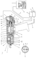
- the pulse screwdriver shown as a hand tool in FIG. 1 has a handle 1 with a pressure switch 2 with which a tilting valve (not shown in the drawing) for the compressed air supply can be actuated.
- a compressed air motor 4 is arranged within a housing 3, which is followed by a pulse unit 5.
- the compressed air supply 6 opens into a compressed air chamber 7 in the housing 3, from where it reaches the compressed air motor. 9 with a centrifugal switch mounted on a motor shaft 8, on which a compression spring 10 surrounding the motor shaft 8 acts.
- This cover 11 is rotatably connected to an opposite cylindrical housing 12 which is on a Output shaft 13 of the pulse unit 5 is mounted.
- the output shaft 13 ends at a short distance from the motor shaft 8 which is axially aligned therewith.
- the cover 11 and the housing 12 define between them a cylinder chamber 14, which is provided eccentrically in the cylinder of the pulse unit 5 delimited by the cover 11 and the housing 12.
- the output shaft 13 passes through this cylinder chamber 14 and is arranged in a conventional manner eccentrically with respect to the axis of this cylinder chamber 14.
- a lamella 15 is radially displaceably accommodated in the output shaft 13, which is under the force of two compression springs 16, which presses the lamella 15 radially outward against the cylindrical wall of the housing 12.
- the output shaft 13 is rotatably mounted with roller bearings 17 and 18 in the motor housing 3, which surrounds the cylindrical casing of the housing 12 of the pulse unit to form an annular gap 19.
- the output shaft 13 receives a tool, not shown here, for example a chuck for screwing tools.
- the cylinder chamber 14 is divided by the lamella 15 in a manner known per se into two chambers, not shown, the cylinder chamber 14 being completely filled with pressure medium, preferably with pressure oil.
- the pressure switch 2 is pressed so that compressed air enters the compressed air chamber 7 to the compressed air motor so that it is driven in a known manner.
- the motor shaft 8 of the compressed air motor 3 drives the cover 11 and the housing 12 as a result of the rotationally fixed mounting.
- the output shaft 13 is rotatably entrained via the pressure oil in the cylinder chamber 14.
- the pulse screwdriver is provided with a frequency setting device 20 which is formed by an adjusting screw 21 which is screwed into a coaxial threaded bore of the output shaft 13.
- the adjusting screw 21 can be easily operated from the outside.
- the adjusting screw 21 extends with a thread-free section into a central bore 22 which penetrates the output shaft 19 and in which an adjusting rod 23 is also received, which is mounted in a bore 24 of the axially aligned motor shaft 8.
- a compression spring 25 is arranged, which is supported at its other end on a shoulder of the adjusting rod 23.
- a measuring sensor in the manner of a strain gauge is on both sides of the bending beam 27 31 recorded, in particular glued on, the signal lines of which are fed to a cable harness 33 received in a stuffing box 32, which leads to an electronic switching element 34.
- One of the transducers absorbs tensile and the other compressive loads.
- a disk-like counter wheel 35 is arranged directly adjacent to the bending beam 27 and is connected to the motor shaft in a rotationally fixed manner.
- This counter wheel 35 acts with a in the housing part 28 together on a flange 36, pin-like sensor 37 which penetrates the annular space 38 of the ring 30 having the bending beam 27.
- the angle of rotation sensor thus formed allows the angle of rotation of the screw or nut to be determined during the screwing-in process.
- the sensor 37 is connected to the stuffing box 32 via a signal line 39 and is supplied to the cable harness 33.
- the bending beam 27, including the fastening ring 30, the sensor 37 and the signal lines in the rear housing part 28 are accommodated in a space-saving and easily accessible manner, and convenient access to the counter wheel 35 is also possible when the rear housing part 28 is removed.
- the end of the actuating rod 23 facing the pulse screwdriver 5, on which the compression spring 25 is supported, is in pressure medium connection with the cylinder chamber 14 via bores, not shown, so that the pressure building up in the cylinder chamber 14 during the screwing process is present on the actuating rod 23. which, depending on the pressure, is pressed correspondingly strongly on the bending beam 27, where the pressure present at the front end of the adjusting rod 23 or the force acting on the bending beam 27 is absorbed by the strain gauges 31 as a bending moment.
- These pressure-dependent bending moments are fed into the cable harness 33 via the line and fed to an electronic control unit 40 via the switching element 34, where the determined bending moment is compared with a predetermined limit torque for the screw connection.
- a signal is given via line 41 to the switching element 34, which actuates an electromagnetic control valve 43 via a control line 42, via which the compressed air supply via line 44 to the compressed air motor 4 is interrupted and the pulse screwdriver is immediately switched off.
- the output shaft 13 stops immediately, so that the screwing tool is actually stopped at the desired limit torque is so that the screw or nut to be tightened is not over-tightened.
- an angle count is carried out via the angle encoder 35, 37, so that the torque and the angle of rotation can be used to increase the security of the correct tightening of a screw connection.
- the angle of rotation and torque at the time of switching off can be compared with a window predetermined by a maximum and minimum torque and certain angles of rotation, the circuit generating a light signal in a specific color or a signal tone if the time of switching off lies in the window defined in this way.
Landscapes
- Engineering & Computer Science (AREA)
- Mechanical Engineering (AREA)
- Details Of Spanners, Wrenches, And Screw Drivers And Accessories (AREA)
Applications Claiming Priority (2)
| Application Number | Priority Date | Filing Date | Title |
|---|---|---|---|
| DE4429282A DE4429282A1 (de) | 1994-08-18 | 1994-08-18 | Hydro-Impulsschrauber insbesondere zum Anziehen von Schraubverbindungen |
| DE4429282 | 1994-08-18 |
Publications (2)
| Publication Number | Publication Date |
|---|---|
| EP0699508A1 true EP0699508A1 (fr) | 1996-03-06 |
| EP0699508B1 EP0699508B1 (fr) | 1998-09-30 |
Family
ID=6525979
Family Applications (1)
| Application Number | Title | Priority Date | Filing Date |
|---|---|---|---|
| EP95110755A Expired - Lifetime EP0699508B1 (fr) | 1994-08-18 | 1995-07-10 | Visseuse à percussion hydraulique notamment pour le serrage de connections filetées |
Country Status (5)
| Country | Link |
|---|---|
| US (1) | US5567886A (fr) |
| EP (1) | EP0699508B1 (fr) |
| CA (1) | CA2156373C (fr) |
| DE (2) | DE4429282A1 (fr) |
| ES (1) | ES2123866T3 (fr) |
Cited By (1)
| Publication number | Priority date | Publication date | Assignee | Title |
|---|---|---|---|---|
| CN105246653A (zh) * | 2013-05-27 | 2016-01-13 | 丰田自动车株式会社 | 控制装置、控制方法和控制程序 |
Families Citing this family (24)
| Publication number | Priority date | Publication date | Assignee | Title |
|---|---|---|---|---|
| DE19617272B4 (de) * | 1995-05-12 | 2005-12-15 | Volkswagen Ag | Verfahren und Vorrichtung zum Herstellen einer Schraubverbindung |
| DE29607207U1 (de) * | 1996-04-20 | 1997-08-21 | Wagner, Paul-Heinz, 53804 Much | Hydraulischer Kraftschrauber |
| DE29615123U1 (de) * | 1996-08-30 | 1998-01-08 | Eduard Wille Gmbh & Co, 42349 Wuppertal | Elektronischer Meßschlüssel |
| US5782158A (en) * | 1996-09-20 | 1998-07-21 | Applied Power Inc. | Air operated hydraulic torque wrench pump |
| US6105595A (en) | 1997-03-07 | 2000-08-22 | Cooper Technologies Co. | Method, system, and apparatus for automatically preventing or allowing flow of a fluid |
| US5894095A (en) * | 1997-04-17 | 1999-04-13 | Demali; Gary W. | Mixing drill with speed sensing with multiple preset speeds |
| US5890848A (en) | 1997-08-05 | 1999-04-06 | Cooper Technologies Company | Method and apparatus for simultaneously lubricating a cutting point of a tool and controlling the application rate of the tool to a work piece |
| US5937370A (en) * | 1997-09-17 | 1999-08-10 | C.E. Electronics, Inc. | Tool monitor and assembly qualifier |
| SE511336C2 (sv) * | 1997-10-27 | 1999-09-13 | Atlas Copco Tools Ab | Metod för fastställande av det installerade momentet i ett skruvförband vid impulsåtdragning, metod för styrning av en åtdragningsprocess, metod för kvalitetsövervakning och ett momentimpulsverktyg för åtdragning av skruvförband |
| FR2771040B1 (fr) * | 1997-11-17 | 2000-01-07 | Serac Group | Procede de commande d'une broche de vissage |
| FR2785986B1 (fr) * | 1998-11-16 | 2000-12-29 | Renault | Procede de mesure et/ou de commande d'un equipement de vissage comprenant une visseuse hydropneumatique a martelement |
| US6318189B1 (en) * | 1998-11-18 | 2001-11-20 | Robert D. Donaldson | Digital torque-responsive pneumatic tool |
| RU2238183C2 (ru) * | 1999-03-16 | 2004-10-20 | Кукен Ко., Лтд. | Способы считывания угла вращения приводимого вручную гайковерта, детектирования биения, определения надежности затягивания резьбы, и управления приводимого вручную отвинчивающего инструмента |
| US6347554B1 (en) * | 2000-02-29 | 2002-02-19 | C.E. Electronics, Inc. | Torque transducer assembly |
| SE519292C2 (sv) * | 2001-04-17 | 2003-02-11 | Atlas Copco Tools Ab | Metod och verktyg innefattande bestämning av överfört moment som funktion av retardation och tröghetsmoment |
| EP1439035A1 (fr) * | 2002-12-16 | 2004-07-21 | Fast Technology AG | Dispositif de traitement et commande de signaux pour un outil dynamometrique motorisé |
| US20050052856A1 (en) * | 2003-09-04 | 2005-03-10 | Sun Microsystems, Inc. | Method and apparatus having field replaceable units with electrical connectors |
| RU2278775C1 (ru) * | 2004-12-20 | 2006-06-27 | Зао "Инструм-Рэнд" | Пневмогидравлический импульсный гайковерт |
| RU2313441C2 (ru) * | 2005-11-25 | 2007-12-27 | Зао "Инструм-Рэнд" | Ударный гайковерт |
| EP2265414A1 (fr) * | 2008-03-17 | 2010-12-29 | Stanley Black & Decker, Inc. | Ensemble outil à entraînement discontinu et procédé permettant de détecter l'angle de rotation de celui-ci |
| JP2010264233A (ja) * | 2009-04-14 | 2010-11-25 | Morita Mfg Co Ltd | 医療用切削装置及びそれを備える医療用切削実習装置 |
| US8393231B2 (en) * | 2010-11-15 | 2013-03-12 | Legend Lifestyle Products Corp. | Multifunctional torque tool detection device |
| TWI498196B (zh) * | 2012-10-05 | 2015-09-01 | China Pneumatic Corp | 間接耦合之扭矩控制方法及其機構 |
| EP3501740A1 (fr) * | 2017-12-20 | 2019-06-26 | HILTI Aktiengesellschaft | Procédé de pose pour raccord à vis au moyen de clé à percussion |
Citations (5)
| Publication number | Priority date | Publication date | Assignee | Title |
|---|---|---|---|---|
| US3440928A (en) * | 1967-09-08 | 1969-04-29 | Ingersoll Rand Co | Impulse tool having shutoff mechanism |
| US3572447A (en) * | 1968-11-12 | 1971-03-30 | Ingersoll Rand Co | Torque measuring system for impact wrench |
| DE2600939A1 (de) | 1976-01-13 | 1977-07-21 | Standard Pressed Steel Co | Anzugssystem mit einem qualitaetspruefgeraet |
| EP0292752A2 (fr) * | 1987-05-26 | 1988-11-30 | Deutsche Gardner-Denver GmbH & Co | Clé à impulsion hydraulique |
| DE4218816A1 (de) * | 1992-06-06 | 1993-12-09 | Gardner Denver Beteiligungsges | Hydroimpulsschrauber mit automatischer Abschaltung |
Family Cites Families (23)
| Publication number | Priority date | Publication date | Assignee | Title |
|---|---|---|---|---|
| US3858444A (en) * | 1973-02-09 | 1975-01-07 | Chicago Pneumatic Tool Co | Angle nut runner with integral torque transducer means of obtaining value of delivered torque |
| US4281538A (en) * | 1973-05-14 | 1981-08-04 | Thor Power Tool Company | Transducer for indicating torque |
| US3920082A (en) * | 1973-05-14 | 1975-11-18 | Thor Power Tool Co | Power tool with torque sensing control means |
| US4286458A (en) * | 1973-10-09 | 1981-09-01 | Rockwell International Corporation | Fastener tools |
| US3969960A (en) * | 1974-05-13 | 1976-07-20 | Dominick A Pagano | Method and apparatus for tightening a bolt to exert a predetermined tension force by monitoring bolt elongation while the bolt is being installed |
| DE2717429A1 (de) * | 1977-04-20 | 1978-10-26 | Wagner Maschf Paul Heinz | Pruefvorrichtung fuer drehmomentenschrauber |
| GB1581101A (en) * | 1978-04-15 | 1980-12-10 | Gkn Fasteners Ltd | Wrench apparatus for tightening a nut and bolt assembly |
| DE3214889A1 (de) * | 1982-04-22 | 1983-10-27 | Robert Bosch Gmbh, 7000 Stuttgart | Messwertgeber fuer drehmoment- und/oder drehwinkelmessung, insbesondere an motorgetriebenen schraubern |
| DE8414766U1 (de) * | 1984-05-15 | 1984-09-13 | Deutsche Gardner-Denver Gmbh, 7081 Westhausen | Schrauber |
| US4604943A (en) * | 1985-02-04 | 1986-08-12 | Ingersoll-Rand Company | Impulse tool having shut off system |
| US4620449A (en) * | 1985-04-23 | 1986-11-04 | The Rotor Tool Company | Portable air tool having built in transducer and calibration assembly |
| US4759225A (en) * | 1987-06-01 | 1988-07-26 | Ryeson Corporation | Torque tool and torque tool analyzer |
| US4969105A (en) * | 1988-05-02 | 1990-11-06 | Ingersoll-Rand Company | Gasket compression control method having tension-related feedback |
| SU1580188A1 (ru) * | 1988-06-15 | 1990-07-23 | Специализированное Конструкторское Бюро По Механизации И Автоматизации Слесарно-Сборочных Работ "Мехинструмент" | Цифровой динамометрический ключ |
| EP0363587B1 (fr) * | 1988-10-12 | 1996-01-24 | Fuji Kuuki Kabushiki Kaisha | Appareil de contrÔle du couple de serrage pour clefs à écrous |
| US4921009A (en) * | 1988-12-07 | 1990-05-01 | Adam Gunter H | Torque control system |
| DE4104352A1 (de) * | 1991-02-13 | 1992-08-20 | Carl Walter Schraubwerkzeug Fa | Drehmomentschluessel |
| JPH04109867U (ja) * | 1991-03-07 | 1992-09-24 | 瓜生製作株式会社 | トルク制御式インパクトレンチ |
| US5315501A (en) * | 1992-04-03 | 1994-05-24 | The Stanley Works | Power tool compensator for torque overshoot |
| DE4237968C2 (de) * | 1992-10-26 | 1996-05-30 | Grass Ag | Trennwandelement zur Schubladeneinteilung von Schubladen |
| SE500541C2 (sv) * | 1992-12-07 | 1994-07-11 | Atlas Copco Controls Ab | Momentalstrande kraftverktyg |
| DE4243069C2 (de) * | 1992-12-18 | 2001-09-27 | Gardner Denver Gmbh | Impulswerkzeug, insbesondere Impulsschrauber |
| DE9405525U1 (de) * | 1994-03-31 | 1994-06-09 | Lo, Juey Yuan, Yung Ho, Taipeh | Kraftbetriebenes Werkzeug mit automatischer Überlastauslösung und Leistungsabschaltung |
-
1994
- 1994-08-18 DE DE4429282A patent/DE4429282A1/de not_active Withdrawn
-
1995
- 1995-07-10 ES ES95110755T patent/ES2123866T3/es not_active Expired - Lifetime
- 1995-07-10 EP EP95110755A patent/EP0699508B1/fr not_active Expired - Lifetime
- 1995-07-10 DE DE59503770T patent/DE59503770D1/de not_active Expired - Fee Related
- 1995-08-17 US US08/516,327 patent/US5567886A/en not_active Expired - Fee Related
- 1995-08-17 CA CA002156373A patent/CA2156373C/fr not_active Expired - Fee Related
Patent Citations (6)
| Publication number | Priority date | Publication date | Assignee | Title |
|---|---|---|---|---|
| US3440928A (en) * | 1967-09-08 | 1969-04-29 | Ingersoll Rand Co | Impulse tool having shutoff mechanism |
| US3572447A (en) * | 1968-11-12 | 1971-03-30 | Ingersoll Rand Co | Torque measuring system for impact wrench |
| DE2600939A1 (de) | 1976-01-13 | 1977-07-21 | Standard Pressed Steel Co | Anzugssystem mit einem qualitaetspruefgeraet |
| EP0292752A2 (fr) * | 1987-05-26 | 1988-11-30 | Deutsche Gardner-Denver GmbH & Co | Clé à impulsion hydraulique |
| EP0292752B1 (fr) | 1987-05-26 | 1994-04-13 | Deutsche Gardner-Denver GmbH & Co | Clé à impulsion hydraulique |
| DE4218816A1 (de) * | 1992-06-06 | 1993-12-09 | Gardner Denver Beteiligungsges | Hydroimpulsschrauber mit automatischer Abschaltung |
Cited By (2)
| Publication number | Priority date | Publication date | Assignee | Title |
|---|---|---|---|---|
| CN105246653A (zh) * | 2013-05-27 | 2016-01-13 | 丰田自动车株式会社 | 控制装置、控制方法和控制程序 |
| CN105246653B (zh) * | 2013-05-27 | 2017-05-17 | 丰田自动车株式会社 | 控制装置、控制方法和控制程序 |
Also Published As
| Publication number | Publication date |
|---|---|
| CA2156373A1 (fr) | 1996-02-19 |
| DE4429282A1 (de) | 1996-02-22 |
| EP0699508B1 (fr) | 1998-09-30 |
| US5567886A (en) | 1996-10-22 |
| DE59503770D1 (de) | 1998-11-05 |
| CA2156373C (fr) | 1998-05-12 |
| ES2123866T3 (es) | 1999-01-16 |
Similar Documents
| Publication | Publication Date | Title |
|---|---|---|
| EP0699508B1 (fr) | Visseuse à percussion hydraulique notamment pour le serrage de connections filetées | |
| EP0182986B1 (fr) | Dispositif de serrage actionné par moteur avec réglage du couple variable | |
| EP0042548B1 (fr) | Dispositif de vissage à détection du couple | |
| DE2462678C3 (de) | Gehäuseausbildung für ein kraftbetätigtes Werkzeug, insbesondere Drehschrauber | |
| EP3737533B1 (fr) | Mécanisme de déclenchement pour un outil de couple | |
| EP0164574A2 (fr) | Dispositif de vissage | |
| EP3820649B1 (fr) | Ensemble de visseuse dynamométrique et procédé de fonctionnement d'un tel ensemble de visseuse dynamométrique | |
| DE1478904A1 (de) | Drehschlagschrauber | |
| DE1218370B (de) | Motorisch angetriebenes, insbesondere tragbares Schraubgeraet | |
| EP0858382A1 (fr) | Tournevis a moteur muni d'un dispositif amortisseur situe entre la poignee gainee et le boitier | |
| DE202018102716U1 (de) | Elektronischer Drehmomentschlüssel mit einer Messanordnung | |
| EP2113341B1 (fr) | Visseuse sous pression | |
| DE3824372A1 (de) | Getriebe mit ueberlastsicherung, insbesondere fuer kettenantriebe bei bergbaumaschinen, wie vor allem kohlenhobel | |
| EP0904178A1 (fr) | Cle a chocs hydraulique | |
| DE2557114A1 (de) | Kupplung mit drehmomentbegrenzung | |
| DE4210201A1 (de) | Schrauber, insbesondere Druckluftschrauber | |
| DE102017004043A1 (de) | Drehmomentschlüssel mit vordefinierter Drehmomentbegrenzung | |
| DE3402501A1 (de) | Schrauber | |
| DE10163287B4 (de) | Verfahren und Vorrichtung zum Prüfen des Abschaltverhaltens von streckgrenzgesteuerten Kraftschraubern | |
| DD219143A1 (de) | Tragbarer kraftangetriebener schrauber mit drehmomentanzeige | |
| DE19901449B4 (de) | Vorrichtung zum Einstellen bzw. Eichen von Schraubern | |
| DE4218816C2 (de) | Hydroimpulsschrauber | |
| DE202019100283U1 (de) | Drehmomentsteuervorrichtung für einen elektrischen Schraubendreher | |
| EP0929380A1 (fr) | Tourne-vis amplificateur de couple | |
| DE3518103C2 (fr) |
Legal Events
| Date | Code | Title | Description |
|---|---|---|---|
| PUAI | Public reference made under article 153(3) epc to a published international application that has entered the european phase |
Free format text: ORIGINAL CODE: 0009012 |
|
| AK | Designated contracting states |
Kind code of ref document: A1 Designated state(s): DE ES FR GB IT SE |
|
| 17P | Request for examination filed |
Effective date: 19960904 |
|
| GRAG | Despatch of communication of intention to grant |
Free format text: ORIGINAL CODE: EPIDOS AGRA |
|
| 17Q | First examination report despatched |
Effective date: 19970917 |
|
| GRAG | Despatch of communication of intention to grant |
Free format text: ORIGINAL CODE: EPIDOS AGRA |
|
| GRAH | Despatch of communication of intention to grant a patent |
Free format text: ORIGINAL CODE: EPIDOS IGRA |
|
| GRAH | Despatch of communication of intention to grant a patent |
Free format text: ORIGINAL CODE: EPIDOS IGRA |
|
| GRAA | (expected) grant |
Free format text: ORIGINAL CODE: 0009210 |
|
| AK | Designated contracting states |
Kind code of ref document: B1 Designated state(s): DE ES FR GB IT SE |
|
| GBT | Gb: translation of ep patent filed (gb section 77(6)(a)/1977) |
Effective date: 19981001 |
|
| REF | Corresponds to: |
Ref document number: 59503770 Country of ref document: DE Date of ref document: 19981105 |
|
| ET | Fr: translation filed | ||
| REG | Reference to a national code |
Ref country code: ES Ref legal event code: FG2A Ref document number: 2123866 Country of ref document: ES Kind code of ref document: T3 |
|
| PLBE | No opposition filed within time limit |
Free format text: ORIGINAL CODE: 0009261 |
|
| STAA | Information on the status of an ep patent application or granted ep patent |
Free format text: STATUS: NO OPPOSITION FILED WITHIN TIME LIMIT |
|
| 26N | No opposition filed | ||
| REG | Reference to a national code |
Ref country code: GB Ref legal event code: IF02 |
|
| PGFP | Annual fee paid to national office [announced via postgrant information from national office to epo] |
Ref country code: GB Payment date: 20030612 Year of fee payment: 9 |
|
| PGFP | Annual fee paid to national office [announced via postgrant information from national office to epo] |
Ref country code: FR Payment date: 20030702 Year of fee payment: 9 |
|
| PGFP | Annual fee paid to national office [announced via postgrant information from national office to epo] |
Ref country code: SE Payment date: 20030703 Year of fee payment: 9 |
|
| PGFP | Annual fee paid to national office [announced via postgrant information from national office to epo] |
Ref country code: ES Payment date: 20030723 Year of fee payment: 9 |
|
| PGFP | Annual fee paid to national office [announced via postgrant information from national office to epo] |
Ref country code: DE Payment date: 20030731 Year of fee payment: 9 |
|
| PG25 | Lapsed in a contracting state [announced via postgrant information from national office to epo] |
Ref country code: GB Free format text: LAPSE BECAUSE OF NON-PAYMENT OF DUE FEES Effective date: 20040710 |
|
| PG25 | Lapsed in a contracting state [announced via postgrant information from national office to epo] |
Ref country code: SE Free format text: LAPSE BECAUSE OF NON-PAYMENT OF DUE FEES Effective date: 20040711 |
|
| PG25 | Lapsed in a contracting state [announced via postgrant information from national office to epo] |
Ref country code: ES Free format text: LAPSE BECAUSE OF NON-PAYMENT OF DUE FEES Effective date: 20040712 |
|
| PG25 | Lapsed in a contracting state [announced via postgrant information from national office to epo] |
Ref country code: DE Free format text: LAPSE BECAUSE OF NON-PAYMENT OF DUE FEES Effective date: 20050201 |
|
| EUG | Se: european patent has lapsed | ||
| GBPC | Gb: european patent ceased through non-payment of renewal fee |
Effective date: 20040710 |
|
| PG25 | Lapsed in a contracting state [announced via postgrant information from national office to epo] |
Ref country code: FR Free format text: LAPSE BECAUSE OF NON-PAYMENT OF DUE FEES Effective date: 20050331 |
|
| REG | Reference to a national code |
Ref country code: FR Ref legal event code: ST |
|
| PG25 | Lapsed in a contracting state [announced via postgrant information from national office to epo] |
Ref country code: IT Free format text: LAPSE BECAUSE OF NON-PAYMENT OF DUE FEES;WARNING: LAPSES OF ITALIAN PATENTS WITH EFFECTIVE DATE BEFORE 2007 MAY HAVE OCCURRED AT ANY TIME BEFORE 2007. THE CORRECT EFFECTIVE DATE MAY BE DIFFERENT FROM THE ONE RECORDED. Effective date: 20050710 |
|
| REG | Reference to a national code |
Ref country code: ES Ref legal event code: FD2A Effective date: 20040712 |