EP0699565A2 - Batterieklemme mit Sicherung für Kraftfahrzeuge und ihre Verbindung - Google Patents
Batterieklemme mit Sicherung für Kraftfahrzeuge und ihre Verbindung Download PDFInfo
- Publication number
- EP0699565A2 EP0699565A2 EP95305931A EP95305931A EP0699565A2 EP 0699565 A2 EP0699565 A2 EP 0699565A2 EP 95305931 A EP95305931 A EP 95305931A EP 95305931 A EP95305931 A EP 95305931A EP 0699565 A2 EP0699565 A2 EP 0699565A2
- Authority
- EP
- European Patent Office
- Prior art keywords
- fuse
- connection
- link
- section
- battery
- Prior art date
- Legal status (The legal status is an assumption and is not a legal conclusion. Google has not performed a legal analysis and makes no representation as to the accuracy of the status listed.)
- Granted
Links
- 239000000463 material Substances 0.000 claims description 18
- 230000007704 transition Effects 0.000 claims description 10
- 238000012546 transfer Methods 0.000 claims description 5
- 239000000155 melt Substances 0.000 claims description 4
- 239000004020 conductor Substances 0.000 claims 7
- 238000005452 bending Methods 0.000 claims 2
- 230000008602 contraction Effects 0.000 claims 2
- 230000014759 maintenance of location Effects 0.000 claims 1
- 238000007664 blowing Methods 0.000 description 12
- ATJFFYVFTNAWJD-UHFFFAOYSA-N Tin Chemical compound [Sn] ATJFFYVFTNAWJD-UHFFFAOYSA-N 0.000 description 7
- 238000002844 melting Methods 0.000 description 5
- 230000008018 melting Effects 0.000 description 5
- 238000013461 design Methods 0.000 description 4
- 239000011324 bead Substances 0.000 description 3
- 229910001128 Sn alloy Inorganic materials 0.000 description 2
- 230000008859 change Effects 0.000 description 2
- 230000000694 effects Effects 0.000 description 2
- 239000002184 metal Substances 0.000 description 2
- 238000007665 sagging Methods 0.000 description 2
- 229910001369 Brass Inorganic materials 0.000 description 1
- 229910045601 alloy Inorganic materials 0.000 description 1
- 239000000956 alloy Substances 0.000 description 1
- 238000004873 anchoring Methods 0.000 description 1
- 230000008901 benefit Effects 0.000 description 1
- 239000010951 brass Substances 0.000 description 1
- 238000010276 construction Methods 0.000 description 1
- 238000010309 melting process Methods 0.000 description 1
- 238000000034 method Methods 0.000 description 1
- 238000012986 modification Methods 0.000 description 1
- 230000004048 modification Effects 0.000 description 1
- 230000008569 process Effects 0.000 description 1
- 230000000717 retained effect Effects 0.000 description 1
- 239000007787 solid Substances 0.000 description 1
- 238000012360 testing method Methods 0.000 description 1
- 230000008016 vaporization Effects 0.000 description 1
- 238000009834 vaporization Methods 0.000 description 1
- 238000003466 welding Methods 0.000 description 1
Images


Classifications
-
- H—ELECTRICITY
- H01—ELECTRIC ELEMENTS
- H01R—ELECTRICALLY-CONDUCTIVE CONNECTIONS; STRUCTURAL ASSOCIATIONS OF A PLURALITY OF MUTUALLY-INSULATED ELECTRICAL CONNECTING ELEMENTS; COUPLING DEVICES; CURRENT COLLECTORS
- H01R11/00—Individual connecting elements providing two or more spaced connecting locations for conductive members which are, or may be, thereby interconnected, e.g. end pieces for wires or cables supported by the wire or cable and having means for facilitating electrical connection to some other wire, terminal, or conductive member, blocks of binding posts
- H01R11/11—End pieces or tapping pieces for wires, supported by the wire and for facilitating electrical connection to some other wire, terminal or conductive member
- H01R11/28—End pieces consisting of a ferrule or sleeve
- H01R11/281—End pieces consisting of a ferrule or sleeve for connections to batteries
- H01R11/283—Bolt, screw or threaded ferrule parallel to the battery post
-
- B—PERFORMING OPERATIONS; TRANSPORTING
- B60—VEHICLES IN GENERAL
- B60R—VEHICLES, VEHICLE FITTINGS, OR VEHICLE PARTS, NOT OTHERWISE PROVIDED FOR
- B60R16/00—Electric or fluid circuits specially adapted for vehicles and not otherwise provided for; Arrangement of elements of electric or fluid circuits specially adapted for vehicles and not otherwise provided for
- B60R16/02—Electric or fluid circuits specially adapted for vehicles and not otherwise provided for; Arrangement of elements of electric or fluid circuits specially adapted for vehicles and not otherwise provided for electric constitutive elements
- B60R16/04—Arrangement of batteries
-
- H—ELECTRICITY
- H01—ELECTRIC ELEMENTS
- H01H—ELECTRIC SWITCHES; RELAYS; SELECTORS; EMERGENCY PROTECTIVE DEVICES
- H01H85/00—Protective devices in which the current flows through a part of fusible material and this current is interrupted by displacement of the fusible material when this current becomes excessive
- H01H85/02—Details
- H01H85/04—Fuses, i.e. expendable parts of the protective device, e.g. cartridges
- H01H85/041—Fuses, i.e. expendable parts of the protective device, e.g. cartridges characterised by the type
- H01H85/044—General constructions or structure of low voltage fuses, i.e. below 1000 V, or of fuses where the applicable voltage is not specified
-
- H—ELECTRICITY
- H01—ELECTRIC ELEMENTS
- H01H—ELECTRIC SWITCHES; RELAYS; SELECTORS; EMERGENCY PROTECTIVE DEVICES
- H01H85/00—Protective devices in which the current flows through a part of fusible material and this current is interrupted by displacement of the fusible material when this current becomes excessive
- H01H85/02—Details
- H01H85/0241—Structural association of a fuse and another component or apparatus
- H01H2085/025—Structural association with a binding post of a storage battery
-
- H—ELECTRICITY
- H01—ELECTRIC ELEMENTS
- H01R—ELECTRICALLY-CONDUCTIVE CONNECTIONS; STRUCTURAL ASSOCIATIONS OF A PLURALITY OF MUTUALLY-INSULATED ELECTRICAL CONNECTING ELEMENTS; COUPLING DEVICES; CURRENT COLLECTORS
- H01R11/00—Individual connecting elements providing two or more spaced connecting locations for conductive members which are, or may be, thereby interconnected, e.g. end pieces for wires or cables supported by the wire or cable and having means for facilitating electrical connection to some other wire, terminal, or conductive member, blocks of binding posts
- H01R11/11—End pieces or tapping pieces for wires, supported by the wire and for facilitating electrical connection to some other wire, terminal or conductive member
- H01R11/28—End pieces consisting of a ferrule or sleeve
- H01R11/281—End pieces consisting of a ferrule or sleeve for connections to batteries
- H01R11/287—Intermediate parts between battery post and cable end piece
Definitions
- This invention relates to an automotive fuse-link and to a battery terminal incorporating a fuse-link.
- Objects of this invention have been achieved by providing a fuse assembly for interconnecting power supply lines to an automobile battery, the fuse assembly having a stamped and formed sheet metal terminal comprising a supply line interconnection portion and a battery terminal portion connected via a fuse link that is blowable when subjected to sufficiently high electrical current, whereby the battery portion comprises an integral battery post connection portion insertable over a battery post of an automobile battery for electrical connection thereto.
- a fuse-link comprising a first high temperature conductive base member and a second high temperature conductive base member, each of the base members having a support bar to which a fusible material is attached and interlink the support bars of the first and second base members.
- the fusible material has a lower temperature melting point than the high temperature material such that it melts and falls off the support bars when excessive electrical current flows therethrough, thereby breaking the electrical connection between the first and second base members.
- the support bars are substantially interlinked only by the fusible material which could be made of tin, or tin alloy.
- the support part can advantageously be attached to the base members via a reduced width section that can be adjusted in width and length for mainly varying the heat transfer from the support bar to the base members in order to control the fuse-blowing characteristics.
- a preferred embodiment of this invention also comprises an insulative support platform to which the power supply and battery portions of the terminal plate are securely fixed, whereby threaded mounting bolts are securely attached to the support member, for example inmoulded, to allow secure tightening of the power supply lines against the fuse terminal and power supply portions.
- a fused battery terminal 2 comprising a support member 4, a stamped and formed electrical terminal member 6 and battery post mounting members 8.
- the battery post mounting member 8 has a rotatable cap 10 that cooperates with conical jaws for clamping onto a battery post of an automobile battery.
- the mounting member is a known design and is not explained here in any detail.
- the terminal member 6 could be interconnected to the battery post by any other mounting means.
- the support member 4 comprises an insulative moulded housing 12, an insulative fuse cover 14 (see Figures 15 and 16), and power and safety supply bolts 18, 16 having head portions 20 inmoulded to the insulative housing 12.
- the support member 4 has a first power supply section 22 and a second battery terminal section 24 separated by a fuse section 25 extending therebetween.
- the power supply connection bolt 18 is inmoulded to the first section 22 and the other safety power supply bolt 16 is inmoulded to the second section 24.
- Both first and second section 22, 25 comprise pairs of retaining walls 26 extending outwardly from opposing side surfaces 28, 30 of the housing 12.
- the fuse section 25 has an upper surface 32 which is recessed with respect to the upper surface 34 of sections 22, 24.
- the fuse section 26 further comprises a pair of mounting cavities 36 for receiving pins 36 of the cover 14 (see Figures 15 and 16) for mounting of the cover thereto.
- the cover 14 has mounting surfaces 40 surrounding the base of the mounting pins 38 and a fuse cover surface 42 which is recessed with respect to the surfaces 40.
- the bolt 18 is shown comprising a threaded portion 44 and the head portion 20 which has a cylindrical anchoring portion 46 for supporting the bolt within the overmoulded housing 12, and a hexagonal extension 48 for preventing rotation of the bolt within the housing.
- the bolt 16 has a smaller diameter than the bolt 18 but has a head of a similar construction to that of the bolt 18.
- the terminal member 6 is shown having a first section 50 and a second section 52 separated by a fuse link 54.
- the first terminal section 50 comprises a connection platform 56 from which extend four mounting tabs 58, the connection platform 56 comprising a hole 60 for receiving the bolt 18 therethrough.
- the second terminal section 52 similarly comprises a connection platform 62 from which extend mounting tabs 64, the connection platform 62 also comprising a hole 66 for receiving the bolt 16 therethrough.
- the second terminal section 52 is integrally attached to a battery post connection section 68 to which the battery post mounting member 8 is mechanically and electrically connected.
- connection section 58 comprises mounting member fixing tabs 70 extending outwardly from a circular base portion 72, the base portion having a circular cutout 74 for mounting over and around the battery post.
- the cutout 74 is bounded by a truncated conical section 76 that extends upwards from the base section 72.
- the fuse link 54 is coined such that it has a material thickness thinner than the sheet metal from which the terminal member 6 is stamped and formed (as best shown in Figure 7), the fuse link having a thin central section 80 which is the point of highest resistance thereby melting and breaking the electrical circuit when subjected to excessive electrical current.
- the terminal member 6 is shown mounted to the support member 4 whereby the mounting arms 58 are wrapped around the sides 24, 30 of the housing 12 and are retained from forward and rearward movement by retaining walls 26 which help to strengthen and protect the tabs from damage once wrapped around the housing 12.
- the fuse cover 14 is then mounted to the housing 12, and the pins 38 are bonded to the holes 36 by an ultrasonic welding process such that the fuse link 54 is protected from damage and deposits of material from the environment that may alter it's fuse blowing characteristics.
- the housing and cover recesses 32, 42 allow a sufficient gap to the fuse link such that during the melting process the fuse link does not sag and enter into contact with the cover or housing which would alter the fuse blowing characteristics.
- Power supply connections can thus be bolted to the bolt 18 and pressed against the terminal connection platform 56 thereby electrically connecting the power supply lines to the battery terminal via the fuse link 54.
- Certain electrical components such as the airbag, must function at any moment, and are therefore connected directly to the battery post by being clamped around the bolt 16 against the connection platform 62 which has a direct connection to the battery terminal. If the fuse link 54 blows due to a short circuit in the main power supply of the automobile, the safety functions will nevertheless still be connected to the battery.
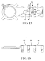
- FIG. 17 another embodiment is illustrated whereby an alternative fuse link 54' having a thin central section 80' that flows when excessive current flows therethrough.
- the fuse link 54' comprises a U-shaped portion 82 that comprises a pair of spaced apart extensions 84 connected to a connection platform 62' at first ends 86 thereof and connected to a transverse bar 88 extending between other ends 91 thereof.
- the fuse link 54' further comprises a central bar 90 that extends between a central position on the transverse bar 88 and a terminal connection platform 56' similar to the terminal connection platform 56 of the previous embodiment.
- the central bar 90 comprises the central portion 80' which has a central hole filled with a tin bead 92, the central portion 80' further comprising indents 94 for thinning the cross-section between the bead and outer edges 96 of the central bar 90.
- a tin bead is known for example in U.S. Patent 2,055,866, and has the effect of reducing the blowing temperature of the fuse link by producing a different alloy when melting, thus improving the blowing characteristics of the fuse link.
- the lower blowing temperature also reduces the sagging effect of the fuse link which, if it touches the support member 32, may cool down and not blow at the required electrical current.
- the U-shaped element 82 is particularly advantageous in that it provides a sturdy support for the central fuse bar 90 by being supported at two spaced apart points, whilst nevertheless allowing expansion of the central bar 90 due to thermal digitation, in particular because the central bar is connected to a central position on the transverse bar 88 which can thus bend inwards to allow for expansion. Thermal dilatation must be compensated for as the fuse link may otherwise bend excessively and either break prematurely or touch the supports surrounding it, or possibly by other means change the blowing characteristics.
- the above design provides a sturdy support for the fusing bar 90 whilst nevertheless allowing thermal digitation.
- the battery terminal member 6 is integrally connected to the battery post connection portion 68, and the power supply connection sections 50, 52 are strongly and rigidly held to a support member 4 that allows reliable and simple clamping of power supply lines to either end of the fuse link whilst providing a rigid and safe support for the fuse link 54 therebetween.
- FIG. 19 another embodiment of a fuse battery terminal 102 is shown comprising a support member 104, a stamped and formed electrical terminal member 106, and battery post mounting members 108.
- the terminal member 106 comprises a first connection section 150 and a second battery terminal section 152 separated by a fuse-link 154.
- the first and second sections 150,152 comprise mounting tabs 164 for mounting to the support member 104 in a similar manner to that described in the embodiment of Figures 1-18.
- the fuse battery terminal 102 differs from the fuse terminal 2 principally in the fuse link section 154 of the terminal member 106 and in the fuse section 125 of the support member 104 as will be described hereinafter.
- the battery post connection section 168 in the embodiments of Figure 22 also differs in that it is attached to a lateral extension extending from the terminal section 152. The position of the battery post connection section 168,68 will depend on the particular geometrical requirements of the particular application.
- the fuse-link section 154 comprises a fuse portion 180 which is a bar of fusible material, the material being of tin or tin alloy for example, interlinking support bars 181,183.
- the fuse portion 180 can be attached, for example, by reflow of the tin between the support bars.
- the support portions 181,183 had a width W2 and are integrally linked to respective base sections 150,152 via reduced width transition portions 185,187 respectively.
- the fusible material bar 180 has a lower melting point than the base sections and support portion material which could be, for example, brass.
- the reduced width transition portions 185,187 have a certain width W1 and a certain length L that can be varied to adjust the quantity of heat transfer through the transition portions from the fuse-link section.
- the rate of heat transfer flowing out of the fuse portion 180 will determine the blowing characteristics thereof.
- Changing the width and length of the transition portions 185,187 can be effectuated by simple changes to the stamping die from which the terminal member is stamped, thus making it easy to change the characteristics if required, as well as providing easily measurable parameters that can be directly measured and linked to their corresponding test curves, thus making it easy to control the design of the fuse and any modifications required by changes in the specifications.
- the bar of fusible material 180 melts and falls off (or is blown off) the support bars 181,183 by gravitational force (or vaporization). If the fusible material does not fall off by gravitation, it will vaporize and blow off the support members because molten tin has an electrical resistance about three times greater than when in the solid state, so it will heat up very rapidly once in the molten state.
- the fuse-link 154 does not provide an integral interconnection between the support members 181,183, rather the fusible bar of material 180 spans fully across the whole length of the support bar such that no connection between the support bars subsists once the molten tin has fallen off.
- the blowing characteristics of the fuse-link is more reliable in this way as integral links between the support members may not blow sufficiently quickly at very high current peaks.
- the housing support member 104 comprises upstanding pins 127 projecting from the fuse section 125 below the fuse-link section 154 of the terminal member 106 when mounted to the support member.
- a cover member 114 that is mountable over the fuse-link 154 and securely fixable to the support member 104 also comprises pins 129 projecting from a top wall 142 of the cover 114 towards the terminal member fuse-link section 154.
- the pins 127,129 serve to capture the molten fusible material when it drops off the support bars 181,183 to prevent the fusible material from flowing and accidentally reconnecting the first and second sections 150,152 of the terminal member.
- the cover 114 is securely attached to the support member 104 by interengaging latching means 131,133 which allows quick assembly thereof.
- the provision of support bars integrally interconnected to respective sections of the terminal via reduced width portions, and provided with a fusible material with low melting point temperature spanning across the whole width of the support members provides a very high temperature fuse with finely adjustable blowing characteristics. Furthermore, there is no risk of sagging or other such problems related to fuses where the support bars are integrally interlinked.
Landscapes
- Engineering & Computer Science (AREA)
- Mechanical Engineering (AREA)
- Fuses (AREA)
- Connection Of Batteries Or Terminals (AREA)
Applications Claiming Priority (5)
| Application Number | Priority Date | Filing Date | Title |
|---|---|---|---|
| FR9410258 | 1994-08-24 | ||
| FR9410258A FR2724064A1 (fr) | 1994-08-24 | 1994-08-24 | Connecteur pour batterie d'automobile comportant un fusible |
| FR9503966 | 1995-04-04 | ||
| FR9503966A FR2732823A1 (fr) | 1995-04-04 | 1995-04-04 | Connecteur pour batterie d'automobile comportant un fusible |
| US08/521,678 US5805047A (en) | 1994-08-24 | 1995-08-31 | Fused car battery terminal and fuse-link therefor |
Publications (3)
| Publication Number | Publication Date |
|---|---|
| EP0699565A2 true EP0699565A2 (de) | 1996-03-06 |
| EP0699565A3 EP0699565A3 (de) | 1996-12-11 |
| EP0699565B1 EP0699565B1 (de) | 2000-12-13 |
Family
ID=27252957
Family Applications (1)
| Application Number | Title | Priority Date | Filing Date |
|---|---|---|---|
| EP95305931A Expired - Lifetime EP0699565B1 (de) | 1994-08-24 | 1995-08-24 | Batterieklemme mit Sicherung für Kraftfahrzeuge und ihre Verbindung |
Country Status (4)
| Country | Link |
|---|---|
| US (1) | US5805047A (de) |
| EP (1) | EP0699565B1 (de) |
| DE (1) | DE69519611T2 (de) |
| ES (1) | ES2152366T3 (de) |
Cited By (6)
| Publication number | Priority date | Publication date | Assignee | Title |
|---|---|---|---|---|
| WO1997040510A1 (de) * | 1996-04-19 | 1997-10-30 | Trw Automotive Electronics & Components Gmbh & Co. | Sicherungsbox für kraftfahrzeuge |
| EP0932223A1 (de) * | 1998-01-22 | 1999-07-28 | The Whitaker Corporation | Hochleistungssicherung |
| EP1103998A3 (de) * | 1999-11-25 | 2002-06-12 | Yazaki Corporation | Verbinderstruktur für eine Schmelzsicherung und Anschlussklemmen |
| US6512443B1 (en) * | 1999-05-18 | 2003-01-28 | Yazaki Corporation | Large current fuse for direct coupling to power source |
| WO2012163730A1 (de) * | 2011-05-31 | 2012-12-06 | Lisa Dräxlmaier GmbH | Abgewinkelte midi- oder schmelzsicherung |
| WO2015034599A1 (en) * | 2013-09-06 | 2015-03-12 | Johnson Controls Technology Company | Bladed fuse connectors for use in a vehicle battery module |
Families Citing this family (34)
| Publication number | Priority date | Publication date | Assignee | Title |
|---|---|---|---|---|
| JP2993933B1 (ja) * | 1998-06-23 | 1999-12-27 | 東洋システム株式会社 | 温度ヒューズ機能付き導電接触ピン |
| DE19963622A1 (de) * | 1999-12-29 | 2001-07-12 | Bosch Gmbh Robert | Elektrische Sicherung für Drehstromgeneratoren mit Gleichrichter |
| JP4083991B2 (ja) * | 2000-02-09 | 2008-04-30 | 矢崎総業株式会社 | ヒューズユニットとその製造方法 |
| DE10012387C2 (de) * | 2000-03-14 | 2002-10-02 | Itt Mfg Enterprises Inc | Anordnung zum Verbinden eines Kabels mit einem Kraftfahrzeugbatteriepol |
| US6607860B2 (en) | 2001-01-24 | 2003-08-19 | Ewd, L.L.C. | Serviceable fused battery terminal |
| JP3845266B2 (ja) * | 2001-05-01 | 2006-11-15 | 矢崎総業株式会社 | ヒューズユニット |
| US6809625B2 (en) * | 2001-12-20 | 2004-10-26 | Intel Corporation | Integrated connector and positive thermal coefficient switch |
| DE102004052476B4 (de) * | 2003-10-31 | 2007-08-09 | Yazaki Corp. | Sicherungsanordnung |
| US6932650B1 (en) * | 2004-03-25 | 2005-08-23 | Royal Die & Stamping Co., Inc. | Fused battery terminal connector |
| US7172462B1 (en) | 2005-08-15 | 2007-02-06 | Yazaki North America, Inc. | Fuse |
| US7924137B2 (en) * | 2007-09-10 | 2011-04-12 | Cooper Technologies Company | Battery fuse assembly |
| US7663466B1 (en) * | 2007-09-21 | 2010-02-16 | Yazaki North America, Inc. | Corner-mounted battery fuse |
| JP5189920B2 (ja) * | 2008-07-25 | 2013-04-24 | 矢崎総業株式会社 | ヒュージブルリンクユニット |
| CN102103949B (zh) * | 2009-12-18 | 2015-01-14 | 庄嘉明 | 具连结缓冲结构的保险丝元件及具有该保险丝的电源模组 |
| JP5422424B2 (ja) * | 2010-02-03 | 2014-02-19 | 矢崎総業株式会社 | ヒューズユニット |
| JP5418846B2 (ja) * | 2010-02-03 | 2014-02-19 | 株式会社オートネットワーク技術研究所 | 過電流遮断素子付き端子 |
| JP5422429B2 (ja) * | 2010-02-10 | 2014-02-19 | 矢崎総業株式会社 | ヒューズユニット |
| JP5590707B2 (ja) * | 2010-03-08 | 2014-09-17 | 矢崎総業株式会社 | バッテリ直付けヒュージブルリンク |
| JP5486993B2 (ja) * | 2010-04-06 | 2014-05-07 | 矢崎総業株式会社 | ヒューズユニット |
| US8665056B2 (en) | 2010-05-18 | 2014-03-04 | Littlefuse, Inc. | Fuse assembly |
| US8669840B2 (en) * | 2010-05-18 | 2014-03-11 | Littelfuse, Inc. | Fuse assembly |
| JP5670769B2 (ja) * | 2011-01-26 | 2015-02-18 | 矢崎総業株式会社 | ヒューズユニット |
| SI23826A (sl) * | 2011-08-18 | 2013-02-28 | Hidria AET Družba za proizvodnjo vžigalnih sistemov in elektronike d.o.o. | Varovalka grelnika zraka diesel motorjev |
| KR101272555B1 (ko) | 2011-12-05 | 2013-06-11 | 주식회사 경신 | 배터리 퓨즈 터미널 장치 |
| JP6059496B2 (ja) * | 2012-10-03 | 2017-01-11 | 矢崎総業株式会社 | バッテリ端子の接続構造 |
| JP5973334B2 (ja) * | 2012-12-11 | 2016-08-23 | ナブテスコ株式会社 | 端子接続継ぎ手および端子台 |
| RS61754B1 (sr) | 2015-03-12 | 2021-05-31 | Aees Inc | Sklop priključne stezaljke niskog profila |
| CN106356655A (zh) * | 2016-09-28 | 2017-01-25 | 深圳供电局有限公司 | 一种低压开关防倒供电装置 |
| US10333129B2 (en) * | 2017-01-26 | 2019-06-25 | Te Connectivity Corporation | Buss bar assembly for a battery system |
| US10008789B1 (en) | 2017-07-10 | 2018-06-26 | Royal Die & Stamping, Llc | Angled bolt T-bar battery terminal clamp |
| CN111095469B (zh) * | 2017-09-22 | 2022-05-06 | 力特保险丝公司 | 集成熔断器模块 |
| WO2019166897A1 (en) * | 2018-02-28 | 2019-09-06 | Yazaki India Private Limited | Battery fuse terminal for vehicles |
| US10916897B1 (en) | 2020-02-13 | 2021-02-09 | Aees Inc. | Battery mounted fuse holder |
| US11195683B1 (en) * | 2021-02-11 | 2021-12-07 | Littelfuse, Inc. | Single bolt fuse assembly with an electrically isolated bolt |
Family Cites Families (22)
| Publication number | Priority date | Publication date | Assignee | Title |
|---|---|---|---|---|
| USRE18128E (en) * | 1931-07-14 | Renewable fuse element | ||
| US2055866A (en) * | 1932-07-01 | 1936-09-29 | Oscar H Jung | Electric fuse |
| GB549578A (en) * | 1941-05-21 | 1942-11-27 | Herbert Astbury | Improvements in or relating to electric fuses |
| US2376809A (en) * | 1941-11-07 | 1945-05-22 | Westinghouse Electric & Mfg Co | Circuit interrupter |
| US2561464A (en) * | 1945-10-05 | 1951-07-24 | Forges Ateliers Const Electr | Time lag fuse |
| US2502747A (en) * | 1946-07-26 | 1950-04-04 | Pierce Renewable Fuses Inc | Electric fuse |
| US2727110A (en) * | 1953-12-22 | 1955-12-13 | Gen Electric | Time-delay motor protective fuse |
| US2773961A (en) * | 1954-04-28 | 1956-12-11 | Sundt Engineering Company | Time delay fuse |
| US2794097A (en) * | 1956-06-04 | 1957-05-28 | Chase Shawmut Co | Fuse with minimized i2-r losses |
| US3140371A (en) * | 1959-12-02 | 1964-07-07 | Siemens Ag | Fuse constructions |
| US3524157A (en) * | 1967-08-07 | 1970-08-11 | Chase Shawmut Co | Electric current-limiting fuse |
| FR2096655A1 (de) * | 1970-04-29 | 1972-02-25 | Thuillier Pierre | |
| US4531806A (en) * | 1983-11-25 | 1985-07-30 | General Motors Corporation | Fusible electrical connector |
| US4635023A (en) * | 1985-05-22 | 1987-01-06 | Littelfuse, Inc. | Fuse assembly having a non-sagging suspended fuse link |
| JPS62246219A (ja) * | 1986-04-18 | 1987-10-27 | 矢崎総業株式会社 | ヒユ−ズ付端子 |
| US4782240A (en) * | 1986-06-26 | 1988-11-01 | Davidson Samuel L | Safety battery connector |
| SE452675B (sv) * | 1986-08-29 | 1987-12-07 | Z Lyften Prod Ab | Anordning i form av en elektrisk sekring, som er kombinerad med ett anslutningsdon |
| US5034620A (en) * | 1989-12-13 | 1991-07-23 | Cameron Robert W | Vehicle battery safety switch |
| US5120617A (en) * | 1989-12-13 | 1992-06-09 | Cameron Robert W | Vehicle battery having integral safety switch |
| US5200877A (en) * | 1990-04-04 | 1993-04-06 | Baton Labs, Inc. | Battery protection system |
| US5229739A (en) * | 1992-02-21 | 1993-07-20 | Littelfuse, Inc. | Automotive high current fuse |
| JP2745190B2 (ja) * | 1993-08-27 | 1998-04-28 | 矢崎総業株式会社 | 遅断ヒューズ |
-
1995
- 1995-08-24 EP EP95305931A patent/EP0699565B1/de not_active Expired - Lifetime
- 1995-08-24 DE DE69519611T patent/DE69519611T2/de not_active Expired - Lifetime
- 1995-08-24 ES ES95305931T patent/ES2152366T3/es not_active Expired - Lifetime
- 1995-08-31 US US08/521,678 patent/US5805047A/en not_active Expired - Lifetime
Non-Patent Citations (1)
| Title |
|---|
| None |
Cited By (12)
| Publication number | Priority date | Publication date | Assignee | Title |
|---|---|---|---|---|
| WO1997040510A1 (de) * | 1996-04-19 | 1997-10-30 | Trw Automotive Electronics & Components Gmbh & Co. | Sicherungsbox für kraftfahrzeuge |
| KR100307832B1 (ko) * | 1996-04-19 | 2001-11-02 | 테에르베 오토모티브 일렉트로닉스 운트 콤포넌츠 게엠베하 운트 코. 카게 | 자동차용퓨즈박스 |
| EP0932223A1 (de) * | 1998-01-22 | 1999-07-28 | The Whitaker Corporation | Hochleistungssicherung |
| US6512443B1 (en) * | 1999-05-18 | 2003-01-28 | Yazaki Corporation | Large current fuse for direct coupling to power source |
| EP1103998A3 (de) * | 1999-11-25 | 2002-06-12 | Yazaki Corporation | Verbinderstruktur für eine Schmelzsicherung und Anschlussklemmen |
| US6456188B1 (en) | 1999-11-25 | 2002-09-24 | Yazaki Corporation | Connecting structure of a fuse link and external terminals |
| AU758053B2 (en) * | 1999-11-25 | 2003-03-13 | Yazaki Corporation | Connecting structure of a fuse link and external terminals |
| WO2012163730A1 (de) * | 2011-05-31 | 2012-12-06 | Lisa Dräxlmaier GmbH | Abgewinkelte midi- oder schmelzsicherung |
| US10283306B2 (en) | 2011-05-31 | 2019-05-07 | Lisa Draexlmaier Gmbh | Bent MIDI or safety fuse |
| DE112012002310B4 (de) | 2011-05-31 | 2022-01-27 | Lisa Dräxlmaier GmbH | Anordnung, umfassend einen Sockel und eine Schmelzsicherung |
| WO2015034599A1 (en) * | 2013-09-06 | 2015-03-12 | Johnson Controls Technology Company | Bladed fuse connectors for use in a vehicle battery module |
| US9722231B2 (en) | 2013-09-06 | 2017-08-01 | Johnson Controls Technology Company | Bladed fuse connectors for use in a vehicle battery module |
Also Published As
| Publication number | Publication date |
|---|---|
| EP0699565A3 (de) | 1996-12-11 |
| ES2152366T3 (es) | 2001-02-01 |
| DE69519611D1 (de) | 2001-01-18 |
| EP0699565B1 (de) | 2000-12-13 |
| DE69519611T2 (de) | 2001-04-19 |
| US5805047A (en) | 1998-09-08 |
Similar Documents
| Publication | Publication Date | Title |
|---|---|---|
| US5805047A (en) | Fused car battery terminal and fuse-link therefor | |
| US5886611A (en) | Fuse assembly | |
| EP0793249B1 (de) | Elektrisches Anschlussgehäuse | |
| US7990738B2 (en) | Master fuse module | |
| EP1548785B1 (de) | Schmelzsicherungsvorrichtung | |
| CA2396075C (en) | Battery fuse bus bar assembly | |
| CA2428612C (en) | Blade fuse | |
| US6088234A (en) | Connection structure of circuit protection element | |
| KR101305014B1 (ko) | 열 기계적 퓨즈를 갖는 전기 회로 | |
| JPH0620575A (ja) | 回路基板固着型温度ヒューズ | |
| JP2013016487A (ja) | トルク制限端子を有する電気ヒューズ | |
| JPH06504875A (ja) | 高定格電流用平形ヒューズ | |
| MXPA00010312A (es) | Aparato de proteccion con respuesta termica. | |
| CN109273321B (zh) | 熔断器元件 | |
| CN114868221B (zh) | 限流熔断器 | |
| CA1152133A (en) | Electric plug type fuse | |
| JP4687552B2 (ja) | 一体型ヒューズ | |
| JPH11260222A (ja) | 電流遮断装置 | |
| CN105684119A (zh) | 用于在配电网络中使用的熔断器 | |
| CN118056256A (zh) | 保险丝 | |
| EP1548787B1 (de) | Stromschienenstruktur, elektrisches Verbindungsgehäuse mit einer solchen Struktur und Stromschienenerzeugungsverfahren | |
| FR2732823A1 (fr) | Connecteur pour batterie d'automobile comportant un fusible | |
| FR2732817A1 (fr) | Liaison fusible pour des applications electriques a courants intenses, notamment pour connecteurs de batterie automobile | |
| WO1988009048A1 (en) | Sub-miniature fuse | |
| KR101435205B1 (ko) | 퓨즈 및 이를 포함한 볼트 어셈블리 |
Legal Events
| Date | Code | Title | Description |
|---|---|---|---|
| PUAI | Public reference made under article 153(3) epc to a published international application that has entered the european phase |
Free format text: ORIGINAL CODE: 0009012 |
|
| AK | Designated contracting states |
Kind code of ref document: A2 Designated state(s): DE ES FR GB IT SE |
|
| PUAL | Search report despatched |
Free format text: ORIGINAL CODE: 0009013 |
|
| AK | Designated contracting states |
Kind code of ref document: A3 Designated state(s): DE ES FR GB IT SE |
|
| 17P | Request for examination filed |
Effective date: 19970424 |
|
| 17Q | First examination report despatched |
Effective date: 19980928 |
|
| GRAG | Despatch of communication of intention to grant |
Free format text: ORIGINAL CODE: EPIDOS AGRA |
|
| 17Q | First examination report despatched |
Effective date: 19980928 |
|
| GRAG | Despatch of communication of intention to grant |
Free format text: ORIGINAL CODE: EPIDOS AGRA |
|
| GRAH | Despatch of communication of intention to grant a patent |
Free format text: ORIGINAL CODE: EPIDOS IGRA |
|
| GRAH | Despatch of communication of intention to grant a patent |
Free format text: ORIGINAL CODE: EPIDOS IGRA |
|
| GRAA | (expected) grant |
Free format text: ORIGINAL CODE: 0009210 |
|
| AK | Designated contracting states |
Kind code of ref document: B1 Designated state(s): DE ES FR GB IT SE |
|
| ITF | It: translation for a ep patent filed | ||
| ET | Fr: translation filed | ||
| REF | Corresponds to: |
Ref document number: 69519611 Country of ref document: DE Date of ref document: 20010118 |
|
| REG | Reference to a national code |
Ref country code: ES Ref legal event code: FG2A Ref document number: 2152366 Country of ref document: ES Kind code of ref document: T3 |
|
| PLBE | No opposition filed within time limit |
Free format text: ORIGINAL CODE: 0009261 |
|
| STAA | Information on the status of an ep patent application or granted ep patent |
Free format text: STATUS: NO OPPOSITION FILED WITHIN TIME LIMIT |
|
| 26N | No opposition filed | ||
| REG | Reference to a national code |
Ref country code: GB Ref legal event code: IF02 |
|
| PGFP | Annual fee paid to national office [announced via postgrant information from national office to epo] |
Ref country code: ES Payment date: 20050826 Year of fee payment: 11 |
|
| PGFP | Annual fee paid to national office [announced via postgrant information from national office to epo] |
Ref country code: SE Payment date: 20060829 Year of fee payment: 12 |
|
| EUG | Se: european patent has lapsed | ||
| PG25 | Lapsed in a contracting state [announced via postgrant information from national office to epo] |
Ref country code: SE Free format text: LAPSE BECAUSE OF NON-PAYMENT OF DUE FEES Effective date: 20070825 |
|
| REG | Reference to a national code |
Ref country code: ES Ref legal event code: FD2A Effective date: 20070825 |
|
| PG25 | Lapsed in a contracting state [announced via postgrant information from national office to epo] |
Ref country code: ES Free format text: LAPSE BECAUSE OF NON-PAYMENT OF DUE FEES Effective date: 20070825 |
|
| PGFP | Annual fee paid to national office [announced via postgrant information from national office to epo] |
Ref country code: DE Payment date: 20140827 Year of fee payment: 20 |
|
| PGFP | Annual fee paid to national office [announced via postgrant information from national office to epo] |
Ref country code: FR Payment date: 20140818 Year of fee payment: 20 Ref country code: GB Payment date: 20140827 Year of fee payment: 20 |
|
| PGFP | Annual fee paid to national office [announced via postgrant information from national office to epo] |
Ref country code: IT Payment date: 20140825 Year of fee payment: 20 |
|
| REG | Reference to a national code |
Ref country code: DE Ref legal event code: R071 Ref document number: 69519611 Country of ref document: DE |
|
| REG | Reference to a national code |
Ref country code: GB Ref legal event code: PE20 Expiry date: 20150823 |
|
| PG25 | Lapsed in a contracting state [announced via postgrant information from national office to epo] |
Ref country code: GB Free format text: LAPSE BECAUSE OF EXPIRATION OF PROTECTION Effective date: 20150823 |