EP0699809A1 - Feuerfeste Verbundstruktur - Google Patents
Feuerfeste Verbundstruktur Download PDFInfo
- Publication number
- EP0699809A1 EP0699809A1 EP94870144A EP94870144A EP0699809A1 EP 0699809 A1 EP0699809 A1 EP 0699809A1 EP 94870144 A EP94870144 A EP 94870144A EP 94870144 A EP94870144 A EP 94870144A EP 0699809 A1 EP0699809 A1 EP 0699809A1
- Authority
- EP
- European Patent Office
- Prior art keywords
- profile
- profiles
- composite structure
- strip
- face
- Prior art date
- Legal status (The legal status is an assumption and is not a legal conclusion. Google has not performed a legal analysis and makes no representation as to the accuracy of the status listed.)
- Withdrawn
Links
- 239000002131 composite material Substances 0.000 title claims abstract description 23
- 230000027455 binding Effects 0.000 claims abstract description 18
- 238000009739 binding Methods 0.000 claims abstract description 18
- 210000002105 tongue Anatomy 0.000 claims description 31
- 238000005520 cutting process Methods 0.000 claims description 5
- 239000000463 material Substances 0.000 description 10
- 238000005452 bending Methods 0.000 description 6
- 238000003466 welding Methods 0.000 description 5
- 230000007423 decrease Effects 0.000 description 1
- 230000005855 radiation Effects 0.000 description 1
- 238000010008 shearing Methods 0.000 description 1
Images


Classifications
-
- E—FIXED CONSTRUCTIONS
- E04—BUILDING
- E04B—GENERAL BUILDING CONSTRUCTIONS; WALLS, e.g. PARTITIONS; ROOFS; FLOORS; CEILINGS; INSULATION OR OTHER PROTECTION OF BUILDINGS
- E04B1/00—Constructions in general; Structures which are not restricted either to walls, e.g. partitions, or floors or ceilings or roofs
- E04B1/62—Insulation or other protection; Elements or use of specified material therefor
- E04B1/92—Protection against other undesired influences or dangers
- E04B1/94—Protection against other undesired influences or dangers against fire
Definitions
- the present invention relates to a composite structure comprising a first metallic profile, a second metallic profile bound to the first profile, a fireproof layer located between said first and second metallic profiles and metallic binding, linking or fastening elements extending or located between the two profiles.
- the invention relates to a new composite structure in which it is possible to have a control of the binding of the two profiles, even if the binding elements extend in the fireproof layer.
- strips or tongues are used instead of rods, said strips or tongues being suitable to give a high transverse strength to the structure.
- the new composite structure is a structure in which the binding element comprises a strip or tongue which is bent so as to link said strip to a profile and so as to push or pull a face of said profile towards the fireproof layer.
- the free end of the strip which is preferably the part of the strip which has been bent, contacts a face, for example an inner face of the profile.
- the strip or tongue preferably a projecting strip or tongue, extends through an opening of a profile before being bent towards the face of the profile directed towards the fireproof layer.
- the strip or tongue has at each of its ends adjacent to the first and second profile, a part which is bent.
- the strip can be made by bending a part of a profile, the free end of the strip being then bent for linking said profile to another profile.
- the profile or profiles are provided with cuttings, preferably on the face directed towards the fireproof layer, so as to define strips or tongues thereon, strips or tongues which are bent so that the strips or tongues of a profile are directed towards the other profile.
- the first and/or second profiles are an open profile, the face of said profile provided with the opening being the face on which the fireproof layer is pushed or pressed.
- the free ends of strips or tongues are bent towards a lateral face of the profile. Even more preferably, the free end of the strip or tongue contacts an inner lateral face of a profile so as to avoid undue clearances to limit shearings between the profile and the strip or tongue .
- the strip or tongue has a width which is smaller at one of its ends with respect to a part of the strip located between the two profiles.
- Such a form of the strip is advantageous as it decreases the transfer of heat from one profile to the other.
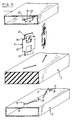
- the composite structure of the invention shown in Figure 1 comprises a first metallic profile 1, a second metallic profile 2, a fireproof layer 3 situated between the first and second metallic profiles 1 and 2.
- Metallic strips or plates 4 extend through the fireproof layer 3 between the first profile 1 and the second profile 2 so as to make a binding between said profiles.
- the end parts 5,6 of the plates 4 are bent so as to push or pull the face 7 of the first profile 1 towards the fireproof layer 3 and the face 8 of the second profile 2 towards the fireproof layer 3.
- the fireproof layer is pressed between the two profiles 1,2, more specifically between the faces 7,8 which contact the fireproof layer.
- the end parts 5,6 are preferably bent so that a part of the plate contact the inner face 9 of the profile which is opposite to the face 7,8 contacting the fireproof layer, and so that the free end of said end parts contacts the inner face of a lateral side 10 of the profile.
- the plates or strips 4 are alternatively located near a lateral face A of the structure and the opposite lateral face B. It means that along its length l, the profiles 1,2 are bound together, first near the face A, then near the face B, near the face A,...
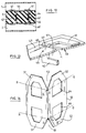
- Figure 2 shows a second embodiment of a structure of the invention.
- the profile 2 has been cut so as to define strips 4 on the upper side 13, side intended to be pushed against the fireproof layer 3.
- the strip 4 has a substantially triangular form and is provided at its end with a rectangular plate 41.
- the strips 4 are bent with respect to said upper side 13 so as to extend in planes X,Y which are parallel to each other and outside the inner space V2 of the profile 2.
- the strips 4 have been cut so that they are distributed alternatively adjacent to one edge 14 of the profile 2 and to the opposite edge 15 of the profile 2.
- the end 41 is introduced in an opening 11 of the profile 1 before being bent (arrow Z) so as to push or pull the lower wall 16 of the profile 1 towards the fireproof material 3.
- the triangular part 19 of the strip has a thickness "e” higher than the width of the openings and than the thickness "e1" of the rectangular plate, or a width "w” higher than the length "l” of the openings 11, whereby said triangular part abuts the face 18 of the profile 1 directed to the fireproof layer 3.
- the face 18 is pushed towards the triangular part 19 and thus towards the fireproof layer 3.
- This system is also suitable for ensuring a specific distance "d" between the profile 1,2.
- FIG. 4 The embodiment shown in Figure 4 is similar to that shown in Figures 2 and 3. However, the strips 4 obtained by bending ends of an open profile 2 are beared by a longitudinal part 25 of the profile 2, which extends towards the profile 1. Said longitudinal part 25 is intended to be engaged into a longitudinal groove 26 of the fireproof layer 3.
- the embodiment of Figure 5 is similar to that shown in Figures 2 and 3.
- the profiles 1 and 2 are open profiles provided adjacent to one lateral edge 27,28 with a plurality of strips 4.
- the strips 4 of the profile 1 are intended, after extending in the fireproof layer 3 to be bent so as to contact the inner surface 9 of the face of the profile 2 directed towards the fireproof layer 3.
- the strips 4 of the profile 1 or 2 are bent so as to contact the part of said face of the other profile 2 or 1, part 29,30 which is not provided with strips 4 intended to be bent so as to contact the inner surface of the face of a profile directed towards the fireproof layer 3.
- the part 29,30 is adjacent to the lateral edge of the profile opposite to the lateral edge 27,28.
- open profile(s) one or two
- Figures 6 to 8 show a further embodiment of a structure of the invention.
- profiles 1,2 are similar and are provided on the face intended to contact the fireproof layer 3, with several openings 11.
- the fireproof layer is provided with a plurality of passages 32 which terminate with a recess 33 on the opposite faces 34,35.
- the elements are strips 4, one end 44 of which is provided with an abutment portion 45, such as a portion obtained by bending the strip 4.
- the abutment portion 45 When the strip 4 is engaged into a passage 32, the abutment portion 45 extends into a recess 33.
- the depth "de” of the recess 33 is preferably such that the abutment portion 45 is underneath the face 34 or 35 of the fireproof layer 3 in contact with a face of a profile 1,2.
- the ends of the strips 4, after passing through an opening of a profile are bent in the inner space V1 or V2 of said profile.
- the binding between the profiles 1,2 is thus obtained by the binding of the fireproof material with a first profile and the binding of said fireproof material with the second profile, said bindings being independent from each other.
- the transfer of heat from one profile towards the other profile and inversely is limited.
- Figure 9 shows an embodiment similar to the embodiment shown in figure 1.
- the profiles 1,2 are provided with slots 11 which extend longitudinally 11a or transversaly 11b with respect to the axial or longitudinal direction P-P of the profile.
- the strips or tongues 4 are metallic square plates 42 provided at two opposite corners with a rectangular end strip or tongue 41 intended to be bent.
- Figure 10 shows an embodiment similar to that of Figure 9, except that the slots 11 extend in a direction making an angle ⁇ , for example comprised between 15 and 75°, preferably of about 45°, with the longitudinal direction P-P of the profile 1,2, and that the square plate 42 are provided with one or more openings 44.
- ⁇ for example comprised between 15 and 75°, preferably of about 45°
- Figure 11 is a view of a structure similar to that shown in Figure 10, except that there is only one row of strips 4 and of slots 11 in the profiles 1,2.
- Said slots 11 make an angle ⁇ comprised between 15 and 45°, preferably 30° with respect to the longitudinal direction P-P of the profiles 1,2.
- the angle ⁇ of the slots is indeed +30° or -30°, i.e. the angle ⁇ of the slots located between two slots with an angle ⁇ of +30° being -30°.
- the strips 4 consist of a central plate 42 provided with two openings 44 and with two legs 41 intended to be bent.
- the openings 44 stretch at least partly within one leg 41.
- Such an embodiment is preferable for limiting the transfer of heat from one profile 1 to the other profile 2 through the strips.
- Figure 13 shows a detail of Figure 11, namely a slot 11. Said slot 11 extends between two wings 45,46 which are bent towards the inner volume defined by a profile.
- the wings 45,46 are advantageously provided with end parts 47 separated from a central part 49 of the wing by means of a cutting 48.
- the central part 49 of the wing has a width "we” corresponding to substantially to the width "f" of the opening 44 so that said central part 49 can be engaged in the opening 44 when the leg 41 is bent.
- the opening 44 extends advantageously partly in the leg 41, so as to facilitate the bending of said leg 41.
- FIG 14 shows a further embodiment of a strip which can be used.
- Said strip consists of a corner profile 50, provided at each end with two legs 51,52 separated from each other by a cutting 53, whereby said legs are suitable for being bent along two different axis Q-Q, R-R.
- the openings 44 can be provided with an isolant material for example before being bent, for example a plastic material.
Landscapes
- Engineering & Computer Science (AREA)
- Architecture (AREA)
- Physics & Mathematics (AREA)
- Electromagnetism (AREA)
- Civil Engineering (AREA)
- Structural Engineering (AREA)
- Building Environments (AREA)
Priority Applications (1)
| Application Number | Priority Date | Filing Date | Title |
|---|---|---|---|
| EP94870144A EP0699809A1 (de) | 1994-08-30 | 1994-08-30 | Feuerfeste Verbundstruktur |
Applications Claiming Priority (1)
| Application Number | Priority Date | Filing Date | Title |
|---|---|---|---|
| EP94870144A EP0699809A1 (de) | 1994-08-30 | 1994-08-30 | Feuerfeste Verbundstruktur |
Publications (1)
| Publication Number | Publication Date |
|---|---|
| EP0699809A1 true EP0699809A1 (de) | 1996-03-06 |
Family
ID=8218669
Family Applications (1)
| Application Number | Title | Priority Date | Filing Date |
|---|---|---|---|
| EP94870144A Withdrawn EP0699809A1 (de) | 1994-08-30 | 1994-08-30 | Feuerfeste Verbundstruktur |
Country Status (1)
| Country | Link |
|---|---|
| EP (1) | EP0699809A1 (de) |
Cited By (3)
| Publication number | Priority date | Publication date | Assignee | Title |
|---|---|---|---|---|
| GB2362897A (en) * | 2000-04-17 | 2001-12-05 | Smyth Plastics Ltd | A panel and a method |
| GB2337776B (en) * | 1998-05-06 | 2002-11-13 | Mss Clean Technology Ltd | Fire resistant ceiling and a ceiling panel for a fire resistant ceiling |
| CN102345332A (zh) * | 2011-10-24 | 2012-02-08 | 沈阳建筑大学 | 装配式防火隔离带 |
Citations (8)
| Publication number | Priority date | Publication date | Assignee | Title |
|---|---|---|---|---|
| DE1784581A1 (de) * | 1968-08-21 | 1971-11-25 | Rigips Baustoffwerke Gmbh | Wandbauelement |
| US4418507A (en) * | 1981-06-30 | 1983-12-06 | Roberts Frank W | Interior wall system |
| DD222147A1 (de) * | 1984-03-15 | 1985-05-08 | Bauakademie Ddr | Verbindungsanker fuer mehrschichtige wandplatten, insbesondere aussenwaende |
| FR2561289A1 (fr) * | 1984-03-16 | 1985-09-20 | Guerin Gabriel | Procede de fixation des plaques de bardage sur une surface support |
| FR2578571A1 (fr) * | 1985-03-05 | 1986-09-12 | Wanner Isofi Isolation | Profile pour panneaux de plafond suspendu des habitations, notamment des bureaux |
| SU1717757A1 (ru) * | 1989-12-05 | 1992-03-07 | Специальное конструкторско-технологическое бюро по промышленности строительной индустрии | Стенова панель |
| GB2269605A (en) * | 1992-08-11 | 1994-02-16 | Omnifire Uk Ltd | Fireproof joint for joining panels end-to-end |
| EP0595777A2 (de) * | 1992-10-22 | 1994-05-04 | Renzo Navarra | Brandschutzplatte mit verbesserter thermischer Beständigkeit |
-
1994
- 1994-08-30 EP EP94870144A patent/EP0699809A1/de not_active Withdrawn
Patent Citations (8)
| Publication number | Priority date | Publication date | Assignee | Title |
|---|---|---|---|---|
| DE1784581A1 (de) * | 1968-08-21 | 1971-11-25 | Rigips Baustoffwerke Gmbh | Wandbauelement |
| US4418507A (en) * | 1981-06-30 | 1983-12-06 | Roberts Frank W | Interior wall system |
| DD222147A1 (de) * | 1984-03-15 | 1985-05-08 | Bauakademie Ddr | Verbindungsanker fuer mehrschichtige wandplatten, insbesondere aussenwaende |
| FR2561289A1 (fr) * | 1984-03-16 | 1985-09-20 | Guerin Gabriel | Procede de fixation des plaques de bardage sur une surface support |
| FR2578571A1 (fr) * | 1985-03-05 | 1986-09-12 | Wanner Isofi Isolation | Profile pour panneaux de plafond suspendu des habitations, notamment des bureaux |
| SU1717757A1 (ru) * | 1989-12-05 | 1992-03-07 | Специальное конструкторско-технологическое бюро по промышленности строительной индустрии | Стенова панель |
| GB2269605A (en) * | 1992-08-11 | 1994-02-16 | Omnifire Uk Ltd | Fireproof joint for joining panels end-to-end |
| EP0595777A2 (de) * | 1992-10-22 | 1994-05-04 | Renzo Navarra | Brandschutzplatte mit verbesserter thermischer Beständigkeit |
Cited By (4)
| Publication number | Priority date | Publication date | Assignee | Title |
|---|---|---|---|---|
| GB2337776B (en) * | 1998-05-06 | 2002-11-13 | Mss Clean Technology Ltd | Fire resistant ceiling and a ceiling panel for a fire resistant ceiling |
| GB2362897A (en) * | 2000-04-17 | 2001-12-05 | Smyth Plastics Ltd | A panel and a method |
| CN102345332A (zh) * | 2011-10-24 | 2012-02-08 | 沈阳建筑大学 | 装配式防火隔离带 |
| CN102345332B (zh) * | 2011-10-24 | 2014-07-02 | 沈阳建筑大学 | 装配式防火隔离带 |
Similar Documents
| Publication | Publication Date | Title |
|---|---|---|
| CA1325705C (en) | Light-transmitting wall panels | |
| CA1158013A (en) | Sandwich panel | |
| EP0585831B1 (de) | Heizer, insbesondere für Küchengeräte | |
| HU224804B1 (en) | Plug connector for hollow sections | |
| EP0006431A1 (de) | Kastenförmige Bautafel aus extrudiertem Kunststoff | |
| DE2825118A1 (de) | Vorgefertigtes wandelement | |
| DE2916667C2 (de) | Vorrichtung zum Einsetzen von Füllelementen aus Isolierfasermaterial | |
| US3386221A (en) | Lightweight panel | |
| DE2165353A1 (de) | Verbindungssystem | |
| EP0699809A1 (de) | Feuerfeste Verbundstruktur | |
| EP1660749A1 (de) | Profil und verfahren zum herstellen eines profils | |
| EP0026605B1 (de) | Bauplatten | |
| EP0004006B1 (de) | Geradverbinder, insbesondere aus Kunststoff, für hohle Abstandsprofile eines Mehrscheibenisolierglases | |
| EP3221599B1 (de) | Steckverbinder und steckverbindung | |
| DE1658468C3 (de) | Elastische Fugeneinlage, insbesondere in Straßenbefestigungen | |
| CH671989A5 (en) | Multilayer wall panel for military applications - has structure enclosed by profiled frame electrically coupled to central metal sheet | |
| EP1018316B1 (de) | Rost zur Bildung von Laufmatten, Fussabstreifern oder dergleichen | |
| US5642564A (en) | Method of joining stiff plate profile members into broad lamellae or panels | |
| CA1263212A (en) | Insulated metal skinned panel assembly | |
| DE4436808A1 (de) | Verbindungselement | |
| EP2535657A1 (de) | Modulares Fluidleitungsbauteil | |
| GB2121848A (en) | Wall studs and connectors therefor | |
| FI60945C (fi) | Fjaederpacke foer elektromagnetiskt relae | |
| GB2118993A (en) | Joint for modular building panels | |
| KR890002614A (ko) | 전자레인지의 가열상자 |
Legal Events
| Date | Code | Title | Description |
|---|---|---|---|
| PUAI | Public reference made under article 153(3) epc to a published international application that has entered the european phase |
Free format text: ORIGINAL CODE: 0009012 |
|
| AK | Designated contracting states |
Kind code of ref document: A1 Designated state(s): AT BE DE FR |
|
| 17P | Request for examination filed |
Effective date: 19960723 |
|
| STAA | Information on the status of an ep patent application or granted ep patent |
Free format text: STATUS: THE APPLICATION IS DEEMED TO BE WITHDRAWN |
|
| 18D | Application deemed to be withdrawn |
Effective date: 19980303 |