EP0699862A2 - Procédé pour la rénovation de canalisations, notamment pour canalisations sanitaires - Google Patents
Procédé pour la rénovation de canalisations, notamment pour canalisations sanitaires Download PDFInfo
- Publication number
- EP0699862A2 EP0699862A2 EP95113829A EP95113829A EP0699862A2 EP 0699862 A2 EP0699862 A2 EP 0699862A2 EP 95113829 A EP95113829 A EP 95113829A EP 95113829 A EP95113829 A EP 95113829A EP 0699862 A2 EP0699862 A2 EP 0699862A2
- Authority
- EP
- European Patent Office
- Prior art keywords
- pipeline
- application body
- movement
- section
- pipelines
- Prior art date
- Legal status (The legal status is an assumption and is not a legal conclusion. Google has not performed a legal analysis and makes no representation as to the accuracy of the status listed.)
- Granted
Links
- 238000000034 method Methods 0.000 title claims abstract description 29
- 239000011248 coating agent Substances 0.000 claims abstract description 26
- 239000007788 liquid Substances 0.000 claims abstract description 15
- 230000005484 gravity Effects 0.000 claims abstract description 12
- 239000004850 liquid epoxy resins (LERs) Substances 0.000 claims abstract description 5
- 239000006260 foam Substances 0.000 claims description 7
- 238000004140 cleaning Methods 0.000 claims description 4
- 238000000576 coating method Methods 0.000 abstract description 11
- 239000012530 fluid Substances 0.000 abstract 2
- 239000006261 foam material Substances 0.000 abstract 1
- 238000009418 renovation Methods 0.000 description 11
- 210000003127 knee Anatomy 0.000 description 3
- XLYOFNOQVPJJNP-UHFFFAOYSA-N water Substances O XLYOFNOQVPJJNP-UHFFFAOYSA-N 0.000 description 3
- JEIPFZHSYJVQDO-UHFFFAOYSA-N iron(III) oxide Inorganic materials O=[Fe]O[Fe]=O JEIPFZHSYJVQDO-UHFFFAOYSA-N 0.000 description 2
- 239000002245 particle Substances 0.000 description 2
- 230000000717 retained effect Effects 0.000 description 2
- 239000004071 soot Substances 0.000 description 2
- 230000007704 transition Effects 0.000 description 2
- 241001674044 Blattodea Species 0.000 description 1
- 230000006978 adaptation Effects 0.000 description 1
- 230000002411 adverse Effects 0.000 description 1
- 230000006735 deficit Effects 0.000 description 1
- 239000003822 epoxy resin Substances 0.000 description 1
- 230000002349 favourable effect Effects 0.000 description 1
- 239000000463 material Substances 0.000 description 1
- 229920000647 polyepoxide Polymers 0.000 description 1
- 238000009419 refurbishment Methods 0.000 description 1
- 230000003319 supportive effect Effects 0.000 description 1
Images

Classifications
-
- F—MECHANICAL ENGINEERING; LIGHTING; HEATING; WEAPONS; BLASTING
- F16—ENGINEERING ELEMENTS AND UNITS; GENERAL MEASURES FOR PRODUCING AND MAINTAINING EFFECTIVE FUNCTIONING OF MACHINES OR INSTALLATIONS; THERMAL INSULATION IN GENERAL
- F16L—PIPES; JOINTS OR FITTINGS FOR PIPES; SUPPORTS FOR PIPES, CABLES OR PROTECTIVE TUBING; MEANS FOR THERMAL INSULATION IN GENERAL
- F16L55/00—Devices or appurtenances for use in, or in connection with, pipes or pipe systems
- F16L55/16—Devices for covering leaks in pipes or hoses, e.g. hose-menders
- F16L55/162—Devices for covering leaks in pipes or hoses, e.g. hose-menders from inside the pipe
- F16L55/164—Devices for covering leaks in pipes or hoses, e.g. hose-menders from inside the pipe a sealing fluid being introduced in the pipe
Definitions
- the invention relates to a method for the rehabilitation of pipelines, in particular downpipes.
- the invention is therefore based on the object of making available such a method for the rehabilitation of pipelines, in particular downpipes, by means of which replacement of the pipelines becomes unnecessary.
- the applicator body can be moved through the pipeline without using any additional aids, using gravity. With the applicator body, the liquid column also moves down the tube, thereby lining the inner wall of the pipeline treated in this way with a layer formed from the coating agent. It is necessary that the application body completely fills the clear cross-section of the pipeline, otherwise the liquid column cannot be formed. Through the use of gravity it is also achieved that the application body passes through the pipeline to be renovated at low speed, so that it can be easily removed from the pipe at the designated location at the lower end of the pipe and not by too high a speed Pipeline damaged.
- a foam body is preferably used as the application body.
- Such a foam body is sufficiently compressible for the requirements placed on application bodies when renovating pipelines that are downpipes. Since the foam body preferably has a greater extent in the direction of movement than perpendicular to the direction of movement and particularly preferably has an essentially oval cross section, the friction which arises between the inner wall of the pipeline and the application body enables the application body to slide slowly through the pipeline, the liquid column nevertheless being sufficient can be kept large, in particular in order to ensure that sufficient coating agent can run into the branch pipe (s) leading into the pipe branching into the pipeline.
- a liquid epoxy resin is used as the coating agent. These are usually characterized by the fact that they are self-curing.
- the application body is at least partially moved through the pipeline in addition to the gravity acting by means of a pulling and / or pushing device.
- the pulling device which can be, for example, a rope or a chain, is fastened to the application body in a manner known per se.
- the tensile force acting on the application body has a supportive effect on the movement of the application body through the pipeline, utilizing gravity.
- a push rod is preferably used as the pushing device, which has the advantage that it does not have to be attached to the applicator body.
- a holding device can also be provided, by means of which the movement of the application body through the pipeline is stopped for a defined period of time. This can be of advantage if the pipeline has strong cracks in order to ensure that these cracks are filled as completely as possible with the coating agent. In addition, such a stopping of the movement of the application body can be advantageous when branches are reached, since the coating agent then has sufficient time to run into the corresponding branch pipe.
- the application body is moved through the pipeline repeatedly, preferably twice, particularly preferably three or four times.
- the layer thickness with which the inner tube wall is lined can be adjusted individually and depending on the coating agent used.
- pipes which consist of sections of different diameters can be renovated.
- the application body is dimensioned so that it completely the clear cross-section of that section of the pipeline fills out, which has the largest diameter. Because of the compressibility of the application body, it is then ensured that the application body can be compressed during the transition to the section with a smaller diameter and can thus also be carried out through the section with the smaller diameter. This applies accordingly if a section with a smaller diameter is to be renovated first, which is followed by a section with a larger diameter. In this case, the application body can then expand, whereby it must always be ensured that the application body is dimensioned such that it completely fills the clear cross section of the section with the largest diameter.
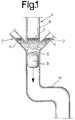
- FIG. 1 shows a pipeline 1 in the form of a downpipe, as can be found in particular in buildings.
- Two branches 2 open into this pipeline 1.
- it can first be cleaned and then provided with a deep foundation. Any deep dirt, rust or soot particles that may be present are bound and retained by the treatment with deep ground, which could otherwise prevent the coating agent from adhering to the inner wall of the pipeline 1.
- the subsequent coating is not adversely affected by the treatment with deep underground, because it penetrates completely into the underground.
- an application body 3 is preferably introduced into the pipeline 1 via the vent, which is common in downpipes and is not shown in the drawing.
- a foam body is preferably used as the application body 3, which has a greater extent in the direction of movement, which is indicated by an arrow in the figures, than perpendicular to the direction of movement and preferably has an essentially oval cross section.
- the material for forming the application body 3 is not limited to foam.
- any configuration of the application body that guarantees its compressibility can be considered.
- the application body 3 completely fills the clear cross section of the pipeline 1.
- a low-viscosity coating agent, preferably a liquid, self-curing epoxy resin, in the form of a liquid column 7 is now applied to the boundary 5 of the application body 3 opposite the direction of movement.
- the height of the liquid column 7 is just chosen so that, using gravity, the friction of the application body 3 on the inner pipe wall is overcome so far that the application body 3 is moved through the pipe 1 at the desired speed.
- the branches 2 opening into them are fundamentally particularly problematic, since these branches 2 should also be refurbished at least in a finite section above the confluence with the pipeline 1 by applying a coating.
- the partial refurbishment of the branches 2 is made possible in a particularly favorable and simple manner by the method according to the invention in that when the application body 3 has passed the junction of the branch 2 into the pipeline, the coating agent forming the liquid column 7 rises into this branch 2, around with further downward movement of the application body 3 together with the liquid column, which is still in the pipeline 1, to sink and thus flow out of the branch 2. What remains is both a coating 9 of the inner wall of the pipeline 1 and a coating 9 'of the inner wall of each of the branches 2.
- the size of the partial section coated in each branch 2 depends on the height of the liquid column 7 in the branch 2.
- the application body 3 according to the invention can, however, be carried out very simply by means of these supports 11, which are designed as knees, since on the one hand it is moved downward by the liquid column 7 using gravity and, on the other hand, due to its compressibility, it can adapt to the respectively curved section of the support 11 .
- the application body 3 is either connected at its limit in the direction of movement in a manner known per se to a pulling device, for example a rope or a chain, or at the limit 5 of the order body 3 opposite the direction of movement attacks a pushing device in the form of a push rod, as a result of which the application body 3 is moved through the pipeline 1 in addition to the acting gravity.
- a pulling device for example a rope or a chain
- a pushing device in the form of a push rod
- the movement of the application body 3 through the pipeline 1 can be stopped for a defined period of time by means of a holding device (not shown in the drawing).
- the holding device used can be designed in exactly the same way as the pulling device described above, with the difference that it is then attached to the boundary 5 of the application body 3 opposite the direction of movement. Then the same device can serve as a holding device and another time as a pulling device.
- a rod as a holding device, which is inserted into the pipeline from below, for example via a cleaning opening.
- liquid epoxy resins can be used as the liquid epoxy resin which is used as a coating agent in the renovation according to the invention.
- the specialist carrying out the renovation of the respective pipeline 1 has the possibility of varying the repeated coating processes between coating processes solely by using gravity and those in which a pulling, pushing and / or holding device is used at the same time, depending on as the pipeline to be renovated 1 required. It has proven to be advantageous that the last coating pass is carried out without a pulling, pushing and / or holding device.
- a particular application of the renovation method according to the invention is in the renovation of pipelines 1, which consist of sections of different diameters.
- the procedure is in the manner described above, care being taken that the application body 3 is dimensioned such that it completely fills the clear cross section of the section of the pipeline 1 which has the largest diameter. Because of the compressibility of the application body 1, it is then ensured that the application body 1 can be compressed during the transition to the section with the smaller diameter and can thus also be carried out through the section with the smaller diameter. This applies accordingly if a section with a smaller diameter is to be renovated first, which is followed by a section with a larger diameter. In this case, the application body 3 can then expand, it again having to be dimensioned such that it still completely fills the clear cross section of the section with the largest diameter.
- Another application of the method according to the invention is in the area of food-producing companies or catering establishments. In these areas, ensuring freedom from vermin is imperative on the one hand, and problematic on the other. It is possible that older pipelines in particular are not in need of renovation per se, but have a rough inner wall. Bugs, in particular the cockroaches that occur frequently in the food sector, are able to pass through such rough inner walls of pipelines 1 and are therefore difficult to control. After applying the renovation method according to the invention, however, the inner wall becomes essentially smooth guaranteed where the said vermin can no longer move.
- the renovation method according to the invention is not limited to use in downpipes, but can also be used, for example, in inclined basic pipes. There should only be such a gradient of the respective pipeline 1, which enables the use of gravity without requiring an excessive height of the liquid column, which is no longer economical due to the amount of coating agent then required.
- the method according to the invention is also not limited to essentially round pipes, but can also be used for other pipes with a non-round cross section, for example chimneys.
Landscapes
- Engineering & Computer Science (AREA)
- General Engineering & Computer Science (AREA)
- Mechanical Engineering (AREA)
- Application Of Or Painting With Fluid Materials (AREA)
- Investigating Or Analyzing Materials By The Use Of Ultrasonic Waves (AREA)
- Lining Or Joining Of Plastics Or The Like (AREA)
- Pipeline Systems (AREA)
- Electric Cable Installation (AREA)
- Reverberation, Karaoke And Other Acoustics (AREA)
Applications Claiming Priority (2)
| Application Number | Priority Date | Filing Date | Title |
|---|---|---|---|
| DE4431155 | 1994-09-02 | ||
| DE4431155A DE4431155C1 (de) | 1994-09-02 | 1994-09-02 | Verfahren zur Sanierung von Rohrleitungen, insbesondere Falleitungen |
Publications (3)
| Publication Number | Publication Date |
|---|---|
| EP0699862A2 true EP0699862A2 (fr) | 1996-03-06 |
| EP0699862A3 EP0699862A3 (fr) | 1996-08-28 |
| EP0699862B1 EP0699862B1 (fr) | 2000-01-12 |
Family
ID=6527177
Family Applications (1)
| Application Number | Title | Priority Date | Filing Date |
|---|---|---|---|
| EP95113829A Expired - Lifetime EP0699862B1 (fr) | 1994-09-02 | 1995-09-04 | Procédé pour la rénovation de canalisations penchées |
Country Status (3)
| Country | Link |
|---|---|
| EP (1) | EP0699862B1 (fr) |
| AT (1) | ATE188764T1 (fr) |
| DE (2) | DE4431155C1 (fr) |
Cited By (2)
| Publication number | Priority date | Publication date | Assignee | Title |
|---|---|---|---|---|
| US7635008B2 (en) | 2006-07-18 | 2009-12-22 | Gaphog International, A Utah Llc | Flow restricting device having self-forming conduits |
| US7650911B2 (en) | 2006-07-18 | 2010-01-26 | Gaphog International, A Utah Llc | Method for restricting fluid flow in a passageway |
Families Citing this family (2)
| Publication number | Priority date | Publication date | Assignee | Title |
|---|---|---|---|---|
| DE19635802A1 (de) * | 1996-09-04 | 1998-03-05 | Jt Elektronik Gmbh | Verfahren und Mittel zur Abdichtung von Abflußrohren im Hausabwasserrohrnetz |
| DE19831058C2 (de) * | 1998-07-13 | 2000-11-30 | Preussag Spezialtiefbau Gmbh N | Verfahren zum Behandeln der Innenseite von Hohlräumen mit einer Flüssigkeit und Vorrichtung zur Durchführung des Verfahrens |
Family Cites Families (4)
| Publication number | Priority date | Publication date | Assignee | Title |
|---|---|---|---|---|
| DE3204386C2 (de) * | 1982-02-09 | 1985-06-27 | Osaka Gas Co. Ltd., Osaka | Verfahren zum Instandsetzen eines unterirdischen Rohres |
| IE832804L (en) * | 1983-11-29 | 1985-05-29 | Attwell Ronald Leslie | Applying a lining to a conduit such as a chimney flue |
| DE4026116A1 (de) * | 1990-08-17 | 1992-02-20 | Ruediger Schmidt | Verfahren und vorrichtung zum sanieren von rohren |
| GB9301767D0 (en) * | 1993-01-29 | 1993-03-17 | Amec Utilities Ltd | A method of lining pipe |
-
1994
- 1994-09-02 DE DE4431155A patent/DE4431155C1/de not_active Expired - Fee Related
-
1995
- 1995-09-04 EP EP95113829A patent/EP0699862B1/fr not_active Expired - Lifetime
- 1995-09-04 AT AT95113829T patent/ATE188764T1/de not_active IP Right Cessation
- 1995-09-04 DE DE59507597T patent/DE59507597D1/de not_active Expired - Fee Related
Cited By (2)
| Publication number | Priority date | Publication date | Assignee | Title |
|---|---|---|---|---|
| US7635008B2 (en) | 2006-07-18 | 2009-12-22 | Gaphog International, A Utah Llc | Flow restricting device having self-forming conduits |
| US7650911B2 (en) | 2006-07-18 | 2010-01-26 | Gaphog International, A Utah Llc | Method for restricting fluid flow in a passageway |
Also Published As
| Publication number | Publication date |
|---|---|
| ATE188764T1 (de) | 2000-01-15 |
| DE4431155C1 (de) | 1996-04-04 |
| EP0699862B1 (fr) | 2000-01-12 |
| DE59507597D1 (de) | 2000-02-17 |
| EP0699862A3 (fr) | 1996-08-28 |
Similar Documents
| Publication | Publication Date | Title |
|---|---|---|
| EP0777551B1 (fr) | Procede permettant de renover des canalisations | |
| DE69522464T2 (de) | Verfahren zur Innenbeschichtung eines Rohres | |
| DE2709112B2 (de) | Vorrichtung und Verfahren zum Einspritzen von Schaum in eine zu reinigende Rohrleitung | |
| DE2629214A1 (de) | Verfahren und mittel zum auskleiden von rohrleitungen | |
| EP1001206B1 (fr) | Méthode et appareil pour la rénovation d'un vieil élément tubulaire enterré | |
| DE69631652T2 (de) | Unterdruck-abwasseranlage | |
| DE10159575A1 (de) | Wanddurchführung für Leitungen | |
| DE3732694C2 (de) | Verfahren zum Auskleiden von Kanälen | |
| DE4431155C1 (de) | Verfahren zur Sanierung von Rohrleitungen, insbesondere Falleitungen | |
| DE60310940T2 (de) | Verfahren zum abdichten und/oder wiederinstandsetzen von rohren | |
| DE9109334U1 (de) | Vorrichtung zum Auskleiden von Rohrleitungen mit einer Innenbeschichtung | |
| DE10323298B4 (de) | Verfahren zur Sanierung von inkrustierten Wasserrohrleitungen | |
| DE69727295T2 (de) | Vorrichtung für die Reparatur eines Rohres und ein Verfahren zur Benutzung derselben | |
| DE4435744C2 (de) | Verfahren zum Reinigen und Freilegen längenmäßig begrenzter Abschnitte von Litzen aus Stahldrähten | |
| DE29814270U1 (de) | Anordnung von unterirdisch verlegten Kabeln, Leitungen und/oder Leerrohren hierfür | |
| DE69226679T2 (de) | Vorrichtung zum Entfernen eines Zementmantels aus einer Knochenhöhlung | |
| DE10358253B4 (de) | Verfahren zur Sanierung von inkrustierten Wasserrohrleitungen mit mehreren Leitungsabschnitten | |
| DE3934980A1 (de) | Verfahren und vorrichtung zum sanieren eines in der erde verlegten kanalrohres oder dgl. | |
| DE10160371B4 (de) | Verfahren und Vorrichtung zur Reinigung von Rohrleitungen | |
| CH683205A5 (de) | Bauelementensatz zum Abdichten von Kanälen. | |
| DE3722622C1 (en) | Process for repairing a buried sewer pipe | |
| DE19911591C2 (de) | Verfahren zur Spülung und Reinigung von Brauchwassersystemen, Brauchwasserleitungen, Heizungssystemen o. dgl. | |
| DE3124613A1 (de) | Verfahren zum auskleiden einer rohrleitung mit einer flexiblen, zylinderfoermigen folie | |
| DE19633932C2 (de) | Verfahren zum Sanieren von wenigstens teilweise unter der Oberfläche verlegten Rohrleitungen | |
| EP3614032B1 (fr) | Dispositif et procédé d'assainissement d'une section de tuyau d'un système de tuyauterie |
Legal Events
| Date | Code | Title | Description |
|---|---|---|---|
| PUAI | Public reference made under article 153(3) epc to a published international application that has entered the european phase |
Free format text: ORIGINAL CODE: 0009012 |
|
| AK | Designated contracting states |
Kind code of ref document: A2 Designated state(s): AT BE CH DE DK FR GB IT LI LU MC NL |
|
| PUAL | Search report despatched |
Free format text: ORIGINAL CODE: 0009013 |
|
| AK | Designated contracting states |
Kind code of ref document: A3 Designated state(s): AT BE CH DE DK FR GB IT LI LU MC NL |
|
| 17P | Request for examination filed |
Effective date: 19960724 |
|
| 17Q | First examination report despatched |
Effective date: 19980508 |
|
| GRAG | Despatch of communication of intention to grant |
Free format text: ORIGINAL CODE: EPIDOS AGRA |
|
| GRAG | Despatch of communication of intention to grant |
Free format text: ORIGINAL CODE: EPIDOS AGRA |
|
| GRAH | Despatch of communication of intention to grant a patent |
Free format text: ORIGINAL CODE: EPIDOS IGRA |
|
| RAP1 | Party data changed (applicant data changed or rights of an application transferred) |
Owner name: ROSATEC FORSCHUNGS- UND ENTWICKLUNGSGESELLSCHAFT F |
|
| GRAH | Despatch of communication of intention to grant a patent |
Free format text: ORIGINAL CODE: EPIDOS IGRA |
|
| GRAA | (expected) grant |
Free format text: ORIGINAL CODE: 0009210 |
|
| AK | Designated contracting states |
Kind code of ref document: B1 Designated state(s): AT BE CH DE DK FR GB IT LI LU MC NL |
|
| PG25 | Lapsed in a contracting state [announced via postgrant information from national office to epo] |
Ref country code: NL Free format text: LAPSE BECAUSE OF FAILURE TO SUBMIT A TRANSLATION OF THE DESCRIPTION OR TO PAY THE FEE WITHIN THE PRESCRIBED TIME-LIMIT Effective date: 20000112 Ref country code: IT Free format text: LAPSE BECAUSE OF FAILURE TO SUBMIT A TRANSLATION OF THE DESCRIPTION OR TO PAY THE FEE WITHIN THE PRE;WARNING: LAPSES OF ITALIAN PATENTS WITH EFFECTIVE DATE BEFORE 2007 MAY HAVE OCCURRED AT ANY TIME BEFORE 2007. THE CORRECT EFFECTIVE DATE MAY BE DIFFERENT FROM THE ONE RECORDED.SCRIBED TIME-LIMIT Effective date: 20000112 Ref country code: GB Free format text: LAPSE BECAUSE OF FAILURE TO SUBMIT A TRANSLATION OF THE DESCRIPTION OR TO PAY THE FEE WITHIN THE PRESCRIBED TIME-LIMIT Effective date: 20000112 Ref country code: FR Free format text: LAPSE BECAUSE OF FAILURE TO SUBMIT A TRANSLATION OF THE DESCRIPTION OR TO PAY THE FEE WITHIN THE PRESCRIBED TIME-LIMIT Effective date: 20000112 |
|
| REF | Corresponds to: |
Ref document number: 188764 Country of ref document: AT Date of ref document: 20000115 Kind code of ref document: T |
|
| REG | Reference to a national code |
Ref country code: CH Ref legal event code: EP |
|
| REF | Corresponds to: |
Ref document number: 59507597 Country of ref document: DE Date of ref document: 20000217 |
|
| REG | Reference to a national code |
Ref country code: CH Ref legal event code: NV Representative=s name: SCHMAUDER & PARTNER AG PATENTANWALTSBUERO |
|
| PG25 | Lapsed in a contracting state [announced via postgrant information from national office to epo] |
Ref country code: DK Free format text: LAPSE BECAUSE OF FAILURE TO SUBMIT A TRANSLATION OF THE DESCRIPTION OR TO PAY THE FEE WITHIN THE PRESCRIBED TIME-LIMIT Effective date: 20000412 |
|
| NLV1 | Nl: lapsed or annulled due to failure to fulfill the requirements of art. 29p and 29m of the patents act | ||
| EN | Fr: translation not filed | ||
| GBV | Gb: ep patent (uk) treated as always having been void in accordance with gb section 77(7)/1977 [no translation filed] |
Effective date: 20000112 |
|
| PG25 | Lapsed in a contracting state [announced via postgrant information from national office to epo] |
Ref country code: LU Free format text: LAPSE BECAUSE OF NON-PAYMENT OF DUE FEES Effective date: 20000904 Ref country code: AT Free format text: LAPSE BECAUSE OF NON-PAYMENT OF DUE FEES Effective date: 20000904 |
|
| PG25 | Lapsed in a contracting state [announced via postgrant information from national office to epo] |
Ref country code: MC Free format text: THE PATENT HAS BEEN ANNULLED BY A DECISION OF A NATIONAL AUTHORITY Effective date: 20000930 Ref country code: BE Free format text: LAPSE BECAUSE OF NON-PAYMENT OF DUE FEES Effective date: 20000930 |
|
| PLBE | No opposition filed within time limit |
Free format text: ORIGINAL CODE: 0009261 |
|
| STAA | Information on the status of an ep patent application or granted ep patent |
Free format text: STATUS: NO OPPOSITION FILED WITHIN TIME LIMIT |
|
| 26N | No opposition filed | ||
| BERE | Be: lapsed |
Owner name: ROSATEC FORSCHUNGS- UND ENTWICKLUNGSG.- FUR ROHRS Effective date: 20000930 |
|
| REG | Reference to a national code |
Ref country code: CH Ref legal event code: NV Representative=s name: DR. REGINE WUESTEFELD, PATENTANWAELTIN |
|
| PGFP | Annual fee paid to national office [announced via postgrant information from national office to epo] |
Ref country code: CH Payment date: 20050919 Year of fee payment: 11 |
|
| PGFP | Annual fee paid to national office [announced via postgrant information from national office to epo] |
Ref country code: DE Payment date: 20050922 Year of fee payment: 11 |
|
| PG25 | Lapsed in a contracting state [announced via postgrant information from national office to epo] |
Ref country code: LI Free format text: LAPSE BECAUSE OF NON-PAYMENT OF DUE FEES Effective date: 20060930 Ref country code: CH Free format text: LAPSE BECAUSE OF NON-PAYMENT OF DUE FEES Effective date: 20060930 |
|
| PG25 | Lapsed in a contracting state [announced via postgrant information from national office to epo] |
Ref country code: DE Free format text: LAPSE BECAUSE OF NON-PAYMENT OF DUE FEES Effective date: 20070403 |
|
| REG | Reference to a national code |
Ref country code: CH Ref legal event code: PL |