EP0699993B1 - Verfahren und Vorrichtung zur Anzeige der Ränder von verbundenen Datenuntergruppen - Google Patents
Verfahren und Vorrichtung zur Anzeige der Ränder von verbundenen Datenuntergruppen Download PDFInfo
- Publication number
- EP0699993B1 EP0699993B1 EP95480113A EP95480113A EP0699993B1 EP 0699993 B1 EP0699993 B1 EP 0699993B1 EP 95480113 A EP95480113 A EP 95480113A EP 95480113 A EP95480113 A EP 95480113A EP 0699993 B1 EP0699993 B1 EP 0699993B1
- Authority
- EP
- European Patent Office
- Prior art keywords
- data
- subset
- terminus
- indicates
- displaying
- Prior art date
- Legal status (The legal status is an assumption and is not a legal conclusion. Google has not performed a legal analysis and makes no representation as to the accuracy of the status listed.)
- Expired - Lifetime
Links
Images




Classifications
-
- G—PHYSICS
- G06—COMPUTING OR CALCULATING; COUNTING
- G06F—ELECTRIC DIGITAL DATA PROCESSING
- G06F3/00—Input arrangements for transferring data to be processed into a form capable of being handled by the computer; Output arrangements for transferring data from processing unit to output unit, e.g. interface arrangements
- G06F3/01—Input arrangements or combined input and output arrangements for interaction between user and computer
- G06F3/048—Interaction techniques based on graphical user interfaces [GUI]
- G06F3/0487—Interaction techniques based on graphical user interfaces [GUI] using specific features provided by the input device, e.g. functions controlled by the rotation of a mouse with dual sensing arrangements, or of the nature of the input device, e.g. tap gestures based on pressure sensed by a digitiser
- G06F3/0489—Interaction techniques based on graphical user interfaces [GUI] using specific features provided by the input device, e.g. functions controlled by the rotation of a mouse with dual sensing arrangements, or of the nature of the input device, e.g. tap gestures based on pressure sensed by a digitiser using dedicated keyboard keys or combinations thereof
-
- G—PHYSICS
- G06—COMPUTING OR CALCULATING; COUNTING
- G06F—ELECTRIC DIGITAL DATA PROCESSING
- G06F3/00—Input arrangements for transferring data to be processed into a form capable of being handled by the computer; Output arrangements for transferring data from processing unit to output unit, e.g. interface arrangements
- G06F3/01—Input arrangements or combined input and output arrangements for interaction between user and computer
- G06F3/048—Interaction techniques based on graphical user interfaces [GUI]
- G06F3/0484—Interaction techniques based on graphical user interfaces [GUI] for the control of specific functions or operations, e.g. selecting or manipulating an object, an image or a displayed text element, setting a parameter value or selecting a range
- G06F3/0485—Scrolling or panning
-
- G—PHYSICS
- G06—COMPUTING OR CALCULATING; COUNTING
- G06F—ELECTRIC DIGITAL DATA PROCESSING
- G06F3/00—Input arrangements for transferring data to be processed into a form capable of being handled by the computer; Output arrangements for transferring data from processing unit to output unit, e.g. interface arrangements
- G06F3/01—Input arrangements or combined input and output arrangements for interaction between user and computer
- G06F3/048—Interaction techniques based on graphical user interfaces [GUI]
- G06F3/0484—Interaction techniques based on graphical user interfaces [GUI] for the control of specific functions or operations, e.g. selecting or manipulating an object, an image or a displayed text element, setting a parameter value or selecting a range
- G06F3/0485—Scrolling or panning
- G06F3/04855—Interaction with scrollbars
Definitions
- the present invention relates in general to improved data processing systems and in particular to improvements in the presentation of data within a data processing system. Still more particularly, the present invention relates to improvements in the display of data within a display window in a data processing system.
- Data may be manipulated in many ways in a modern state-of-the-art data processing system including: data accessing; data encoding data communications; data compression; data conversion; data entry; data exchange; data linking; data locking; data mapping; data modeling; data processing; data recording; data sorting; and data transferring.
- data accessing data encoding data communications
- data compression data conversion
- data entry data entry
- data exchange data linking
- data locking data locking
- data mapping data modeling
- data processing data recording
- data sorting data transferring.
- the large amounts of data which are available to the user of a modern state-of-the-art data processing system often become overwhelming in magnitude and complexity.
- GUI graphical user interface
- the common user access (CUA) user interface is an example of one such GUI.
- Common user access is a trademark of the International Business Machines Corporation.
- the CUA user interface is often employed to organize and present large amounts of data to a user in a graphical and intuitive manner. More information on CUA interfaces may be found in systems application architecture common user access guide to user interface design, SC34-4289-00 available from International Business Machines Corporation.
- a window such as window 2 in Figure 1 is employed to display lists or collections of data, such as items X to X+9 in subsets A to D.
- indication of a subset of these data collections to the user is a requirement because of some significant distinguishing characteristic of the given subset's members.
- Standard and state-of-the-art methods for indicating subsets already exist. When the subset cannot be completely displayed on the display device, existing methods provide a complex indication to the user about the extent of the subset.
- Patent application EP-A-0 509 160 already discloses such a method.
- the present invention provides a method and system for indicating boundaries of data subsets that are displayed in a display window in a data processing system.
- Data having data subsets are displayed within a display window with a selected data subset being visible within the window.
- the selected data subset has an upper and lower boundary.
- a marker is displayed in association with the display window in response to a selected data subset within the plurality of data subsets being displayed within the display window.
- the marker has two terminuses, an upper terminus and a lower terminus. The location of the upper terminus indicates an upper boundary of the selected data subset and the location of the lower terminus indicates the lower boundary of the selected data subset.
- An absence of one of the two terminuses intuitively indicates, to a user, a presence of additional undisplayed data within the selected data set that is not displayed within the display window.
- An absence of the upper terminus indicates that the upper boundary of the selected data subset is not visible, and an absence of the lower terminus indicates that the lower boundary of the selected data subset is not visible.
- the slope of the sides of the marker provide an indication of how far away the absent terminus is from the visible portion of the marker.
- FIG. 1 a data processing system, personal computer system 10, in which the present invention can be employed is depicted.
- personal computer system 10 comprises a number of components, which are interconnected together. More particularly, a system unit 12 is coupled to and can drive an optional monitor 14 (such as a conventional video display).
- an optional monitor 14 such as a conventional video display
- a system unit 12 also can be optionally coupled to input devices such as a PC keyboard 16 or a mouse 18.
- Mouse 18 includes right and left buttons (not shown).
- the left button is generally employed as the main selector button and alternatively is referred to as the first mouse button or mouse button 1.
- the right button is typically employed to select auxiliary functions as explained later.
- the right mouse button is alternatively referred to as the second mouse button or mouse button 2.
- An optional output device, such as a printer 20, also can be connected to the system unit 12.
- system unit 12 may include one or more mass storage devices such as the diskette drive 22.
- system unit 12 responds to input devices, such as PC keyboard 16, the mouse 18, or local area networking interfaces. Additionally, input/output (I/O) devices, such as floppy diskette drive 22, display 14, printer 20, and local area network communication system are connected to system unit 12 in a manner well known. Of course, those skilled in the art are aware that other conventional components also can be connected to the system unit 12 for interaction therewith.
- personal computer system 10 includes a system processor that is interconnected to a random access memory (RAM), a read only memory (ROM), and a plurality of I/O devices.
- RAM random access memory
- ROM read only memory
- personal computer system 10 can be designed to give independent computing power to a small group of users as a server or a single user and is inexpensively priced for purchase by individuals or small businesses.
- the system processor functions under an operating system, such as IBM's OS/2 operating system or DOS.
- OS/2 is a registered trademark of International Business Machines Corporation.
- This type of operating system includes a Basic Input/Output System (BIOS) interface between the I/O devices and the operating system.
- BIOS which can be stored in a ROM on a motherboard or planar, includes diagnostic routines which are contained in a power on self test section referred to as POST.
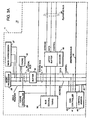
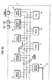
- FIG. 2 there is shown a block diagram of personal computer system 10 illustrating the various components of personal computer system 10 in accordance with the present invention.
- Figure 2 further illustrates components of planar 11 and the connection of planar 11 to I/O slots 46a-46d and other hardware of personal computer system 10.
- CPU central processing unit
- RAM volatile random access memory
- Pentium microprocessor is sold by Intel Corporation. "Pentium” is a trademark of Intel Corporation.
- system processor could be an Intel 80286, 80386, or 80486 microprocessor. These particular microprocessors can operate in a real addressing mode or a protected addressing mode.
- Each mode provides an addressing scheme for accessing different areas of the microprocessor's memory.
- CPU local bus 24 (comprising data, address and control components) provides for the connection of CPU 26, an optional math coprocessor 27, a cache controller 28, and a cache memory 30. Also coupled on CPU local bus 24 is a buffer 32. Buffer 32 is itself connected to a slower speed (compared to the CPU local bus) system bus 34, also comprising address, data and control components.
- System bus 34 extends between buffer 32 and a further buffer 36.
- System bus 34 is further connected to a bus control and timing unit 38 and a Direct Memory Access (DMA) unit 40.
- DMA unit 40 is comprised of a central arbitration unit 48 and a DMA controller 41.
- Buffer 36 provides an interface between the system bus 34 and an optional feature bus such as the Micro Channel bus 44. "Micro Channel” is a registered trademark of International Business Machines Corporation.
- Connected to bus 44 are a plurality of I/O slots 46a-46d for receiving Micro Channel adapter cards which may be further connected to an I/O device or memory.
- I/O slot 46a has a hard disk drive connected to it; I/O slot 46b has a CD-ROM drive connected to it; and I/O slot 46c has a ROM on an adapter card connected to it. Other devices, such as a modem may be connected to an I/O slot.
- An arbitration control bus 42 couples the DMA controller 41 and central arbitration unit 48 to I/O slots 46 and diskette adapter 82.
- a memory control unit 50 which is comprised of a memory controller 52, an address multiplexer 54, and a data buffer 56.
- Memory control unit 50 is further connected to a random access memory as represented by RAM module 58.
- Memory controller 52 includes the logic for mapping addresses to and from CPU 26 to particular areas of RAM 58. While the personal computer system 10 is shown with a basic 1 megabyte RAM module, it is understood that additional memory can be interconnected as represented in Figure 2 by the optional memory modules 60 through 64.
- a further buffer 66 is coupled between system bus 34 and a planar I/O bus 68.
- Planar I/O bus 68 includes address, data, and control components respectively. Coupled along planar bus 68 are a variety of I/O adapters and other peripheral components such as display adapter 70 (which is used to drive an optional display 14), a clock 72, nonvolatile RAM 74 (hereinafter referred to as "NVRAM"), a RS232 adapter 76, a parallel adapter 78, a plurality of timers 80, a diskette adapter 82, a PC keyboard/mouse controller 84, and a read only memory (ROM) 86.
- the ROM 86 includes BIOS which provides the user transparent communications between many I/O devices.
- NVRAM 74 is used to store system configuration data. That is, the NVRAM will contain values which describe the present configuration of the system. For example, NVRAM 74 contains information which describe the capacity of a fixed disk or diskette, the type of display, the amount of memory, etc. Of particular importance, NVRAM 74 will contain data which is used to describe the system console configuration; i.e., whether a PC keyboard is connected to the keyboard/mouse controller 84, a display controller is available or the ASCII terminal is connected to RS232 adapter 76. Furthermore, these data are stored in NVRAM 74 whenever a special configuration program is executed. The purpose of the configuration program is to store values characterizing the configuration of this system to NVRAM 76 which are saved when power is removed from the system.
- ports A and B Connected to keyboard/mouse controller 84 are ports A and B. These ports are used to connect a PC keyboard (as opposed to an ASCII terminal) and mouse to the PC system. Coupled to RS232 adapter unit 76 is an RS232 connector. An optional ASCII terminal can be coupled to the system through this connector.
- personal computer system 10 may be implemented utilizing any suitable computer such as the IBM PS/2 computer or an IBM RISC SYSTEM/6000 computer, both products of International Business Machines Corporation, located in Armonk, New York.
- IBM PS/2 computer or an IBM RISC SYSTEM/6000 computer, both products of International Business Machines Corporation, located in Armonk, New York.
- IBM RISC SYSTEM/6000 is a trademark of International Business Machines Corporation
- PS/2 is a registered trademark of International Business Machines Corporation.
- the present invention provides a method and system for indicating a subset in lists or collections of data.
- the present invention employs a graphical construct to overcome the shortcomings of displaying subsets of data in a window such as the one depicted in Figure 1.
- the present invention employs a diamond or two triangles to indicate the extent of a subset.
- a diamond shaped polygon is drawn with an apex, a top point, corresponding to the first element of the subset and a nadir, a bottom point, corresponding to the end of the last element of the subset.
- the diamond is thickest at the center between the apex and the nadir and the diamond may be drawn without any concern for the "current" location or even the existence of a user's cursor within the subset in accordance with a preferred embodiment of the present invention.
- Such a diamond is symmetrical about two axes.
- a diamond graphic indicator symmetrical about one axis, also called a “deformed” diamond, may be employed in conjunction with the "current" location of the user within the subset or list.
- the vertical location of the points are employed to indicate the vertical location of the center of the "current" subset member in accordance with a preferred embodiment of the present invention.
- the top point of the indicator is used to indicate the vertical position of the beginning of the first element of the subset and the bottom point of the indicator is employed to indicate the end of the last member of the subset.
- the graphic indicator is updated whenever the "current" member is changed.
- the deformed diamond indicator may be displayed as two triangles having a common side with one point of one triangle indicating the top extent of the subset and another point of the other triangle indicating the bottom extent of the subset. The points at the common side would indicate the current member of the subset.
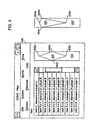
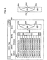
- a window 400 is depicted including nine items X to X+9 in subsets A to D. Each subset is a "connected" subset in which all of the elements within a subset are contiguous. Marker 402, a diamond shaped marker, is displayed in association with window 400 in rectangle 403.
- point 402a indicates the upper extent of subset B
- point 402b indicates the lower extent of subset B
- Point 402c and 402d indicate the center of subset B.
- marker 404 may be displayed in association with window 400.
- Marker 404 is displayed as a deformed diamond shape, a diamond that is symmetrical only along a single axis or line.
- Point 404a indicates the upper extent of subset B, item X+1, while point 404b indicates the lower extent of subset B, item X+6, in window 400.
- Item X+1 is the location currently selected by the user in Figure 4.
- Points 404c and 404d indicate the center of item X+1, which is the location of the item currently selected by the user.
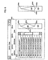
- item X+3 is the current item in subset B that has been selected by the user.
- Marker 402 is unchanged, while marker 404 has been altered such that points 404c and 404d indicate the center of item X+3, the item currently selected by the user.
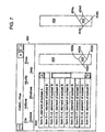
- item X+5 of subset B is the current item in window 400.
- markers 402 and 404 indicate the extent of subset C, which includes items X+7 and X+8.
- Point 402a indicates the top of subset C, item X+7, while point 402b indicates the bottom of subset C, item X+8.
- point 404a indicates the top of subset C while point 404b indicates the bottom of subset C.
- Points 402c and 402d graphically indicate the middle of subset C while points 404c and 404d indicate the item X+7 is the current item in subset C.
- subset D is the subset indicated by markers 402 and 404. As can be seen, a portion of subset D is not visible within window 400. Specifically, only item X+9 is visible within subset D. Items X+10 and X+11 are not displayed within window 400. Point 402a in marker 402 points to the top extent of subset D, item X+9. Point 402b is not visible because the bottom extent of subset D, X+11, is not visible. Similarly, points 402c and 402d are not visible within window 400. Turning to marker 404, point 404a points to the top portion of subset D. Point 404b is not visible and points 404c and 404d indicate that item X+9 is the current item in subset D.
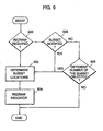
- FIG. 9 a high level flow chart of a process for indicating subsets displayed within a window is illustrated in accordance with a preferred embodiment of the present invention.
- the process begins by determining whether a redraw is required (step 500). If a redraw is required, the process then determines subset locations (step 502). the indicator is then redrawn after subset locations are determined (step 504). Referring again to step 500, if a redraw is not required, the process then determines whether a subset has been modified (step 506). If the subset is modified, the subset locations are determined (step 502), and the indicator is redrawn (step 504). If the subset has not been modified, the process then determines whether a different number of the subset has been selected (step 508).
- the subset locations are determined (step 502) and the indicator is redrawn (step 504). Otherwise, the process terminates.
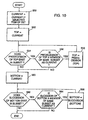
- the process begins by setting CURRENT equal to the currently selected item of the set (step 550). CURRENT is the current item for the subset. The process then sets TOP equal to CURRENT (step 552). TOP is the top item in the subset. The process then determines whether the predecessor of TOP exists in the subset (step 554). If the predecessor of TOP exists in the subset, the process then determines whether the predecessor of TOP is a member of the same subset as CURRENT (step 556). If the answer to step 556 is yes, TOP is set equal to PREDECESSOR (TOP), the predecessor of TOP (step 558). Thereafter, the process returns to step 554. If the answer is no in either step 554 or step 556, the process then sets BOTTOM equal to CURRENT (step 560). BOTTOM is the bottom item in the subset.
- TOP PREDECESSOR
- the process determines whether successor of BOTTOM exists in the subset (step 562). If the successor of BOTTOM does exist in the subset, the process then determines whether the successor of BOTTOM is a member of the same subset as CURRENT (step 564). If the answer is yes, the process sets BOTTOM equal to SUCCESSOR (BOTTOM), successor of BOTTOM (step 566). Thereafter, the process returns to step 562. If the answer in either step 562 or step 564 is no, the process then terminates.
- BOTTOM SUCCESSOR
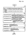
- FIG 11 a process for redrawing the indicator, as depicted in step 504 in Figure 9 is illustrated in accordance with a preferred embodiment of the present invention.
- the process begins by setting Top.y equal to the y coordinate of top-most extent of member TOP; Bottom.y equal to the y coordinate of bottom-most extent of member BOTTOM; Current.y equal to the y coordinate of the vertical center of member CURRENT (step 600).
- IndicatorWindow.left equal to the coordinate of left-most extent of the rectangle reserved for graphic indicator
- IndicatorWindow.right equal to the coordinate of right-most extent of the rectangle reserved for graphic indicator
- IndicatorWindow.top equal to the y coordinate of top extent of rectangle reserved for graphic indicator
- IndicatorWindow.bottom equal to the y coordinate of the bottom extent of rectangle reserved for graphic indicator (step 602).
- the process sets IndicatorTop.x equal to (IndicatorWindow.left+ IndicatorWindow.right)/2 and IndicatorTop.y equal to Top.y (step 604).
- the process sets IndicatorBottom.x equal to (IndicatorWindow.left + IndicatorWindow.right)/2 and IndicatorBottom y equal to Bottom.y (step 605).
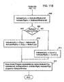
- a standard diamond draw involves drawing a diamond shaped polygon that is symmetrical about two axes.
- a nonstandard diamond draw involves drawing a deformed diamond shaped polygon. If a standard diamond draw is to be performed, the process sets IndicatorLeft.y equal to (Top.y+Bottom.y)/2 and IndicatorRight.y equal to (Top.y+Bottom.y)/2 (step 610). Then, the process draws a closed polygon represented by the points IndicatorTop, IndicatorLeft, IndicatorBottom, IndicatorRight, and IndicatorTop clipped to the indicator window (step 612).
- the process then sets IndicatorLeft.y equal to Current.y and IndicatorRight.y equal to Current.y (step 614).
Landscapes
- Engineering & Computer Science (AREA)
- General Engineering & Computer Science (AREA)
- Theoretical Computer Science (AREA)
- Human Computer Interaction (AREA)
- Physics & Mathematics (AREA)
- General Physics & Mathematics (AREA)
- User Interface Of Digital Computer (AREA)
- Digital Computer Display Output (AREA)
Claims (9)
- Verfahren in einem Datenverarbeitungssystem, das Daten enthält, die eine Vielzahl von Datenuntergruppen haben, wobei das Verfahren Folgendes umfasst:Anzeigen eines Anzeigefensters, wobei die Daten innerhalb des Anzeigefensters angezeigt werden;Auswählen einer Datenuntergruppe innerhalb der Vielzahl von Datenuntergruppen, welche die Daten umfassen; undwobei das Verfahren dadurch gekennzeichnet ist, dassin Verbindung mit dem Anzeigefenster als Reaktion auf die Auswahl eines Gliedes der Datenuntergruppe ein Markierer angezeigt wird, wobei der Markierer zwei Endpunkte hat, einen oberen Endpunkt und einen unteren Endpunkt, wobei ein Standort des oberen Endpunktes einen oberen Rand der Datenmenge anzeigt und ein Standort des unteren Endpunktes einen unteren Rand der Datenmenge anzeigt und wobei ein Fehlen eines der beiden Endpunkte einem Benutzer augenscheinlich ein Vorhandensein von zusätzlichen nicht angezeigten Daten innerhalb der Datenuntergruppe anzeigt.
- Verfahren nach Anspruch 1, wobei der Schritt des Anzeigens des Markierers, der zwei Endpunkte hat, einen oberen Endpunkt und einen unteren Endpunkt, wobei der obere Endpunkt einen oberen Rand der Datenuntergruppe anzeigt und der untere Endpunkt einen unteren Rand der Datenmenge anzeigt, das Anzeigen eines Polygons umfasst, das in Verbindung mit dem Anzeigefenster zwei Endpunkte hat, einen oberen Endpunkt und einen unteren Endpunkt, wobei der obere Endpunkt einen oberen Rand der Datenmenge anzeigt und der untere Endpunkt einen unteren Rand der Datenuntergruppe anzeigt.
- Verfahren nach Anspruch 1, wobei der Schritt des Anzeigens des Markierers, der zwei Endpunkte hat, einen oberen Endpunkt und einen unteren Endpunkt, wobei der obere Endpunkt einen oberen Rand der ausgewählten Datenmenge und der untere Endpunkt einen unteren Rand der ausgewählten Datenmenge anzeigt, das Anzeigen eines rautenförmigen Polygons umfasst, das einen oberen und unteren Punkt hat, wobei der obere Endpunkt als oberer Punkt und der untere Endpunkt als unterer Punkt bezeichnet werden.
- Verfahren nach Anspruch 3, wobei das rautenförmige Polygon einen rechten und linken Punkt hat und wobei der Schritt des Anzeigens weiterhin das Anzeigen des rechten und linken Punktes auf der Hälfte zwischen dem oberen Punkt und dem unteren Punkt umfasst.
- Verfahren nach Anspruch 3, wobei die Untermenge eine Vielzahl von Einträgen umfasst und weiterhin das Auswählen eines aus der Vielzahl der Einträge innerhalb der Datenuntergruppe umfasst.
- Verfahren nach Anspruch 5, wobei das rautenförmige Polygon einen rechten und linken Punkt hat, und wobei der Schritt des Anzeigens weiterhin das Anzeigen des rechten und linken Punktes entlang einer Linie umfasst, die den ausgewählten Eintrag schneidet.
- Verfahren nach Anspruch 4, 5 oder 6, wobei der Schritt des Anzeigens eines Markierers weiterhin das Anzeigen einer ersten Seite und einer zweiten Seite für den Markierer umfasst, wobei jede Seite eine Neigung hat, wobei die Neigung einem Benutzer augenscheinlich einen Abstand eines fehlenden Endpunktes von dem rechten Punkt und dem linken Punkt des Markierers anzeigt.
- Datenverarbeitungssystem, das Daten enthält, die eine Vielzahl von Datenuntergruppen haben, wobei das Datenverarbeitungssystem Folgendes umfasst:
Mittel, die geeignet sind, die Verfahren nach einem beliebigen der Ansprüche 1 bis 7 auszuführen. - Speichervorrichtung, die von einem Datenverarbeitungssystem lesbar ist und welche die ausführbaren Befehle codiert, die dann, wenn sie auf dem Datenverarbeitungssystem ausgeführt werden, die Verfahren ausführen, wie sie in den Ansprüchen 1 bis 7 definiert wurden.
Applications Claiming Priority (2)
| Application Number | Priority Date | Filing Date | Title |
|---|---|---|---|
| US298704 | 1994-08-31 | ||
| US08/298,704 US5592604A (en) | 1994-08-31 | 1994-08-31 | Method and system for indicating boundaries of connected data subsets |
Publications (3)
| Publication Number | Publication Date |
|---|---|
| EP0699993A2 EP0699993A2 (de) | 1996-03-06 |
| EP0699993A3 EP0699993A3 (de) | 1996-09-25 |
| EP0699993B1 true EP0699993B1 (de) | 2001-10-24 |
Family
ID=23151677
Family Applications (1)
| Application Number | Title | Priority Date | Filing Date |
|---|---|---|---|
| EP95480113A Expired - Lifetime EP0699993B1 (de) | 1994-08-31 | 1995-08-08 | Verfahren und Vorrichtung zur Anzeige der Ränder von verbundenen Datenuntergruppen |
Country Status (4)
| Country | Link |
|---|---|
| US (1) | US5592604A (de) |
| EP (1) | EP0699993B1 (de) |
| JP (1) | JP3122342B2 (de) |
| DE (1) | DE69523394D1 (de) |
Families Citing this family (12)
| Publication number | Priority date | Publication date | Assignee | Title |
|---|---|---|---|---|
| US6204846B1 (en) * | 1999-02-16 | 2001-03-20 | International Business Machines Corporation | Data set user interface control for use in accessing information in a computer |
| US8397177B2 (en) * | 1999-07-22 | 2013-03-12 | Tavusi Data Solutions Llc | Graphic-information flow method and system for visually analyzing patterns and relationships |
| US8843850B2 (en) * | 1999-07-22 | 2014-09-23 | Tavusi Data Solutions Llc | Graphic-information flow for visually analyzing patterns and relationships |
| US6307573B1 (en) * | 1999-07-22 | 2001-10-23 | Barbara L. Barros | Graphic-information flow method and system for visually analyzing patterns and relationships |
| US20050134578A1 (en) | 2001-07-13 | 2005-06-23 | Universal Electronics Inc. | System and methods for interacting with a control environment |
| EP1510911A3 (de) * | 2003-08-28 | 2006-03-22 | Sony Corporation | Gerät, Verfahren und Programm zum Verarbeiten von Informationen und Speichermedium mit Programm zum Verarbeiten von Informationen |
| US7836408B1 (en) * | 2004-04-14 | 2010-11-16 | Apple Inc. | Methods and apparatus for displaying relative emphasis in a file |
| US20070234238A1 (en) * | 2005-03-10 | 2007-10-04 | Kabushiki Kaisha Toshiba | Document searching apparatus |
| KR20080086265A (ko) * | 2007-03-22 | 2008-09-25 | 삼성전자주식회사 | 디스플레이 화면의 스크롤 시스템 및 스크롤 방법, 그시스템을 포함하는 모바일 단말과 그 방법을 수행하는프로그램이 기록된 기록 매체 |
| US8438503B2 (en) | 2009-09-02 | 2013-05-07 | Universal Electronics Inc. | System and method for enhanced command input |
| US9864501B2 (en) * | 2010-07-30 | 2018-01-09 | Apaar Tuli | Displaying information |
| CN106573799A (zh) * | 2014-07-29 | 2017-04-19 | 株式会社E-Plan | 电解离子水的生成方法和电解离子水生成装置 |
Family Cites Families (13)
| Publication number | Priority date | Publication date | Assignee | Title |
|---|---|---|---|---|
| US4868785A (en) * | 1987-01-27 | 1989-09-19 | Tektronix, Inc. | Block diagram editor system and method for controlling electronic instruments |
| US5233687A (en) * | 1987-03-25 | 1993-08-03 | Xerox Corporation | User interface with multiple workspaces for sharing display system objects |
| US5394521A (en) * | 1991-12-09 | 1995-02-28 | Xerox Corporation | User interface with multiple workspaces for sharing display system objects |
| US4896291A (en) * | 1988-05-20 | 1990-01-23 | International Business Machines Corporation | Valuator menu for use as a graphical user interface tool |
| US5016170A (en) * | 1988-09-22 | 1991-05-14 | Pollalis Spiro N | Task management |
| US5339392A (en) * | 1989-07-27 | 1994-08-16 | Risberg Jeffrey S | Apparatus and method for creation of a user definable video displayed document showing changes in real time data |
| US5185857A (en) * | 1989-12-13 | 1993-02-09 | Rozmanith A Martin | Method and apparatus for multi-optional processing, storing, transmitting and retrieving graphical and tabular data in a mobile transportation distributable and/or networkable communications and/or data processing system |
| US5179652A (en) * | 1989-12-13 | 1993-01-12 | Anthony I. Rozmanith | Method and apparatus for storing, transmitting and retrieving graphical and tabular data |
| US5337405A (en) * | 1990-10-02 | 1994-08-09 | Hewlett-Packard Company | Guided data presentation |
| US5204947A (en) * | 1990-10-31 | 1993-04-20 | International Business Machines Corporation | Application independent (open) hypermedia enablement services |
| US5295242A (en) * | 1990-11-02 | 1994-03-15 | Consilium, Inc. | Apparatus and method for viewing relationships in a factory management system |
| EP0509160A1 (de) * | 1991-04-16 | 1992-10-21 | International Business Machines Corporation | Datenverarbeitungssystem mit Bildfenstern |
| US5414809A (en) * | 1993-04-30 | 1995-05-09 | Texas Instruments Incorporated | Graphical display of data |
-
1994
- 1994-08-31 US US08/298,704 patent/US5592604A/en not_active Expired - Lifetime
-
1995
- 1995-08-08 DE DE69523394T patent/DE69523394D1/de not_active Expired - Lifetime
- 1995-08-08 EP EP95480113A patent/EP0699993B1/de not_active Expired - Lifetime
- 1995-08-25 JP JP07216962A patent/JP3122342B2/ja not_active Expired - Fee Related
Also Published As
| Publication number | Publication date |
|---|---|
| EP0699993A3 (de) | 1996-09-25 |
| JP3122342B2 (ja) | 2001-01-09 |
| JPH0883159A (ja) | 1996-03-26 |
| EP0699993A2 (de) | 1996-03-06 |
| DE69523394D1 (de) | 2001-11-29 |
| US5592604A (en) | 1997-01-07 |
Similar Documents
| Publication | Publication Date | Title |
|---|---|---|
| US5990888A (en) | Method and system for manipulating graphical objects | |
| US5629857A (en) | Method and system for indicating a status of a circuit design | |
| US5838316A (en) | Method and system for presenting a plurality of animated display objects to a user for selection on a graphical user interface in a data processing system | |
| US4945504A (en) | Instruction input system for electronic processor | |
| US5671378A (en) | Method and system for sizing of graphical user interface objects for localization | |
| US5412776A (en) | Method of generating a hierarchical window list in a graphical user interface | |
| US6215490B1 (en) | Task window navigation method and system | |
| US6259432B1 (en) | Information processing apparatus for improved intuitive scrolling utilizing an enhanced cursor | |
| US7536410B2 (en) | Dynamic multi-dimensional scrolling | |
| EP0699993B1 (de) | Verfahren und Vorrichtung zur Anzeige der Ränder von verbundenen Datenuntergruppen | |
| EP0703563A2 (de) | Verfahren und Einrichtung zur Anzeige überlappender graphischer Objekte auf einem Computermonitor | |
| US5920688A (en) | Method and operating system for manipulating the orientation of an output image of a data processing system | |
| US5680561A (en) | Effectively locating an object within a compound document using an elevator | |
| EP0595387A2 (de) | Verfahren und System zur multidimensionalen Verschiebung von angezeigten Datensätzen in einem Datenverarbeitungssystem | |
| EP0428261A2 (de) | Rechnerbenutzerschnittstelle | |
| US5842177A (en) | Management of calendar events in a data processing system | |
| EP0851349A2 (de) | Dynamischer Puffer und Verfahren zur Darstellung von ausgeschnitten Objekten | |
| US6337702B1 (en) | Method and system for graphically indicating a valid input within a graphical user interface | |
| EP0810514B1 (de) | Verfahren und System zur Erkennung von Zeigern | |
| US5602563A (en) | Float to surface display | |
| US5513311A (en) | Method and system for creating logical connections in a data processing system | |
| US5796383A (en) | Method and system for presenting contents of a container object within a graphical user interface in a data processing system | |
| AU623468B2 (en) | Depth buffer clipping for window management | |
| US5764215A (en) | Method and system for generating a global hit test data structure using scan line compression of windows in a graphical user interface | |
| EP0686924A2 (de) | Methode und System zum Herstellen von logischen Verbindungen in einem Datenverarbeitungssystem |
Legal Events
| Date | Code | Title | Description |
|---|---|---|---|
| PUAI | Public reference made under article 153(3) epc to a published international application that has entered the european phase |
Free format text: ORIGINAL CODE: 0009012 |
|
| AK | Designated contracting states |
Kind code of ref document: A2 Designated state(s): DE FR GB |
|
| PUAL | Search report despatched |
Free format text: ORIGINAL CODE: 0009013 |
|
| 17P | Request for examination filed |
Effective date: 19960626 |
|
| AK | Designated contracting states |
Kind code of ref document: A3 Designated state(s): DE FR GB |
|
| GRAG | Despatch of communication of intention to grant |
Free format text: ORIGINAL CODE: EPIDOS AGRA |
|
| 17Q | First examination report despatched |
Effective date: 20001227 |
|
| GRAG | Despatch of communication of intention to grant |
Free format text: ORIGINAL CODE: EPIDOS AGRA |
|
| GRAH | Despatch of communication of intention to grant a patent |
Free format text: ORIGINAL CODE: EPIDOS IGRA |
|
| GRAH | Despatch of communication of intention to grant a patent |
Free format text: ORIGINAL CODE: EPIDOS IGRA |
|
| GRAA | (expected) grant |
Free format text: ORIGINAL CODE: 0009210 |
|
| AK | Designated contracting states |
Kind code of ref document: B1 Designated state(s): DE FR GB |
|
| REF | Corresponds to: |
Ref document number: 69523394 Country of ref document: DE Date of ref document: 20011129 |
|
| REG | Reference to a national code |
Ref country code: GB Ref legal event code: IF02 |
|
| PG25 | Lapsed in a contracting state [announced via postgrant information from national office to epo] |
Ref country code: DE Free format text: LAPSE BECAUSE OF FAILURE TO SUBMIT A TRANSLATION OF THE DESCRIPTION OR TO PAY THE FEE WITHIN THE PRESCRIBED TIME-LIMIT Effective date: 20020125 |
|
| ET | Fr: translation filed | ||
| PLBE | No opposition filed within time limit |
Free format text: ORIGINAL CODE: 0009261 |
|
| STAA | Information on the status of an ep patent application or granted ep patent |
Free format text: STATUS: NO OPPOSITION FILED WITHIN TIME LIMIT |
|
| 26N | No opposition filed | ||
| PGFP | Annual fee paid to national office [announced via postgrant information from national office to epo] |
Ref country code: GB Payment date: 20030804 Year of fee payment: 9 |
|
| PGFP | Annual fee paid to national office [announced via postgrant information from national office to epo] |
Ref country code: FR Payment date: 20030825 Year of fee payment: 9 |
|
| PG25 | Lapsed in a contracting state [announced via postgrant information from national office to epo] |
Ref country code: GB Free format text: LAPSE BECAUSE OF NON-PAYMENT OF DUE FEES Effective date: 20040808 |
|
| GBPC | Gb: european patent ceased through non-payment of renewal fee |
Effective date: 20040808 |
|
| PG25 | Lapsed in a contracting state [announced via postgrant information from national office to epo] |
Ref country code: FR Free format text: LAPSE BECAUSE OF NON-PAYMENT OF DUE FEES Effective date: 20050429 |
|
| REG | Reference to a national code |
Ref country code: FR Ref legal event code: ST |