EP0700071B1 - Gasentladungsröhre - Google Patents
Gasentladungsröhre Download PDFInfo
- Publication number
- EP0700071B1 EP0700071B1 EP95306073A EP95306073A EP0700071B1 EP 0700071 B1 EP0700071 B1 EP 0700071B1 EP 95306073 A EP95306073 A EP 95306073A EP 95306073 A EP95306073 A EP 95306073A EP 0700071 B1 EP0700071 B1 EP 0700071B1
- Authority
- EP
- European Patent Office
- Prior art keywords
- anode
- shielding member
- discharge
- electrode
- hot cathode
- Prior art date
- Legal status (The legal status is an assumption and is not a legal conclusion. Google has not performed a legal analysis and makes no representation as to the accuracy of the status listed.)
- Expired - Lifetime
Links
- 239000000919 ceramic Substances 0.000 claims description 10
- 239000012212 insulator Substances 0.000 claims description 4
- 238000007789 sealing Methods 0.000 claims description 3
- 239000011521 glass Substances 0.000 description 10
- 230000017525 heat dissipation Effects 0.000 description 7
- YZCKVEUIGOORGS-OUBTZVSYSA-N Deuterium Chemical compound [2H] YZCKVEUIGOORGS-OUBTZVSYSA-N 0.000 description 6
- 229910052805 deuterium Inorganic materials 0.000 description 6
- 238000010891 electric arc Methods 0.000 description 6
- 238000003466 welding Methods 0.000 description 6
- 230000004308 accommodation Effects 0.000 description 5
- 229910052751 metal Inorganic materials 0.000 description 5
- 239000002184 metal Substances 0.000 description 5
- 230000008018 melting Effects 0.000 description 3
- 238000002844 melting Methods 0.000 description 3
- 229910001220 stainless steel Inorganic materials 0.000 description 3
- 239000010935 stainless steel Substances 0.000 description 3
- 239000000463 material Substances 0.000 description 2
- ZOKXTWBITQBERF-UHFFFAOYSA-N Molybdenum Chemical compound [Mo] ZOKXTWBITQBERF-UHFFFAOYSA-N 0.000 description 1
- 230000000694 effects Effects 0.000 description 1
- 238000004811 liquid chromatography Methods 0.000 description 1
- 230000004048 modification Effects 0.000 description 1
- 238000012986 modification Methods 0.000 description 1
- 229910052750 molybdenum Inorganic materials 0.000 description 1
- 239000011733 molybdenum Substances 0.000 description 1
- 238000005192 partition Methods 0.000 description 1
- 230000002035 prolonged effect Effects 0.000 description 1
Images





Classifications
-
- H—ELECTRICITY
- H01—ELECTRIC ELEMENTS
- H01J—ELECTRIC DISCHARGE TUBES OR DISCHARGE LAMPS
- H01J61/00—Gas-discharge or vapour-discharge lamps
- H01J61/02—Details
- H01J61/04—Electrodes; Screens; Shields
-
- G—PHYSICS
- G01—MEASURING; TESTING
- G01J—MEASUREMENT OF INTENSITY, VELOCITY, SPECTRAL CONTENT, POLARISATION, PHASE OR PULSE CHARACTERISTICS OF INFRARED, VISIBLE OR ULTRAVIOLET LIGHT; COLORIMETRY; RADIATION PYROMETRY
- G01J3/00—Spectrometry; Spectrophotometry; Monochromators; Measuring colours
- G01J3/02—Details
- G01J3/10—Arrangements of light sources specially adapted for spectrometry or colorimetry
-
- H—ELECTRICITY
- H01—ELECTRIC ELEMENTS
- H01J—ELECTRIC DISCHARGE TUBES OR DISCHARGE LAMPS
- H01J61/00—Gas-discharge or vapour-discharge lamps
- H01J61/02—Details
- H01J61/04—Electrodes; Screens; Shields
- H01J61/10—Shields, screens, or guides for influencing the discharge
Definitions
- the present invention relates to a gas discharge tube and, more particularly, but not exclusively, to a gas discharge tube used as an ultraviolet light source for a spectrophotometer, liquid chromatography, or the like.
- a conventional gas discharge tube is disclosed in Japanese Patent Laid-Open No. 4-255662. Accordingly to this prior art, a cathode and an anode, both of which are held by only lead lines, are disposed in a vessel, in which deuterium gas is sealed.
- EP-A-473378 describes a gas discharge tube in which an anode, a cathode and a first shield cover for surrounding these electrodes are disposed.
- a second shield cover is disposed within the first shield cover and at a position adjacent the anode to divide an internal space defined by the first shield cover into a first chamber in which the anode is positioned and a second chamber in which the cathode is positioned.
- the present invention aims to provide a gas discharge tube which improves the operational stability during long-time continuous light emission and has a long service life.
- the anode If the anode generates heat upon reception of the thermoelectrons during long-time light emission, the anode itself is heated to a high temperature exceeding several hundred °C, and a mechanical distortion is generated to change the distance between the anode and the focusing electrode plate. This change of distance results in that light emission of the gas discharge tube becomes unstable, and that the service life of the discharge tube is also undesirably shortened.
- the present invention provides a gas discharge tube comprising: an envelope for sealing a gas therein; a hot cathode disposed in said envelope, for emitting thermoelectrons; an anode disposed in said envelope, for receiving the thermoelectrons emitted from said hot cathode; a focusing electrode disposed in said envelope, said focusing electrode having a focusing opening for converging and passing through thermoelectrons which are emitted from said hot cathode and which is received by said anode; and a discharge shielding member having a front surface which faces to said hot cathode, characterised in that the discharge shielding member is of an insulator, and that said front surface of said discharge shielding member being defined by: a first surface being in direct contact with said focusing electrode, for defining a position of said focusing electrode; a second surface continued from said first surface, for defining a distance between said focusing electrode and said anode; and third surface continued from said second surface, said third surface being in direct contact with said anode, for
- a gas discharge tube comprises: an envelope 1 (glass vessel) for sealing a gas therein; lead pins 4a to 4e introduced into an inner space of the envelope 1 from external of the envelope 1; and a light-emitting section 2 in the envelope 1, positioned at distal ends of the lead pins and supported by the lead pins while spaced from an inner side wall 1A of the envelope 1.
- the light-emitting section 2 includes; a hot cathode 7 for emitting thermoelectrodes; an anode 8 for receiving the thermoelectrons emitted from the hot cathode 7; a focusing electrode 13 having a focusing opening 14a for converging and passing through thermoelectrons which are emitted from the hot cathode 7 and which are received by the anode 8; and a discharge shielding member 6 of an insulator (for example, ceramic, etc.) having a front surface which faces to the hot cathode 7.
- an insulator for example, ceramic, etc.
- the front surface of the discharge shielding member 6 is defined by: a first surface 601 being in direct contact with the focusing electrode 13, for defining a position of the focusing electrode 13; a second surface 602 continued form the first surface 601, for defining a distance between the focusing electrode 13 and the anode 8; and a third surface 603 continued from the second surface 602, the third surface 603 being in directly contact with the anode 8, for defining a position of the anode 8.
- the second and third surfaces 602 and 603 of the front surface of the discharge shielding member 6 constitutes a first depression 19 for accommodating the anode 8. Therefore, the third surface 603 is corresponded to a bottom surface of the first depression 19 of the discharge shielding member 6, and the second surface 602 functions so as to define a distance between the focusing electrode 13 and the anode 8 at the time that the focusing electrode 13 is mounted on the first surface 601 and the anode 8 is mounted on the third surface 603.
- the discharge shielding member 6 further has a rear surface 6A which is opposite to the front surface of the discharge shielding member 6 and through holes 22a and 22b passing from the bottom surface (third surface 603) of the first depression 19 to the rear surface 6A of the discharge shielding member 6.
- the anode 8 has a front surface 8A which faces to the focusing electrode 13 and a rear surface 8B which faces to the third surface 603 of the discharge shielding member 6, and a base portion 21c of a U-shaped connecting pin 21 is fixed on the rear surface 8B of the anode 8.
- the discharge shielding member 6 further has a second depression 20 at the third surface 603 of the front surface of the discharge shielding member 6, and the second depression 20 functions as a heat dissipation space of the anode 8.
- end portions 21a and 21b of the U-shaped connecting pin 21 are respectively passed through the through holes 22a and 22b and project from the rear surface 6A of the discharge shielding member 6 along a horizontal direction with respect to a surface 3A of the stem 3.
- the anode 3 is closely mounted on the discharge shielding member 6. Additionally, at least one of end portions 21a and 21b of the connecting pin 21 is fixed at a distal end of a lead pin 4e for setting the anode 8 a predetermined potential, the lead pin 4e introduced into an inner space of the envelope 1 from external of the envelope 1.
- the gas discharge tube further comprises: a front electrode 5 mounted on the front surface of the discharge shielding member 6, for accommodating the hot cathode 7 and shielding discharge of the hot cathode 7, thereby the hot cathode 7 is housed in a space defined by the front electrode 5 and the focusing electrode 13; and a cathode electrode 17 disposed in the space and separating a space for housing the hot cathode 7 from a space defined by the focusing opening 14a and the front electrode 5, for shielding discharge of the hot cathode 7.
- the front electrode 5 has a window 12 at a position opposite to the anode 8 through the focusing opening 14a of the focusing electrode 13, for outputting light occurred by gas discharge, and the cathode electrode 17 has a slit 17a for passing through the thermoelectrons emitted from the hot cathode 7 to the anode 8.
- a trigger voltage of, e.g., 350 to 500 V is applied between the hot cathode and the anode.
- Thermoelectrons emitted from the hot cathode are converged by the focusing electrode positioned between the hot cathode and the anode.
- arc discharge occurs in front of the focusing electrode.
- Light extracted from an arc ball by this arc discharge is externally projected from the closed vessel.
- the anode generates heat upon reception of the thermoelectrons.
- the anode itself is heated to a high temperature exceeding several hundred °C.
- the focusing electrode is mounted on and supported by the first surface of the front surface of the discharge shielding member, and the anode is mounted on and supported by the third surface (the bottom surface of the first depression) of the front surface of the discharge shielding member, the second surface of the front surface of the discharge shielding member functions so as to define the distance between the focusing electrode and the anode. For this reason, deformation of the anode or the focusing electrode hardly occurs, and a predetermined distance will be maintained between the anode and the focusing electrode.
- Fig. 1 is a perspective view showing the outer appearance of a side-on type gas discharge tube according to a first embodiment of the present invention.
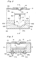
- Fig. 2 is a sectional view of the light-emitting section taken along a line A - A in Fig. 1.
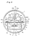
- Fig. 3 is a sectional view of the light-emitting section taken along the line B - B in Fig. 2.
- Fig. 4 is a longitudinal sectional view of the gas discharge tube shown in Fig. 1.
- Fig. 5 is a sectional view of the gas discharge tube taken along a line C - C in Fig. 4.
- Fig. 6 is an exploded perspective view of the light-emitting section of the gas discharge tube shown in Fig. 1.
- Fig. 7 is a front view of the gas discharge tube shown in Fig. 1.
- Fig. 8 is a rear view of the light-emitting section of the gas discharge tube shown in Fig. 1.
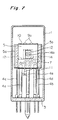
- Fig. 9 is a longitudinal sectional view showing a head-on type gas discharge tube according to a second embodiment of the present invention.
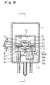
- Fig. 10 is a sectional view of the gas discharge tube taken along a line D - D in Fig. 9
- reference numeral 1 denotes a closed glass envelope (also to be called a glass valve).
- a light-emitting section assembly 2 is disposed in an inner space of the envelope 1 (glass vessel).
- the glass envelope 1 in which the deuterium is sealed at several Torr can be hermetically sealed.
- Lead pins 4a, 4b, and 4e, all of which are covered by a ceramic pipe, and bare lead pins 4c and 4d extend from the lower portion of the light-emitting section 2 to the surface 3A of the stem 3. These lead pins 4a to 4e extend through the stem 3 to be externally exposed.
- the light-emitting section 2 has a front electrode 5 as a front cover arranged at the front side of the light-emitting section 2 and made of a metal (Ni or Stainless Steel), and a ceramic discharge shielding member 6 arranged at the rear side of the light-emitting section 2.
- the entire front surface of the discharge shielding member 6 is covered by front cover assembly comprising the front electrode 5, an upper cover piece 10, and a lower cover piece 11, and a hot cathode 7 is housed in a space defined by the front cover assembly and the discharge shielding member 6.
- the front electrode 5 has a window 12 for outputting light occurred by gas discharge.
- the embodiments of this invention relate to for example U.S.Patent Application No. 08/305,972, Japanese Patent Laid-Open No. 4-255662, and the like. Particularly, a basic structure of the gas discharge tube and materials of members such as anode, etc. are described in these references.
- the discharge shielding member 6 is made of ceramic as insulator, and the anode plate 8 is made of molybdenum as high melting point metal.
- the high melting metal means material group having a higher melting point than sillicon (1414°C).
- the front surface of the ceramic discharge shielding member 6 of the light-emitting section 2 faces to hot cathode 7 for emitting thermoelectrons (shown in Fig. 4).
- the front surface of the discharge shielding member 6, as shown in Figs. 2 and 3, is defined by at least three surfaces.
- a first surface 601 of the front surface of the discharge shielding member 6 is in direct contact with the focusing electrode 13 having a focusing opening 14a for converging and passing through thermoelectrons which is emitted from the hot cathode 7 and which is received by the anode 8, and thereby the first surface 601 functions so as to define a position of the focusing electrode 13.
- a third surface 603 of the front surface of the discharge shielding member 6 is in directly contact with the anode 8 for receiving the thermoelectrons emitted from the hot cathode 7, and thereby the third surface 603 functions so as to define a position of the anode 8.
- a second surface 602 of the front surface of the discharge shielding member 6 connects the first surface 601 to the third surface 603, thereby the second surface 602 functions so as to define a distance between the focusing electrode 13 and the anode 8.
- the second and third surfaces 602 and 603 of the front surface of the discharge shielding member 6 constitutes a first depression 19 for accommodating the anode 8.
- the discharge shielding member 6 further has a second depression 20 for a heat dissipation of the anode 8, and has a rear surface 6A which is located at a rear surface side of the anode 8.
- the second depression 20 and the rear surface 6A of the discharge shielding member 6 are connected by through holes 22a and 22b.
- the anode 8 has a front surface 8A which faces to the focusing electrode 13 and a rear surface 8B which faces to the third surface 603 of the discharge shielding member 6, and a base portion 21c of a U-shaped connecting pin 21 is fixed on the rear surface 8B of the anode 8 and accommodated in the second depression 20.
- end portions 21a and 21b of the U-shaped connecting pin 21 are respectively passed through the through holes 22a and 22b and project from the rear surface 6A of the discharge shielding member 6 to external of the discharge shielding member 6, and these portions 21a and 21b are fixed by fixing means 23a and 23b at the rear surface side of the discharge shielding member 6.
- at least one of end portions 21a and 21b is fixed at a distal end of the lead pin 4e for setting the anode 8 a predetermined potential.
- a spiral hot cathode 7 having electrode rods 7a and 7b at the two ends thereof is in a space defined by the front cover assembly and the focusing electrode 13.
- the front cover assembly is constituted by the front electrode 5, an upper cover piece 10 arranged at an upper portion of the front electrode 5 (a top surface side of the glass envelope 1), and a lower cover piece 11 arranged at a bottom portion of the front electrode 5 (stem side).
- a rectangular flat plate-like anode 8 is accommodated in the discharge shielding member 6.
- the front electrode 5 is bent to have a substantially U-shaped section, and flange portions 5a and 5b are integrally formed at its two ends.
- Pawl pieces 9a and 9b free to be bent and engaged with one end of the upper cover piece 10 or the lower cover piece 11, both of which are made of a metal (Ni or Stainless Steel), are formed at the head and bottom portions of the front electrode 5.
- An opening window 12 for projecting light is formed in the front electrode 5 at its center.
- Through holes 11a and 11b through which the two cathode lead pins 4a and 4b extend are formed in the lower cover piece 11.
- a focusing electrode plate 13 for converging thermoelectrons is arranged between the front electrode 5 and the front surface of the discharge shielding member 6.
- the focusing electrode 13 serves as a cover on the rear surface side of the front electrode 5 and also constitutes a partition wall between the front electrode 5 and the discharge shielding member 6.
- a discharge focusing plate 14 is fixed at the center of a front surface 13A of the focusing electrode 13 to oppose the opening window 12 while a rear surface 13B of the focusing electrode 13 is in closely contact with the first surface 601 of the front surface of the discharge shielding member 6.
- a focusing opening 14a in parallel aligned with the opening window 12 at a predetermined interval is formed in the discharge focusing plate 14.
- the focusing opening 14a is tapered toward the anode 8 (see Figs.
- Pawl pieces 15a and 15b free to be bent and engaged with one end of the upper cover piece 10 or the lower cover piece 11 are formed at the head and bottom portions of the focusing electrode 13. Therefore, when the upper and lower cover pieces 10 and 11 are arranged to be brought into contact with the head and bottom surfaces of the front electrode 5 and the focusing electrode 13 while the upper and lower cover pieces 10 and 11 are respectively arranged in a horizontal direction with respect to the surface 3A of the glass stem 3, and the pawl pieces 9a and 9b and 15a and 15b are respectively bent inward so as to sandwich the upper and lower cover pieces 10 and 11, the upper and lower portions of the front electrode 5 can be closed.
- Flange portions 13a and 13b facing the flange portions 5a and 5b of the front electrode 5 are integrally formed at the two ends of the focusing electrode 13.
- Curved pin accommodation portions 16a and 16b are formed at the flange portions 13a and 13b in the longitudinal direction to accommodate the lead pins 4c and 4d for supporting the focusing electrode 13. Therefore, when the lead pins 4c and 4d are welded to the pin accommodation portions 16a and 16b, and thereafter, the flange portions 5a and 5b are welded to the flange portions 13a and 13b, the focusing electrode plate 13 can be properly fixed to the front electrode 5. As a result, each of the front electrode 5 and the focusing electrode 13 has a same voltage potential.
- a metal Ni or Stainless Steel
- each of the front electrode 5, the focusing electrode 13, and the cathode electrode 17 has a same potential.
- An elongated slit 17a for focusing thermoelectrons emitted from the hot cathode 7 is formed in the cathode electrode 17 at its center. Therefore, the cathode electrode 17, the lower cover piece 11, the front electrode 5, and the focusing electrode 13 constitute a space 18 for accommodating the hot cathode 7.
- the thermoelectrons emitted from the hot cathode 7 pass through the slit 17a and are converged toward the focusing opening 14a.
- the box-like discharge shielding member 6 is integrally formed of a ceramic having electrical insulating properties and a high thermal conductivity.
- the discharge shielding member 6 acts as a heat sink for the anode plate 8 heated to a high temperature and promotes dissipation of the heat accumulated in the light-emitting section 2.
- the discharge shielding member 6 has a first recessed portion 19, as an anode accommodation space for accommodating the anode plate 8, formed from the first surface 601 the front surface toward a rear surface 6A of the discharge shielding member 6.
- the periphery of the plate-like anode 8 is supported in contact with a bottom surface (the third surface 603 of the front surface of the discharge shielding member 6) of the first depression 19.
- the second depression 20 can also accommodate the base portion 21c of the U-shaped connecting pin 21 which is fixed to the rear surface 8B of the anode 8.
- a first end portion 21a and a second end portion 21b of the connecting pin 21 are respectively inserted into through holes 22a and 22b formed from a bottom surface 20a of the second depression 20 toward the rear surface 6A, as shown in Figs. 2 to 8, and can also project from the rear surface 6A of the discharge shielding member 6. Therefore, with a simple operation such that eyelets 23a and 23b as a fixing means are firmly fitted in the first and second end portions 21a and 21b projecting from the rear surface 6A, the connecting pin 21 will be fixed to the rear surface 6A of the discharge shielding member 6, and at the same time, the anode plate 8 will be supported in contact with the bottom surface 603 of the first depression 19.
- the focusing electrode 13 is firmly fixed to the first surface 601 of the front surface of the discharge shielding member 6 through four rivets 24. For this reason, when the flange portions 13a and 13b of the focusing electrode 13 are welded to the flange portions 5a and 5b in correspondence with each other, the front electrode 5 will be firmly fixed to the discharge shielding member 6.
- the first and second end portions 21a and 21b of the connecting pin 21 may be fixed to the rear surface 6A of the discharge shielding member 6 by welding or the like as a fixing means in place of the above eyelets 23a and 23b.
- the distal ends of the lead pins 4a and 4b are fixed to the electrode rods 7a and 7b of the hot cathode 7 by welding or the like.
- the distal end of the lead pin 4e is fixed to the second end portion 21b of the connecting pin 21 arranged on the rear surface 8B of the anode plate 8 by welding or the like.
- the distal ends of the lead pins 4c and 4d are fixed to the pin accommodation portions 16a and 16b of the focusing electrode 13 by welding or the like.
- the hot cathode 7 is energized and sufficiently heated. Thereafter, a predetermined trigger voltage (e.g., 350 to 500 V) is applied between the hot cathode 7 and the anode 8 through the lead pins 4a to 4e.
- Thermoelectrons emitted from the hot cathode 7 pass through the elongated slit 17a of the cathode electrode 17 and are converged by the focusing opening 14a of the focusing electrode plate 14, which is in directly contact with the front surface 13A of the focusing electrode plate 13, to reach the anode 8.
- arc discharge occurs in front of the focusing opening 14a.
- Ultraviolet light extracted from an arc ball by the arc discharge passes through the opening window 12 of the front electrode 5 and is externally emitted through the glass vessel 1.
- the anode plate 8 and the focusing electrode plate 13 are heated to a high temperature exceeding several hundred °C. This heat is dissipated through the ceramic discharge shielding member 6 as needed. Since the anode 8 and the focusing electrode 13 are firmly held by the discharge shielding member 6, deformation hardly occurs even in a high temperature state during long-time continuous light emission. Therefore, a high positional precision between the anode 8 and the focusing electrode 13 can be satisfactorily maintained.
- the present invention is not limited to the above embodiment and can also be applied to, e.g., a head-on type deuterium discharge tube as shown in Figs 9 and 10.
- a head-on type deuterium discharge tube as shown in Figs 9 and 10.
- the same reference numerals as in the above embodiment denote the same parts.
- the front electrode 5 is formed of a ceramic and fixed to the front surface of the discharge shielding member 6.
- the opening window 12 is formed in the front electrode 5 at its center portion so as to be used for the head-on type.
- a rear surface 13B of the focusing electrode 13 is fixed to the first surface 601 of the front surface of the discharge shielding member 6 and fixed to the distal ends of the lead pins 4c and 4d extending through the discharge shielding member 6 through eyelets 30.
- the hot cathode 7 is housed in the front electrode 5 to project from the focusing electrode 13.
- a discharge straightening plate 31 stands on the front surface 13A of the focusing electrode 13. This discharge straightening plate 31 is located between the hot cathode 7 and the discharge focusing plate 14 which is arranged at the center of the focusing electrode plate 13.
- the box-like discharge shielding member 6 is integrally formed of a ceramic having electrical insulating properties and a high thermal conductivity.
- the discharge shielding portion 6 has the first depression 19 formed from the first surface 601 of the front surface toward the rear surface 6A of the discharge shielding member 6.
- the periphery of the plate-like anode 8 is supported in contact with the bottom surface 603 of the second depression 19 for accommodating the anode plate 8.
- the second depression 20 is formed in the bottom surface 603 of the first depression 19 at its center to increase the heat dissipation efficiency of the anode 8.
- the second depression 20 will accommodate the base portion 21c of the U-shaped connecting pin 21 which is fixed to the rear surface 8B of the anode plate 8.
- the first and second end portions 21a and 21b of the connecting pin 21 project from the rear surface 6A of the discharge shielding member 6.
- the anode 8 will be firmly held by the bottom surface 603 of the first depression 19.
- the distal ends of the lead pins 4a and 4b are fixed to the electrode rods 7a and 7b of the hot cathode 7 by welding or the like.
- the distal end of the lead pin 4e is fixed to the second end portion 21b of the connecting pin 21 arranged on the rear surface 8B of the anode plate 8 by welding or the like.
- the rear surface of the focusing electrode 13 and the front surface 8A of the anode plate 8 are facing to each other.
- the hot cathode 7 is energized and sufficiently heated. Thereafter, a predetermined trigger voltage (e.g., 350 to 500 V) is applied between the hot cathode 7 and the anode 8 through the lead pins 4a to 4e.
- a predetermined trigger voltage e.g., 350 to 500 V
- Thermoelectrons emitted from the hot cathode 7 are straightened by the discharge straightening plate 31 and converged by the focusing opening 14a of the focusing electrode plate 14, which is directly on the front surface 13A of the focusing electrode 13, to reach the anode plate 8.
- arc discharge occurs in front of the focusing opening 14a.
- Ultraviolet light extracted from an arc ball by the arc discharge passes through the opening window 12 of the front electrode 5 and is externally emitted through the glass envelope 1.
- the gas discharge tube having the above arrangement will provide the following effect.
- the anode is supported by the bottom surface of the anode accommodation space (first depression) formed from the front surface to the rear surface of the discharge shielding member, and the focusing electrode plate is fixed to the front surface of the discharge member while keeping a constant distance from the anode plate.
- the anode and the focusing electrode are firmly held by the discharge shielding member, deformation hardly occurs even in a high temperature state during long-time continuous light emission. Therefore, a high positional precision between the anode and the focusing electrode plate will be satisfactorily maintained.
- the operational stability of the gas discharge tube will be improved, and the service life will be prolonged.
Landscapes
- Physics & Mathematics (AREA)
- Spectroscopy & Molecular Physics (AREA)
- General Physics & Mathematics (AREA)
- Discharge Lamp (AREA)
- Vessels And Coating Films For Discharge Lamps (AREA)
Claims (10)
- Gasentladungsröhre mit:dadurch gekennzeichnet, daßeinem Mantel (1), um ein Gas einzuschließen;einer Heißkathode (7), die in dem Mantel (1) angeordnet ist, um Thermoelektronen zu emittieren;einer Anode (8), die in dem Mantel (1) angeordnet ist, um von der Heißkathode (7) emittierte Thermoelektronen aufzunehmen;einer Fokussierelektrode (13), die in dem Mantel (1) angeordnet ist, wobei die Fokussierelektrode (13) eine Fokussieröffnung (14a) für ein Konvergieren und Durchleiten der Thermoelektronen haben, die von der Heißkathode (7) emittiert werden und die von der Anode (8) empfangen werden; undein Entladungsabschirmelement (6), das eine vordere Fläche hat, die der Heißkathode (7) zugewandt ist,
das Entladungsabschirmelement einen Isolator aufweist und die vordere Fläche des Entladungsabschirmelementes (6) definiert ist durch:eine erste Fläche (601), die in direktem Kontakt mit der Fokussierelektrode (13) steht, um eine Position der Fokussierelektrode (13) zu definieren;einer zweiten Fläche (602), die sich von der ersten Fläche (601) fortsetzt, um einen Abstand zwischen der Fokussierelektrode (13) und der Anode (8) zu definieren; undeiner dritten Fläche (603), die sich von der zweiten Fläche (602) fortsetzt, wobei die dritte Fläche (603) in direktem Kontakt mit der Anode (8) steht, um eine Position der Anode (8) zu definieren. - Gasentladungsröhre gemäß Patentanspruch 1, wobei die zweite und dritte Fläche (602, 603) der vorderen Fläche des Entladungsabschirmelementes (6) eine erste Vertiefung (19) für ein Unterbringen der Anode (8) bilden.
- Gasentladungsröhre gemäß Patentanspruch 1, wobei das Entladungsschutzelement (6) des weiteren eine hintere Fläche (6A), die der vorderen Fläche des Entladungsabschirmelementes (6) entgegengesetzt ist, und Durchgangslöcher (22a, 22b), die von der dritten Fläche (603) der vorderen Fläche zu der hinteren Fläche des Entladungsabschirmelementes (6) hindurchtreten, hat.
- Gasentladungsröhre gemäß Patentanspruch 3, der weiterhin einen Verbindungsstift (21) aufweist, der an einer hinteren Fläche (8b) der Anode (8) befestigt ist, wobei die hintere Fläche (8b) der Anode (8) in direktem Kontakt mit der dritten Fläche (603) der vorderen Fläche des Entladungsabschirmelementes (6)steht, wobei
beide Enden (21a, 21b) des Verbindungsstiftes (21) von der hinteren Fläche (6A) des Entladungsabschirmelementes (6) durch die Durchgangslöcher (22a, 22b) vorstehen. - Gasentladungsröhre gemäß Patentanspruch 4, wobei zumindest eines der Enden (21a, 21b) des Verbindungsstiftes (21) an einem entfernten Ende von einem Leitungsstift (4e) für ein Setzen der Anode (8) auf ein vorbestimmtes Potential befestigt ist, wobei der Leitungsstift (4e) in einen Innenraum des Mantels (1) von außerhalb des Mantels (1) eingeführt ist.
- Gasentladungsröhre gemäß Patentanspruch 1, die des weiteren eine Vorderelektrode (5) an der vorderen Fläche des Entladungsabschirmelementes (6) zum Unterbringen der heißen Kathode (7) und zum Abschirmen der Entladung der Heißkathode (7) aufweist, wobei die Heißkathode (7) in einem Raum untergebracht ist, der durch die Vorderelektrode (5) und die Fokussierelektrode (13) definiert ist.
- Gasentladungsröhre gemäß Patentanspruch 6, wobei die Vorderelektrode (5) ein Fenster (12) an einer Position, die der Anode (8) in Bezug auf die Fokussieröffnung (14a) der Fokussierelektrode (13) gegenübersteht, hat, um Licht abzugeben, das bei der Gasentladung entsteht.
- Gasentladungsröhre gemäß Patentanspruch 6, die des weiteren eine Kathodenelektrode (17) aufweist, die in dem Raum angeordnet ist, um die Entladung der Heißkathode (7) abzuschirmen, wobei die Kathodenelektrode (17) einen Schlitz (17a) für ein Hindurchtreten der Thermoelektronen, die von der Heißkathode (7) emittiert werden, hat.
- Gasentladungsröhre gemäß Patentanspruch 1, die des weiteren folgendes aufweist:einen Verbindungsstift (21), der an einer hinteren Fläche (8B) der Anode (8) befestigt ist, wobei die hintere Fläche (8B) der Anode (8) in direktem Kontakt mit der dritten Fläche (603) der vorderen Fläche des Entladungsabschirmelementes (6) steht; undeine zweite Vertiefung (20) zum teilweisen Unterbringen des Verbindungsstiftes (21) an der dritten Fläche (603) der vorderen Fläche des Entladungsabschirmelementes (6).
- Gasentladungsröhre gemäß Patentanspruch 1, wobei das Entladungsabschirmelement (6) aus Keramik hergestellt ist.
Applications Claiming Priority (3)
| Application Number | Priority Date | Filing Date | Title |
|---|---|---|---|
| JP6207715A JP2784148B2 (ja) | 1994-08-31 | 1994-08-31 | ガス放電管 |
| JP207715/94 | 1994-08-31 | ||
| JP20771594 | 1994-08-31 |
Publications (3)
| Publication Number | Publication Date |
|---|---|
| EP0700071A2 EP0700071A2 (de) | 1996-03-06 |
| EP0700071A3 EP0700071A3 (de) | 1997-05-21 |
| EP0700071B1 true EP0700071B1 (de) | 2000-07-19 |
Family
ID=16544363
Family Applications (1)
| Application Number | Title | Priority Date | Filing Date |
|---|---|---|---|
| EP95306073A Expired - Lifetime EP0700071B1 (de) | 1994-08-31 | 1995-08-31 | Gasentladungsröhre |
Country Status (4)
| Country | Link |
|---|---|
| US (1) | US5633563A (de) |
| EP (1) | EP0700071B1 (de) |
| JP (1) | JP2784148B2 (de) |
| DE (1) | DE69518045T2 (de) |
Cited By (1)
| Publication number | Priority date | Publication date | Assignee | Title |
|---|---|---|---|---|
| US7288893B2 (en) | 2003-02-12 | 2007-10-30 | Hamamatsu Photonics K.K. | Gas discharge tube |
Families Citing this family (23)
| Publication number | Priority date | Publication date | Assignee | Title |
|---|---|---|---|---|
| WO1999034408A1 (fr) * | 1997-12-24 | 1999-07-08 | Hamamatsu Photonics K.K. | Tube a decharge gazeuse |
| DE69825482T2 (de) | 1997-12-24 | 2005-08-18 | Hamamatsu Photonics K.K., Hamamatsu | Deuterium-gasenladungsröhre |
| JP4275853B2 (ja) * | 1997-12-24 | 2009-06-10 | 浜松ホトニクス株式会社 | ガス放電管 |
| JP4240437B2 (ja) * | 1997-12-24 | 2009-03-18 | 浜松ホトニクス株式会社 | ガス放電管 |
| WO1999034404A1 (fr) | 1997-12-24 | 1999-07-08 | Hamamatsu Photonics K.K. | Tube a decharge gazeuse |
| US5972469A (en) * | 1998-01-30 | 1999-10-26 | Imaging & Sensing Technology Corporation | Baffle for eliminating interference ring(s) from the output light pattern of a deuterium lamp |
| DE69812440T2 (de) | 1998-09-07 | 2004-01-08 | Hamamatsu Photonics K.K., Hamamatsu | Gasenladenungsröhre |
| JP2000173547A (ja) * | 1998-12-09 | 2000-06-23 | Hamamatsu Photonics Kk | ガス放電管 |
| JP4185214B2 (ja) | 1999-04-28 | 2008-11-26 | 浜松ホトニクス株式会社 | ポータブル型光源装置 |
| JP4183840B2 (ja) | 1999-04-28 | 2008-11-19 | 浜松ホトニクス株式会社 | ポータブル型光源装置 |
| US6690111B1 (en) * | 1999-06-15 | 2004-02-10 | Imaging & Sensing Technology Corporation | Lamp with anode support structure and anode surface configuration having improved heat dissipation properties |
| JP4326631B2 (ja) | 1999-07-16 | 2009-09-09 | 浜松ホトニクス株式会社 | 重水素ランプボックス及びポータブル型光源装置 |
| JP4964374B2 (ja) * | 2001-08-24 | 2012-06-27 | 浜松ホトニクス株式会社 | ガス放電管 |
| JP4907760B2 (ja) | 2000-11-15 | 2012-04-04 | 浜松ホトニクス株式会社 | ガス放電管 |
| JP4964360B2 (ja) | 2000-11-15 | 2012-06-27 | 浜松ホトニクス株式会社 | ガス放電管 |
| AU1429402A (en) | 2000-11-15 | 2002-05-27 | Hamamatsu Photonics Kk | Gas discharge tube |
| JP4964359B2 (ja) * | 2000-11-15 | 2012-06-27 | 浜松ホトニクス株式会社 | ガス放電管 |
| WO2002063649A2 (en) * | 2001-02-08 | 2002-08-15 | Imaging & Sensing Technology Corporation | Arc lamp having an electrical insulator portion with a gap connected to a transverse cavity therein |
| KR100912334B1 (ko) * | 2001-09-28 | 2009-08-14 | 하마마츠 포토닉스 가부시키가이샤 | 가스 방전관 |
| JP4006005B2 (ja) * | 2002-04-30 | 2007-11-14 | 浜松ホトニクス株式会社 | ガス放電管 |
| JP3984179B2 (ja) * | 2003-02-20 | 2007-10-03 | 浜松ホトニクス株式会社 | ガス放電管 |
| USD730217S1 (en) * | 2014-02-04 | 2015-05-26 | Hamamatsu Photonics K.K. | Spectrometer |
| DE102020128643B3 (de) | 2020-10-30 | 2022-02-03 | Heraeus Noblelight Gmbh | Deuteriumlampe |
Family Cites Families (13)
| Publication number | Priority date | Publication date | Assignee | Title |
|---|---|---|---|---|
| JPS59215654A (ja) * | 1983-05-24 | 1984-12-05 | Hamamatsu Photonics Kk | 改良された複合光源ランプ |
| JPS6020442A (ja) * | 1983-07-13 | 1985-02-01 | Fumio Watanabe | 質量分析計用熱陰極電子衝撃型イオン源 |
| JPS6029400A (ja) * | 1983-07-28 | 1985-02-14 | 日本電気株式会社 | デユアルスピン衛星用ロ−タリジヨイント装置 |
| JPS61179052A (ja) * | 1985-02-04 | 1986-08-11 | Hitachi Ltd | 水素発光管 |
| US4910431A (en) * | 1987-04-24 | 1990-03-20 | W. C. Heraeus Gmbh | Hydrogen discharge ultraviolet light source or lamp, and method of its manufacture |
| JPH02220347A (ja) * | 1989-02-21 | 1990-09-03 | Hamamatsu Photonics Kk | 放電管 |
| EP0473378B1 (de) * | 1990-08-27 | 1995-07-12 | Hamamatsu Photonics K.K. | Gasentladungsröhre |
| JPH04147557A (ja) * | 1990-10-11 | 1992-05-21 | Hitachi Ltd | 重水素放電管 |
| JPH04255662A (ja) * | 1991-02-08 | 1992-09-10 | Hitachi Ltd | 重水素放電管 |
| JPH04319248A (ja) * | 1991-04-18 | 1992-11-10 | Hitachi Ltd | 重水素放電管 |
| JP2740738B2 (ja) | 1994-05-31 | 1998-04-15 | 浜松ホトニクス株式会社 | ガス放電管 |
| JP2769436B2 (ja) | 1994-08-31 | 1998-06-25 | 浜松ホトニクス株式会社 | ガス放電管及びその点灯装置 |
| JP2740741B2 (ja) | 1994-08-31 | 1998-04-15 | 浜松ホトニクス株式会社 | ガス放電管 |
-
1994
- 1994-08-31 JP JP6207715A patent/JP2784148B2/ja not_active Expired - Fee Related
-
1995
- 1995-07-13 US US08/502,009 patent/US5633563A/en not_active Expired - Lifetime
- 1995-08-31 EP EP95306073A patent/EP0700071B1/de not_active Expired - Lifetime
- 1995-08-31 DE DE69518045T patent/DE69518045T2/de not_active Expired - Lifetime
Cited By (1)
| Publication number | Priority date | Publication date | Assignee | Title |
|---|---|---|---|---|
| US7288893B2 (en) | 2003-02-12 | 2007-10-30 | Hamamatsu Photonics K.K. | Gas discharge tube |
Also Published As
| Publication number | Publication date |
|---|---|
| US5633563A (en) | 1997-05-27 |
| JP2784148B2 (ja) | 1998-08-06 |
| DE69518045D1 (de) | 2000-08-24 |
| EP0700071A2 (de) | 1996-03-06 |
| DE69518045T2 (de) | 2001-03-22 |
| JPH0877979A (ja) | 1996-03-22 |
| EP0700071A3 (de) | 1997-05-21 |
Similar Documents
| Publication | Publication Date | Title |
|---|---|---|
| EP0700071B1 (de) | Gasentladungsröhre | |
| EP0727810B1 (de) | Gasentladungsröhre | |
| US5552669A (en) | Deuterium gas discharge tube | |
| EP0727811B1 (de) | Gasentladungsröhre | |
| US5587625A (en) | Gas discharge tube | |
| EP0700072B1 (de) | Gasentladungsröhre, Beleuchtungsvorrichtung mit einer solchen Gasentladungsröhre und Methode zum Betreiben einer solchen Beleuchtungsvorrichtung | |
| US6586866B1 (en) | Gas discharge tube having precise electrode arrangement | |
| EP0727812B1 (de) | Gasentladungsröhre | |
| JP3361402B2 (ja) | ガス放電管 | |
| EP1143486A1 (de) | Gasenladungsrohre | |
| US6531821B1 (en) | Gas discharge tube | |
| US20020011771A1 (en) | Gas discharge tube | |
| EP1780767B1 (de) | Gasentladungsröhre | |
| US7781975B2 (en) | Gas discharge tube having cathode cover made of ceramics | |
| EP1538660A1 (de) | Gasentladungsr hre |
Legal Events
| Date | Code | Title | Description |
|---|---|---|---|
| PUAI | Public reference made under article 153(3) epc to a published international application that has entered the european phase |
Free format text: ORIGINAL CODE: 0009012 |
|
| AK | Designated contracting states |
Kind code of ref document: A2 Designated state(s): DE FR GB IT SE |
|
| PUAL | Search report despatched |
Free format text: ORIGINAL CODE: 0009013 |
|
| AK | Designated contracting states |
Kind code of ref document: A3 Designated state(s): DE FR GB IT SE |
|
| 17P | Request for examination filed |
Effective date: 19971111 |
|
| 17Q | First examination report despatched |
Effective date: 19990201 |
|
| GRAG | Despatch of communication of intention to grant |
Free format text: ORIGINAL CODE: EPIDOS AGRA |
|
| GRAG | Despatch of communication of intention to grant |
Free format text: ORIGINAL CODE: EPIDOS AGRA |
|
| GRAH | Despatch of communication of intention to grant a patent |
Free format text: ORIGINAL CODE: EPIDOS IGRA |
|
| GRAH | Despatch of communication of intention to grant a patent |
Free format text: ORIGINAL CODE: EPIDOS IGRA |
|
| GRAA | (expected) grant |
Free format text: ORIGINAL CODE: 0009210 |
|
| AK | Designated contracting states |
Kind code of ref document: B1 Designated state(s): DE FR GB IT SE |
|
| ET | Fr: translation filed | ||
| REF | Corresponds to: |
Ref document number: 69518045 Country of ref document: DE Date of ref document: 20000824 |
|
| ITF | It: translation for a ep patent filed | ||
| PLBE | No opposition filed within time limit |
Free format text: ORIGINAL CODE: 0009261 |
|
| STAA | Information on the status of an ep patent application or granted ep patent |
Free format text: STATUS: NO OPPOSITION FILED WITHIN TIME LIMIT |
|
| 26N | No opposition filed | ||
| REG | Reference to a national code |
Ref country code: GB Ref legal event code: IF02 |
|
| PGFP | Annual fee paid to national office [announced via postgrant information from national office to epo] |
Ref country code: SE Payment date: 20070807 Year of fee payment: 13 Ref country code: IT Payment date: 20070828 Year of fee payment: 13 |
|
| PG25 | Lapsed in a contracting state [announced via postgrant information from national office to epo] |
Ref country code: IT Free format text: LAPSE BECAUSE OF NON-PAYMENT OF DUE FEES Effective date: 20080831 |
|
| PG25 | Lapsed in a contracting state [announced via postgrant information from national office to epo] |
Ref country code: SE Free format text: LAPSE BECAUSE OF NON-PAYMENT OF DUE FEES Effective date: 20080901 |
|
| PGFP | Annual fee paid to national office [announced via postgrant information from national office to epo] |
Ref country code: GB Payment date: 20120829 Year of fee payment: 18 |
|
| PGFP | Annual fee paid to national office [announced via postgrant information from national office to epo] |
Ref country code: DE Payment date: 20120829 Year of fee payment: 18 Ref country code: FR Payment date: 20120823 Year of fee payment: 18 |
|
| GBPC | Gb: european patent ceased through non-payment of renewal fee |
Effective date: 20130831 |
|
| PG25 | Lapsed in a contracting state [announced via postgrant information from national office to epo] |
Ref country code: DE Free format text: LAPSE BECAUSE OF NON-PAYMENT OF DUE FEES Effective date: 20140301 |
|
| REG | Reference to a national code |
Ref country code: FR Ref legal event code: ST Effective date: 20140430 |
|
| REG | Reference to a national code |
Ref country code: DE Ref legal event code: R119 Ref document number: 69518045 Country of ref document: DE Effective date: 20140301 |
|
| PG25 | Lapsed in a contracting state [announced via postgrant information from national office to epo] |
Ref country code: GB Free format text: LAPSE BECAUSE OF NON-PAYMENT OF DUE FEES Effective date: 20130831 |
|
| PG25 | Lapsed in a contracting state [announced via postgrant information from national office to epo] |
Ref country code: FR Free format text: LAPSE BECAUSE OF NON-PAYMENT OF DUE FEES Effective date: 20130902 |