EP0700124A2 - Elektrischer Kontakt mit verbessertem Verriegelungsteil - Google Patents
Elektrischer Kontakt mit verbessertem Verriegelungsteil Download PDFInfo
- Publication number
- EP0700124A2 EP0700124A2 EP95113643A EP95113643A EP0700124A2 EP 0700124 A2 EP0700124 A2 EP 0700124A2 EP 95113643 A EP95113643 A EP 95113643A EP 95113643 A EP95113643 A EP 95113643A EP 0700124 A2 EP0700124 A2 EP 0700124A2
- Authority
- EP
- European Patent Office
- Prior art keywords
- contact
- locking lance
- electrical contact
- base
- locking
- Prior art date
- Legal status (The legal status is an assumption and is not a legal conclusion. Google has not performed a legal analysis and makes no representation as to the accuracy of the status listed.)
- Withdrawn
Links
- 150000001875 compounds Chemical class 0.000 claims description 5
- 238000003780 insertion Methods 0.000 description 11
- 230000037431 insertion Effects 0.000 description 11
- 239000004020 conductor Substances 0.000 description 7
- 239000000463 material Substances 0.000 description 5
- 230000001681 protective effect Effects 0.000 description 4
- 238000010276 construction Methods 0.000 description 2
- 230000000881 depressing effect Effects 0.000 description 2
- 238000009413 insulation Methods 0.000 description 2
- 230000014759 maintenance of location Effects 0.000 description 2
- 238000004519 manufacturing process Methods 0.000 description 2
- 230000013011 mating Effects 0.000 description 2
- 238000000034 method Methods 0.000 description 2
- 238000002788 crimping Methods 0.000 description 1
- 230000000994 depressogenic effect Effects 0.000 description 1
- 238000006073 displacement reaction Methods 0.000 description 1
- 230000009977 dual effect Effects 0.000 description 1
- 238000005516 engineering process Methods 0.000 description 1
- 230000002452 interceptive effect Effects 0.000 description 1
- 230000000717 retained effect Effects 0.000 description 1
- 229910000679 solder Inorganic materials 0.000 description 1
- 230000007704 transition Effects 0.000 description 1
- 238000003466 welding Methods 0.000 description 1
Images


Classifications
-
- H—ELECTRICITY
- H01—ELECTRIC ELEMENTS
- H01R—ELECTRICALLY-CONDUCTIVE CONNECTIONS; STRUCTURAL ASSOCIATIONS OF A PLURALITY OF MUTUALLY-INSULATED ELECTRICAL CONNECTING ELEMENTS; COUPLING DEVICES; CURRENT COLLECTORS
- H01R13/00—Details of coupling devices of the kinds covered by groups H01R12/70 or H01R24/00 - H01R33/00
- H01R13/40—Securing contact members in or to a base or case; Insulating of contact members
- H01R13/42—Securing in a demountable manner
- H01R13/428—Securing in a demountable manner by resilient locking means on the contact members; by locking means on resilient contact members
- H01R13/432—Securing in a demountable manner by resilient locking means on the contact members; by locking means on resilient contact members by stamped-out resilient tongue snapping behind shoulder in base or case
-
- H—ELECTRICITY
- H01—ELECTRIC ELEMENTS
- H01R—ELECTRICALLY-CONDUCTIVE CONNECTIONS; STRUCTURAL ASSOCIATIONS OF A PLURALITY OF MUTUALLY-INSULATED ELECTRICAL CONNECTING ELEMENTS; COUPLING DEVICES; CURRENT COLLECTORS
- H01R13/00—Details of coupling devices of the kinds covered by groups H01R12/70 or H01R24/00 - H01R33/00
- H01R13/02—Contact members
- H01R13/10—Sockets for co-operation with pins or blades
- H01R13/11—Resilient sockets
-
- H—ELECTRICITY
- H01—ELECTRIC ELEMENTS
- H01R—ELECTRICALLY-CONDUCTIVE CONNECTIONS; STRUCTURAL ASSOCIATIONS OF A PLURALITY OF MUTUALLY-INSULATED ELECTRICAL CONNECTING ELEMENTS; COUPLING DEVICES; CURRENT COLLECTORS
- H01R4/00—Electrically-conductive connections between two or more conductive members in direct contact, i.e. touching one another; Means for effecting or maintaining such contact; Electrically-conductive connections having two or more spaced connecting locations for conductors and using contact members penetrating insulation
- H01R4/10—Electrically-conductive connections between two or more conductive members in direct contact, i.e. touching one another; Means for effecting or maintaining such contact; Electrically-conductive connections having two or more spaced connecting locations for conductors and using contact members penetrating insulation effected solely by twisting, wrapping, bending, crimping, or other permanent deformation
- H01R4/18—Electrically-conductive connections between two or more conductive members in direct contact, i.e. touching one another; Means for effecting or maintaining such contact; Electrically-conductive connections having two or more spaced connecting locations for conductors and using contact members penetrating insulation effected solely by twisting, wrapping, bending, crimping, or other permanent deformation by crimping
- H01R4/183—Electrically-conductive connections between two or more conductive members in direct contact, i.e. touching one another; Means for effecting or maintaining such contact; Electrically-conductive connections having two or more spaced connecting locations for conductors and using contact members penetrating insulation effected solely by twisting, wrapping, bending, crimping, or other permanent deformation by crimping for cylindrical elongated bodies, e.g. cables having circular cross-section
- H01R4/184—Electrically-conductive connections between two or more conductive members in direct contact, i.e. touching one another; Means for effecting or maintaining such contact; Electrically-conductive connections having two or more spaced connecting locations for conductors and using contact members penetrating insulation effected solely by twisting, wrapping, bending, crimping, or other permanent deformation by crimping for cylindrical elongated bodies, e.g. cables having circular cross-section comprising a U-shaped wire-receiving portion
- H01R4/185—Electrically-conductive connections between two or more conductive members in direct contact, i.e. touching one another; Means for effecting or maintaining such contact; Electrically-conductive connections having two or more spaced connecting locations for conductors and using contact members penetrating insulation effected solely by twisting, wrapping, bending, crimping, or other permanent deformation by crimping for cylindrical elongated bodies, e.g. cables having circular cross-section comprising a U-shaped wire-receiving portion combined with a U-shaped insulation-receiving portion
Definitions
- This invention relates to electrical contacts and in particular to those electrical contacts having a locking lance for positioning the contact within a passageway of a housing.
- locking lances along an electrical contact for positioning of the contact within a passageway of a housing, for example a connector housing.
- these locking lances are cantilevered members joined at a base and having a free end extending outwardly and away from the contact in the opposite direction to that of the insertion of the contact into the passageway. In one use, this enables the locking lance to be deflected inwardly as it is inserted past a shoulder so that the contact may be positioned within the passageway. Once the locking lance passes the shoulder, it will resiliently return to its original position such that its free end will interferingly abut the shoulder in order to prevent the contact from exiting the passageway opposite the direction of insertion.
- the lack of resiliency makes seating the contact in its final position within the passageway of the housing difficult due to the high insertion forces now required and prevents the locking lance from resiliently returning to the outwardly disposed position after passing the shoulder, thereby negating the desired positive locking of the contact within the housing.
- An object of the invention is to provide an electrical contact having increased effective resiliency of the locking lance.
- a further object is to the increase the resiliency in a simple and economical way.
- a further object is to increase the effective resiliency in a manner that is applicable to a wide variety of contact styles and configurations.
- Another object is to reduce the insertion forces required to seat the contact within the passageway of the housing.
- an electrical connector incorporating the present invention is shown generally at 2.
- the electrical connector 2 includes a contact portion 4 and a conductor engaging portion 6 with a body portion 8 therebetween.
- the contact 2 is to be inserted into the passageway of a housing along the direction of arrow A.
- Contact 2 is of one piece construction and has a generally rectangular cross-section at the contact portion 4 and the body portion 8.
- this invention may be incorporated into contacts of two-piece construction having an outer back-up spring or protective cover about an inner contact portion, where the locking lance is provided either on the inner contact, or the outer back-up spring.
- This invention may also be incorporated into cylindrical contact receptacle structure or into contact pin structure. In essence, this invention is applicable to any structure that incorporates the use of one or more locking lances for the retention or positioning of a contact within a housing where it is necessary that the locking lances behave in a resilient manner.
- body portion is to indicate the structure from which the locking lance extends.
- the contact portion 4 includes opposing pairs of contact arms 10 extending forwardly from the body 8 and converging towards each other at contact surfaces 12 which are spaced apart for electrical engagement of a mating apparatus (not shown), such as a tab terminal. Forward of the contact surfaces 12, the contact arms diverge for receiving the mating apparatus, such as a tab terminal.
- the contact arms 10 are supported by a protective cage structure 14 that is unitary with the forward ends of the respective contact arms 10 and extend backward therealong where they are unitarily interconnected with the body portion 8.
- Other contact portion 4 configurations may be used as desired, as indicated above.
- the conductor engaging portion 6 shown is a conventional F-crimp design.
- a pair of rearward crimp arms 16 are constructed for folding about and engaging the insulation surrounding a conductor, while forward crimp arms 18 are constructed for inwardly crimping upon the conductor itself.
- other conductor engaging configurations may replace the one illustrated here, for example other crimp designs may be used, solder structure may be incorporated, insulation displacement contact technology may be incorporated, or a contact portion, such as that shown at 4, may be incorporated at this end also.
- transition section 20 Extending from the conductor engaging portion 6, towards the body portion 8, is a transition section 20 that incorporates a secondary locking opening 22 therein.
- the secondary locking opening 22 is provided for the receipt of an independent member (not shown) of a housing to provide further insurance that the contact 2 is retained within the passageway.
- the contact 2 is formed by stamping and folding the material into the desired shape. This process produces a seam at 24. This seam 24 may be closed by laser welding or any other technique.
- the body portion 8 includes at least one surface 28 beyond which a locking lance 30 extends.
- the locking lance 30 is struck free along side edges 33 and free end 32 to form a cantilevered structure where the free end 32 extends outward beyond the surface 28.
- the locking lance 30 is connected to a base (hidden in this view within the box-like interior of body portion 8) in cantilevered form.
- Inwardly folded arms 36 that interconnect with the base 34 are formed by striking openings 38 between the arms 36 and the locking lance 30 and forming second openings 40 on the opposite side of the contact arms 36 as the first openings 38.
- These arms 36 are seen to extend forwardly and inwardly, free of sides 33 of the locking lance 30, and are interconnected with the base where the locking lance 30 is cantilevered from.
- the base although hidden, can be envisioned as a tie bar like structure, interconnecting the arms 36 and having the locking lance 30 connected thereto between the arms 36 and extending rearward therefrom in a cantilevered manner.
- the base is formed by striking a portion of material free of the body 8 along line 42. The base and the attached arms 36 are then bent inward into the body portion 8.
- the locking lance 30 interferes with a shoulder therein.
- the housing is typically constructed so that the shoulder passes closely by surface 28.
- the free end 32 of the locking lance 30 must be deflected in order to pass.
- the cantilever pivot point is located below the surface 28 as a lever arm is created to provide mechanical advantage for deflecting the locking lance 30 inward so that the contact 2 may pass into its seated position.
- the arms 36 may be provided with their own resilience enabling the base to be resiliently deflected in response to forces exerted upon the locking lance 30, thereby increasing the effective resilience of the locking lance 30.
- the body portion 108 includes at least one surface 128 having a base portion 134 from which a locking lance 130 is struck outwardly therefrom in a cantilevered manner from cantilever line 131. This produces free sides 133 opposite from one another and a free end 132 opposite the cantilever line 131.
- the base 134 is defined by a U-shaped cutout defining arms 136 on either side of the locking lance 130 which are interconnected to the surface 128 rearward of where the free end 132 of the locking lance 130.
- the arms 136 and the base 134 form a second cantilevered structure having its own resilience. By selecting the configuration and length of the arms 136 the desired amount of resiliency for the base 134 may be achieved.
- the contact may be configured to allow some initial free deflection of the base 134 before interfering with some other structure to prevent further deflection of the base 134 enabling the resilience of the cantilevered locking lance 130 to be worked, which now is accomplished by use of a lever arm.
- This could also be achieved in a one piece contact by providing supporting tabs in the body to prevent excessive deflection.
- the dual cantilevered structure may be used to provide the locking lance 130 with compound resiliency for an increase in effective resiliency to achieve the desired resiliency characteristics.
- Figure 3 shows yet another embodiment of the present invention incorporated into a body portion 208 that includes a base 234 from which a locking lance 230 is struck in a cantilevered manner defining sides 233 and free end 232 that extends above surface 228.
- a pair of oppositely disposed slots 250 extending downward from surface 228 across surfaces 252.
- a second slot 254 forward of the cantilever location is a second slot 254 which extends across surface 228 and partially along surfaces 252.
- the slots 250 and 254 define strap sections 256 within surfaces 252 that are interconnected with the base 234. In this instance, as the free end 231 of the locking lance 232 interferes with the shoulder of the housing, the base 234 will resiliently deflect due to the slots 250,254.
- either the base portion 234 is prevented from further deflection by interference with another structure or a large enough lever arm is created to deflect the locking lance 230 without an over exertion of insertion forces.
- the structure as with that of the previous embodiments, provides compound resiliency, which is the normal resiliency of the cantilevered locking lance plus additional resiliency which in these embodiments is the resilience of the base, enables the contact to be inserted past the shoulder without excessive insertion forces or exceeding the elastic limits of the material.
- the body portion 308 includes a surface 328, where a latching lance 330 is struck in a cantilevered manner from a base 334 along cantilever line 331 such that a free end 332 extends beyond the surface 328.
- a slot 354 is formed transverse to the body portion 308 and extends across the surface 328 and down into surfaces 352.
- the slot 354 includes a longitudinally and rearwardly extending segment 355 that passes rearward along surface 352 of the cantilever line 131 between the base 134 and the locking lance 330.
- Additional clearance openings 358 are provided on either side of the locking lance 330 and extend from surface 328 into surface 352.
- the openings 358 and the slot 354, including the segment 355, define L-shaped arms 356 within surfaces 352 that interconnect with the base 334 thereby supporting the base 334 in a cantilevered manner.
- the locking lance 330 will interfere with the shoulder.
- the configuration of the L-shaped arms 356 the desired resiliency of the base 334 may be achieved.
- the base 334 Upon interference, the base 334 is depressed until it is prevented from further deflection by interference with other structure which may advantageously be the body 308 itself along the portion of the wall 352 designated by 359, the locking lance 330 then passes the shoulder or a sufficient lever is developed to enable deflection of the locking lance 330.
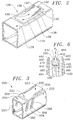
- the contact body 408 has a surface 428 from which a pair of locking lances 430 are struck in cantilevered manner with a longitudinally extending slot 431 therebetween.
- Each of the lances 430 include sides 433 and free end 432 opposite base 434 from which the locking lance 430 extend in cantilevered from.
- At the free end 432 of each locking lance 430 is an upwardly folded and angled tab portion 460.
- the tab portions 460 form a funnel-like opening that is open towards the cantilever end of the locking lance arms 430 for receiving the shoulder of the housing.
- the housing 464 includes a shoulder 466 of generally triangular shape having a forward portion 468 that is received between the lances 430 and separates them in the directions of arrow C ( Figure 5) while depressing them in the direction of arrow B, thereby providing compound resiliency for the locking lances 430.
- Figures 7-10 illustrate a number of possible embodiments of the locking lances that may be especially advantageous and could be used with the embodiments of Figures 1-4.
- Figure 7 illustrates a conventional locking lance 730 struck from surface 728 and cantilevered at base 734 to free end 732 in a linearly extending manner.
- Figure 8 illustrates a locking lance 830 struck from surface 828 and cantilevered from base 834 in a concave upwardly opened manner to free end 832.
- Figure 9 illustrates a locking lance 930 struck outward from surface 928 and cantilevered at base 934 where the locking lances extends initially outward before entering concave section opened downwardly that extends to free end 932 positioned above the surface 928.
- Figure 10 illustrates yet another locking lance 1030 struck from surface 1028 and cantilevered at base 1034 that initially is struck inwards before entering an upwardly open concave section that extends to free end 1032 which is disposed above 1028.
- These locking lance configurations are not meant to be limiting although they may provide additional features that are desirable, such as improved insertion, improved retention, or possibly additional resiliency.
- the present invention enables less structure to be devoted to the locking lance portion of an electrical contact, thereby enabling miniaturization and the addition of additional features that may be desirable in an electrical contact. It is further advantageous that this invention is simple and economical to manufacture and may be incorporated into the normal manufacturing processes of an electrical contact. Finally, it is advantageous that this invention may be incorporated into electrical connectors of different styles and configurations, such as one piece or multiple piece structures, receptacle or pin style contacts of whatever cross-sectional shape is desired.
Landscapes
- Connector Housings Or Holding Contact Members (AREA)
Applications Claiming Priority (2)
| Application Number | Priority Date | Filing Date | Title |
|---|---|---|---|
| GB9417572 | 1994-09-01 | ||
| GB9417572A GB9417572D0 (en) | 1994-09-01 | 1994-09-01 | Electrical contact having improved locking lances |
Publications (2)
| Publication Number | Publication Date |
|---|---|
| EP0700124A2 true EP0700124A2 (de) | 1996-03-06 |
| EP0700124A3 EP0700124A3 (de) | 1996-05-08 |
Family
ID=10760659
Family Applications (1)
| Application Number | Title | Priority Date | Filing Date |
|---|---|---|---|
| EP95113643A Withdrawn EP0700124A3 (de) | 1994-09-01 | 1995-08-30 | Elektrischer Kontakt mit verbessertem Verriegelungsteil |
Country Status (3)
| Country | Link |
|---|---|
| US (1) | US5741162A (de) |
| EP (1) | EP0700124A3 (de) |
| GB (1) | GB9417572D0 (de) |
Cited By (10)
| Publication number | Priority date | Publication date | Assignee | Title |
|---|---|---|---|---|
| FR2751476A1 (fr) * | 1996-07-22 | 1998-01-23 | Whitaker Corp | Borne electrique femelle d'une seule piece pour contact a broche |
| EP0821437A1 (de) * | 1996-07-25 | 1998-01-28 | Sumitomo Wiring Systems, Ltd. | Kontaktbüchsearmatur |
| DE19651120C1 (de) * | 1996-12-09 | 1998-05-07 | Framatome Connectors Int | Kontaktelemente und Steckverbinder, insbesondere für Kabelbäume |
| US5954545A (en) * | 1996-09-30 | 1999-09-21 | The Whitaker Corporation | Electrical contact |
| FR2798228A1 (fr) * | 1999-09-07 | 2001-03-09 | Framatome Connectors Int | Contact electrique et connecteur pour circuit souple |
| CN101924289A (zh) * | 2009-04-28 | 2010-12-22 | 泰科电子公司 | 带有锁定钩的电接触器 |
| DE10320541B4 (de) * | 2002-05-07 | 2012-11-29 | Lear Corp. | Elektrisches Kontaktelement |
| WO2014096891A1 (en) * | 2012-12-21 | 2014-06-26 | Delphi International Operations Luxembourg S.À.R.L. | Assembly of a female terminal which has a contact section divided into two branches and a male terminal |
| EP3035450A1 (de) * | 2014-12-16 | 2016-06-22 | Japan Aviation Electronics Industry, Limited | Verbinder |
| DE102020108278A1 (de) | 2020-03-25 | 2021-09-30 | Lear Corporation | Elektrischer Verbinder und Anschlusssteckersystem |
Families Citing this family (23)
| Publication number | Priority date | Publication date | Assignee | Title |
|---|---|---|---|---|
| US5711067A (en) * | 1996-09-26 | 1998-01-27 | Jenner; Royal | Method of forming electrical connector |
| JP3402435B2 (ja) * | 1997-05-09 | 2003-05-06 | 住友電装株式会社 | プリント基板用コネクタ |
| JP3494857B2 (ja) * | 1997-08-08 | 2004-02-09 | 矢崎総業株式会社 | 接続端子 |
| JP3311997B2 (ja) * | 1998-07-06 | 2002-08-05 | 住友電装株式会社 | コネクタ |
| JP3415133B1 (ja) * | 2002-06-06 | 2003-06-09 | 住友電装株式会社 | 端子金具及びコネクタ |
| JP3885190B2 (ja) * | 2002-11-05 | 2007-02-21 | 矢崎総業株式会社 | 雌端子 |
| DE102007040937B3 (de) * | 2007-08-30 | 2009-01-15 | Tyco Electronics Amp Gmbh | Elektrischer Kontakt |
| US7559779B1 (en) | 2008-05-14 | 2009-07-14 | Cinch Connectors, Inc. | Electrical connector |
| EP2812952A4 (de) | 2012-02-07 | 2015-09-30 | 3M Innovative Properties Co | Zugentlastung für einen elektrostecker |
| CN104170172B (zh) | 2012-02-07 | 2017-06-09 | 3M创新有限公司 | 线材安装电连接器 |
| JP2015511379A (ja) | 2012-02-07 | 2015-04-16 | スリーエム イノベイティブ プロパティズ カンパニー | 電気コネクタ接触端子 |
| US9509089B2 (en) | 2012-02-07 | 2016-11-29 | 3M Innovative Properties Company | Electrical connector latch |
| CN104205507B (zh) | 2012-02-07 | 2017-06-13 | 3M创新有限公司 | 板安装电连接器 |
| JP6204129B2 (ja) * | 2013-09-17 | 2017-09-27 | 矢崎総業株式会社 | 電子部品用端子 |
| JP6405235B2 (ja) * | 2014-12-29 | 2018-10-17 | モレックス エルエルシー | 雌型電気端子、及びコネクタ |
| DE102015209792B4 (de) * | 2015-05-28 | 2017-07-13 | Robert Bosch Gmbh | Kontaktelement |
| DE102016104828A1 (de) * | 2016-03-16 | 2017-09-21 | Te Connectivity Germany Gmbh | Elektrische Kontaktvorrichtung, elektrische Kontakteinrichtung sowie elektrischer Verbinder |
| DE102016110231A1 (de) * | 2016-06-02 | 2017-12-07 | Te Connectivity Germany Gmbh | Kontaktelement und Kontaktsystem |
| CN111262077B (zh) * | 2017-06-23 | 2022-01-14 | 上海莫仕连接器有限公司 | 电源连接器 |
| CN109066158B (zh) * | 2018-08-17 | 2020-01-21 | 凡甲电子(苏州)有限公司 | 电连接器 |
| DE102018121239A1 (de) * | 2018-08-30 | 2020-03-05 | Rosenberger Hochfrequenztechnik Gmbh & Co. Kg | Mehradriges kabel |
| TWI734244B (zh) * | 2019-11-04 | 2021-07-21 | 大陸商東莞訊滔電子有限公司 | 電性端子以及電連接器 |
| US12368262B2 (en) * | 2022-07-01 | 2025-07-22 | Te Connectivity Solutions Gmbh | Electrical connector system |
Family Cites Families (18)
| Publication number | Priority date | Publication date | Assignee | Title |
|---|---|---|---|---|
| NL137554B (de) * | 1966-03-25 | |||
| US3562698A (en) * | 1969-02-27 | 1971-02-09 | Amp Inc | Electrical contact |
| US3789343A (en) * | 1971-06-04 | 1974-01-29 | Shinagawa Automotive Electric | Electrical connector |
| FR2266329A1 (en) * | 1974-03-28 | 1975-10-24 | Labinal | Flat connection pin with sprung securing tongue - has trapezoidal tongue joined to pin by narrow side |
| US3932013A (en) * | 1974-04-08 | 1976-01-13 | Amp Incorporated | Shunt assembly |
| US3966295A (en) * | 1974-06-17 | 1976-06-29 | Elco Corporation | Terminating apparatus for flat conductor cables |
| US4003617A (en) * | 1976-03-17 | 1977-01-18 | Essex International, Inc. | Solderless electrical connector for printed circuit |
| JPS5829900Y2 (ja) * | 1979-04-19 | 1983-06-30 | ヒロセ電機株式会社 | 電気コネクタ |
| US4446684A (en) * | 1982-05-28 | 1984-05-08 | Deere & Company | Cylindrical baler with flare sheets on crop pickup |
| US4620766A (en) * | 1985-04-01 | 1986-11-04 | Molex Incorporated | Terminal with improved retention means |
| GB8812881D0 (en) * | 1988-05-31 | 1988-07-06 | Amp Gmbh | Electrical connector |
| US4907990A (en) * | 1988-10-07 | 1990-03-13 | Molex Incorporated | Elastically supported dual cantilever beam pin-receiving electrical contact |
| DE8908413U1 (de) * | 1989-07-10 | 1989-08-17 | Amp Inc., Harrisburg, Pa. | Elektrischer Verbinder |
| US5131873A (en) * | 1990-09-11 | 1992-07-21 | Molex Incorporated | Female electrical terminal |
| DE9106775U1 (de) * | 1991-06-03 | 1991-07-18 | Amp Inc., Harrisburg, Pa. | Elektrischer Steckkontakt |
| GB9124572D0 (en) * | 1991-11-20 | 1992-01-08 | Amp Gmbh | Electrical terminal having improved retention means |
| US5207603A (en) * | 1992-06-02 | 1993-05-04 | Molex Incorporated | Dual thickness blade type electrical terminal |
| US5342221A (en) * | 1993-01-08 | 1994-08-30 | Molex Incorporated | Keying system for electrical connectors |
-
1994
- 1994-09-01 GB GB9417572A patent/GB9417572D0/en active Pending
-
1995
- 1995-08-30 EP EP95113643A patent/EP0700124A3/de not_active Withdrawn
-
1997
- 1997-04-16 US US08/838,241 patent/US5741162A/en not_active Expired - Fee Related
Non-Patent Citations (1)
| Title |
|---|
| None |
Cited By (17)
| Publication number | Priority date | Publication date | Assignee | Title |
|---|---|---|---|---|
| FR2751476A1 (fr) * | 1996-07-22 | 1998-01-23 | Whitaker Corp | Borne electrique femelle d'une seule piece pour contact a broche |
| US5911603A (en) * | 1996-07-22 | 1999-06-15 | The Whitaker Corporation | Single piece electrical receptacle terminal for mating with a pin contact |
| EP0821437A1 (de) * | 1996-07-25 | 1998-01-28 | Sumitomo Wiring Systems, Ltd. | Kontaktbüchsearmatur |
| US5975964A (en) * | 1996-07-25 | 1999-11-02 | Sumitomo Wiring Systems, Ltd. | Female terminal fitting |
| US5954545A (en) * | 1996-09-30 | 1999-09-21 | The Whitaker Corporation | Electrical contact |
| DE19651120C1 (de) * | 1996-12-09 | 1998-05-07 | Framatome Connectors Int | Kontaktelemente und Steckverbinder, insbesondere für Kabelbäume |
| EP0848453A3 (de) * | 1996-12-09 | 1999-05-19 | Framatome Connectors International | Kontaktelemente und ineinandersteckbare Verbindungselemente, insbesondere für Kabelbäume |
| US5954548A (en) * | 1996-12-09 | 1999-09-21 | Framatome Connectors International | Contact elements and plug-in connectors, in particular for cable harnesses |
| FR2798228A1 (fr) * | 1999-09-07 | 2001-03-09 | Framatome Connectors Int | Contact electrique et connecteur pour circuit souple |
| EP1083628A1 (de) * | 1999-09-07 | 2001-03-14 | F.C.I. - Framatome Connectors International | Elektrischer Kontakt und Verbinder für flexible gedruckte Schaltungen |
| DE10320541B4 (de) * | 2002-05-07 | 2012-11-29 | Lear Corp. | Elektrisches Kontaktelement |
| CN101924289A (zh) * | 2009-04-28 | 2010-12-22 | 泰科电子公司 | 带有锁定钩的电接触器 |
| CN101924289B (zh) * | 2009-04-28 | 2014-10-22 | 泰科电子公司 | 带有锁定钩的电接触器 |
| WO2014096891A1 (en) * | 2012-12-21 | 2014-06-26 | Delphi International Operations Luxembourg S.À.R.L. | Assembly of a female terminal which has a contact section divided into two branches and a male terminal |
| EP3035450A1 (de) * | 2014-12-16 | 2016-06-22 | Japan Aviation Electronics Industry, Limited | Verbinder |
| DE102020108278A1 (de) | 2020-03-25 | 2021-09-30 | Lear Corporation | Elektrischer Verbinder und Anschlusssteckersystem |
| DE102020108278B4 (de) | 2020-03-25 | 2023-12-28 | Lear Corporation | Elektrischer Verbinder und Anschlusssteckersystem |
Also Published As
| Publication number | Publication date |
|---|---|
| US5741162A (en) | 1998-04-21 |
| GB9417572D0 (en) | 1994-10-19 |
| EP0700124A3 (de) | 1996-05-08 |
Similar Documents
| Publication | Publication Date | Title |
|---|---|---|
| US5741162A (en) | Electrical contact having improved locking lances | |
| US5611717A (en) | Miniature anti-fretting receptacle terminal | |
| US5653616A (en) | Electrical receptacle terminal | |
| US4472017A (en) | Tab receptacle terminal | |
| JP4172658B2 (ja) | 高力コンタクト | |
| KR100244733B1 (ko) | 전기콘택트 | |
| EP1215765B1 (de) | Krimpkontaktbüchse | |
| US5980336A (en) | Electrical terminal | |
| US6439935B2 (en) | Female terminal fitting | |
| EP0650224A2 (de) | Elektrischer Kontakt | |
| EP0389955A2 (de) | Doppelt verriegelnder Verbinder für einen elektrischen Endkontakt | |
| US5645458A (en) | Electrical receptacle terminal | |
| KR950021880A (ko) | 저삽입력 리셉터클 단자 | |
| US5624289A (en) | High current receptacle terminal | |
| US6527600B2 (en) | Electrical connector | |
| EP4280389A2 (de) | Elektrische anschlussklemme | |
| JPH11176522A (ja) | コネクタ | |
| GB2044557A (en) | Electrical contact | |
| JP3745318B2 (ja) | 電気コネクタ組立体 | |
| EP0700122A2 (de) | Elektrische Buchse | |
| EP1089387A2 (de) | Modulare elektrische Anschlussbuchse | |
| JP2911020B2 (ja) | 電気接続端子 | |
| US20020055297A1 (en) | Modular female electrical terminal | |
| EP0727843B1 (de) | Asymmetrisches elektrisches Kontaktgehäuse | |
| JP7779829B2 (ja) | 電気雌端子 |
Legal Events
| Date | Code | Title | Description |
|---|---|---|---|
| PUAI | Public reference made under article 153(3) epc to a published international application that has entered the european phase |
Free format text: ORIGINAL CODE: 0009012 |
|
| AK | Designated contracting states |
Kind code of ref document: A2 Designated state(s): DE ES FR GB IT |
|
| PUAL | Search report despatched |
Free format text: ORIGINAL CODE: 0009013 |
|
| AK | Designated contracting states |
Kind code of ref document: A3 Designated state(s): DE ES FR GB IT |
|
| 17P | Request for examination filed |
Effective date: 19961107 |
|
| 17Q | First examination report despatched |
Effective date: 19990322 |
|
| STAA | Information on the status of an ep patent application or granted ep patent |
Free format text: STATUS: THE APPLICATION IS DEEMED TO BE WITHDRAWN |
|
| 18D | Application deemed to be withdrawn |
Effective date: 19990803 |