EP0700143A2 - Wicklung einer Wechselstrommaschine - Google Patents
Wicklung einer Wechselstrommaschine Download PDFInfo
- Publication number
- EP0700143A2 EP0700143A2 EP95202131A EP95202131A EP0700143A2 EP 0700143 A2 EP0700143 A2 EP 0700143A2 EP 95202131 A EP95202131 A EP 95202131A EP 95202131 A EP95202131 A EP 95202131A EP 0700143 A2 EP0700143 A2 EP 0700143A2
- Authority
- EP
- European Patent Office
- Prior art keywords
- coil
- occupying
- winding
- individual coils
- coil sets
- Prior art date
- Legal status (The legal status is an assumption and is not a legal conclusion. Google has not performed a legal analysis and makes no representation as to the accuracy of the status listed.)
- Withdrawn
Links
- 238000004804 winding Methods 0.000 title claims abstract description 84
- 230000005294 ferromagnetic effect Effects 0.000 claims abstract description 21
- 230000005405 multipole Effects 0.000 claims abstract 3
- 238000003780 insertion Methods 0.000 description 17
- 230000037431 insertion Effects 0.000 description 17
- 238000004519 manufacturing process Methods 0.000 description 5
- 238000000034 method Methods 0.000 description 4
- 238000003475 lamination Methods 0.000 description 2
- 230000009467 reduction Effects 0.000 description 2
- 230000006978 adaptation Effects 0.000 description 1
- 230000000903 blocking effect Effects 0.000 description 1
- 230000001419 dependent effect Effects 0.000 description 1
- 230000000694 effects Effects 0.000 description 1
- 239000003302 ferromagnetic material Substances 0.000 description 1
- 238000005304 joining Methods 0.000 description 1
- 239000012811 non-conductive material Substances 0.000 description 1
Images


Classifications
-
- H—ELECTRICITY
- H02—GENERATION; CONVERSION OR DISTRIBUTION OF ELECTRIC POWER
- H02K—DYNAMO-ELECTRIC MACHINES
- H02K3/00—Details of windings
- H02K3/04—Windings characterised by the conductor shape, form or construction, e.g. with bar conductors
- H02K3/28—Layout of windings or of connections between windings
Definitions
- This invention relates to winding patterns on dynamoelectric machines. More specifically, improvements to lap winding patterns in alternating current machines are disclosed which provide for automated manufacturing.
- a winding pattern has efficiencies approaching those achieved with full lap windings.
- the winding pattern allows for automated winding using conventional winding and insertion tooling.
- the winding pattern of the present invention is equally applicable to rotors and stators, and has utility with any number of phases and poles.
- An alternating current machine winding in accordance with the present invention is characterised by the features specified in claim 2 wherein a ferromagnetic structure such as a conventional rotor or stator has a plurality of slots for supporting therein a bottom and top layer of a coil.
- a first number of coil sets are laid in the bottom positions of respective slots thereby resulting in both coil sides of all coils occupying the same layer position.
- a second number of coil sets are laid in respective slots such that all coils on one side of each coil set occupy the same layer position and a portion of the coils on the other side of the coil set occupy the other layer position. The remaining coils not occupying the same layer will occupy the other layer thereby resulting in a coil set that has one side thereof distributed between the two layer positions.
- a portion of the second number of coil sets may have one side thereof occupying one layer position and the other side thereof occupying the other layer position such as is found in conventional full lap winding patterns. Similar to the coil sets wholly in the bottom layer positions, a third number of coil sets are laid in the top positions of respective slots thereby resulting in both coil sides of all coils in the coil sets occupying the same layer position.
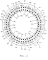
- FIG. 1 a preferred winding pattern for a three phase, four pole alternating current machine is shown.
- the winding pattern is shown occupying the slots of a stator structure 10 although it is to be understood that, while the description herein is provided with reference to stator structures, windings associated with rotor structures are within the purview of the present invention.
- Stator structure 10 is typically formed from laminations of a ferromagnetic material 13 with a non-conductive material therebetween each lamination to reduce the effects of eddy currents through the structure induced by alternating currents in the coils supported thereby.
- the view of the stator shown in Figure 1 is cross-sectional therethrough.
- Slots in the stator structure are labeled 1 through 48 adjacent each slot around the periphery of the stator structure.
- the coil sets are designated by two character alpha-numeric symbols, the first character thereof designating which of the three phases the coil set corresponds to A, B, or C, and the second character thereof designating the coil set 1-4.
- Figure 2 which shows four coil sets each having three phase inputs A, B and C.
- Figure 2 also labels each coil set with a (+) designating the phase input A, B or C common to each coil set for each respective phase and a (-) designating the common node between and among all coil sets regardless of phase.
- stator slots 1 through 4 are occupied by one side of all individual coils making up one side of the coil set A1.
- the other side of the individual coils making up the other side of the coil set A1 are likewise in the bottom layer position of stator slots 11 through 14.
- This is described herein as a flat coil set in as much as all coils occupy the same layer position of respective slots.
- Each coil set comprises a distributed coil set; that is to say the sides of the individual coils of a coil set are spread out to occupy several adjacent stator slot positions.
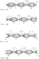
- FIG 5A a view of the various coil sets as if the stator structure were opened up and laid out flat is shown. The numerical designations correspond to the slot number in the stator.
- coil set A1 can be seen having one side of all individual coils making up one side of the coil set occupying slots 1 through 4.
- the other side of all individual coils making up the other side of the coil set occupies slots 11 through 14.
- the present embodiment in a three phase, four pole alternating current machine, the number of slots per pole equals 12.
- This is a preferred arrangement for reasons well known in the art including that the resultant electromotive force induced in the winding and the magnetomotive force produced by the winding is distributed closer sinusoidally and has greatly reduced harmonic content from that of a full pitch winding.
- the geometric nature of a fractional pitch winding is such that the number of slots between the innermost coils of any coil set is a fractional multiple of the number of individual coils making up a coil set.
- the number of slots between the two innermost coils thereof is equal to 6 which is a fractional multiple of the number of individual coils in a coil set (i.e. 4x1.5). Therefore, where coil sets occupy the same layer position for both sides of all of its coils, eventually a fractional (with respect to the number of individual coils in a coil set) number of unoccupied layer positions will result.
- opposite coil sides of all coil sets have been fully lapped such that similar sides of different coil sets are placed in one of the layer positions and the opposite' sides are placed in the other of the layer positions. These type of coil sets have been referred to in the art as lapped coil sets.
- the present invention utilizes a plurality of flat coil sets disposed in the bottom layer position of the stator slots.
- the number of coil sets which may be positioned thusly is dependent upon the number of phases in the machine, the number of poles and the coil pitch.
- four pole machine it can be seen in Figure 1 that three flat coil sets A1, C1 and B3 occupy bottom layer positions of the stator slots. It follows then that these three coil sets are, as a group, first to be wound and inserted into the respective stator slots.
- the first inserted coil sets are also illustrated in Figure 6A which demonstratively shows coil placement relative to the slots as if the stator slots were laid out flat and viewed radially outward from the vantage point of the geometric center of the stator structure. For clarity, only certain of the stator slots are numbered.
- conventional automated winding tooling is employed to reduce the time and cost associated with producing machines having the winding pattern according to the present invention.
- the winding process begins by winding the individual coils comprising the coil sets on a conventional shed flyer winder. Each individual coil may be wound from one or more turns of the wire and in the present embodiment a four turn coil is utilized. Once an individual coil is wound on the shed flyer winder, it is then transferred to a set of fingers on a transfer tool. The transfer tool is indexed one slot position and a next individual coil of the coil set is wound and transferred to another set of fingers. The steps are repeated until the individual coils in the coil set are completed.
- the coil groups in the first winding and insertion phase are all wound and placed on the transfer tooling in this manner. In the present preferred winding pattern, three coil sets are wound and placed on the transfer tool in this first phase.
- the transfer tool is next removed from the winder and placed on a coil insertion machine.
- the fingers of the transfer tool are aligned with the blades of an insertion tool and the coil sets are transferred thereto.
- the stator is placed on the insertion tool loading fixture such that the slots are aligned for accepting the coil sets therein.
- the loading fixture allows the stator to be indexed for subsequent insertion phases.
- insulative wedges are also placed therein in a well known manner to isolate phases and layers.
- each of the six coil sets C2, B2, A4, B1, A3 and C3 is characterized by all individual coils on one side of the respective coil set occupying either the bottom or top layer positions of the stator slots with the remaining individual coils on the other side of the respective coil set being split between the bottom and top layer positions of the stator slots.
- These coil sets are designated kinked coils herein. These kinked coils differ from prior art coil sets of conventional lap winding topology in that one of the sides thereof occupies both bottom and top slot positions.
- Three of the six kinked coil sets, those designated C2, B2 and A4 are characterized by one complete side thereof occupying the bottom layer position of the respective stator slots.
- coil sets C2, B2 and A4 are, as a group, second to be wound and inserted into the respective stator slots. This second inserted set of coils is also illustrated in Figure 6B. Again, only certain of the slots are labeled for clarity.
- the winding process for coil sets C2, B2 and A4 is performed as previously described above with reference to the first three coil sets.
- the stator having been indexed from the previous insertion phase is positioned to accept the second three coil sets.
- this insertion phase it is noted that the two outermost individual coils of one of the sides of each coil set will lap two outermost individual coils of one of the sides of each coil set previously inserted and occupying the bottom layer position of common stator slots.
- the remaining individual coils of each coil set are drifted to occupy the bottom layer position of the respective stator slots.
- Coil sets B1, A3 and C3 are characterized by one complete side thereof occupying the top layer position of the respective stator slots. Coil sets B1, A3 and C3 are therefore the third coil sets to be wound and inserted into the respective stator slots. The third inserted set of coils is also illustrated in Figure 6C.
- the winding process for coil sets B1, A3 and C3 is performed as previously described.
- the stator having been indexed from the previous insertion phase is positioned to accept the third three coil sets.
- this insertion phase it is noted that the two outermost individual coils of one of the sides of each coil set will occupy the bottom layer position of the stator between previously inserted and bottom layer position occupying coils.
- the remaining individual coils of each of these three coil sets occupies the top layer position of the respective stator slots.
- the final three coil sets are characterized by all individual coils on both sides of each coil set occupying the top layer position of the respective stator slots. These coil sets are of course the fourth and final coil sets to be wound and inserted into the respective stator slots. The fourth inserted set of coils is also illustrated in Figure 6D.
- stator having been indexed from the previous insertion phase is positioned to accept the final three coil sets in the top layer positions of the respective slots. After this final insertion phase, the stator moves on to conventional blocking and lacing operations well known to those skilled in the art.
- the winding pattern of the present invention when compared to a conventional full lap winding pattern exhibits the same slot placement of the individual coils in the coil sets with respect to circumferential position but exhibits different radial positioning (i.e. bottom and top layer positioning).
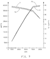
- Figure 7 illustrates a comparison of peak output power and output torque characteristics for a conventional full lap winding motor versus that for a motor wound with the present inventive pattern.
- the solid lines represents data for a conventional full lap wound motor and the broken line represent data for an equivalent phase and pole motor wound with the present inventive motor winding pattern.
- Curve 71 and 73 are torque output curves read against the right hand legend
- curves 75 and 77 are peak power output curves read against the left hand legend.
- Maximum deviation of the output and torque of the kinked winding motor across the full range of motor operation is approximately only 0.8%, and the average motor efficiency reduction from that of a conventional full lap wound machine is approximately only 0.5%.
- the kinked coil sets of the present invention are illustrated in Figures 3 and 4 which demonstrate the inventive winding pattern in three phase, eight pole and three phase, two pole machines respectively.
- the stator has 48 slots labeled accordingly.
- the eight pole machine of Figure 3 has 24 coil sets in total; or, eight coil sets per each of the three phases.
- the two pole machine of Figure 4 has 6 coil sets in total; or, two coil sets per each of the three phases.
- the coil sets in both Figures are again designated by two character alpha-numeric symbols in the same manner as those in Figure 1.
- the (+) and (-) designation that follows the coil set labels again designates the relative current direction in a respective coil set winding.
- An exemplary flat coil set in the bottom layer positions of the stator slots of Figure 3 is labeled A1.
- Bottom layer slot positions in slots 1 and 2 are occupied by one side of the coil set A1 and bottom layer slot positions in slots 6 and 7 are occupied by the other side of the coil set A1.
- All coil sets with both sides thereof in the bottom layer slot positions (A1, C1, B3, A5, C5, B7) are, again, the first as a group to be wound and inserted whether manually or automatically.
- Twelve kinked coil sets are next inserted in two subgroups.
- the first subgroup of kinked coils wound and inserted comprises those coil sets that have one side thereof in the bottom layer position (C8, B2, A4, C4, B6 and A8).
- the second subgroup of kinked coils wound and inserted comprises the remaining kinked coils and those with one side thereof in the top layer position (B1, A3, C3, A7 and C7).
- the flat coil sets with both coil sides thereof occupying the top layer positions of the stator slots (A2, C2, B4, A6, C6 and B6) are wound and inserted.
- An exemplary flat coil set in the bottom layer positions of the stator slots of Figure 4 is labeled A1.
- Bottom layer slot positions in slots 1-8 are occupied by one side of the coil set A1 and bottom layer slot positions in slots 21-28 are occupied by the other side of the coil set A1.
- All coil sets with both sides thereof in the bottom layer slot positions (A1 and B2) are, again, the first as a group to be wound and inserted whether manually or automatically.
- Two kinked coil sets (C1 and A2) are next wound and inserted.
- one of the two kinked coil sets (C1) has one side thereof in the bottom layer position
- the other of the two kinked coil set (A2) has one side thereof in the top layer position.
- K Kinked Coil Sets
- A Slots Spanned per Coil Set
- B Individual Coils per Coil Set
- A is equal to 14 (see coil set A1 for example spans from slot 1 to slot 14);
- B is equal to 4 (see coil A1 for example occupies four slots per side, thus four coils);
- C equals 48. Reducing the expression yields a value for K of 6 which coincides with the number of kinked coils.
- some of the kinked coil sets may have one side thereof fully occupying one layer position and the other side thereof fully occupying the other layer position such as is found in conventional full lap winding patterns.
- Such a configuration is known having coil sets with a coil span, or slot pitch, between the two sides of an individual coil equal to ten.
- the number of slots per pole equals 6. Therefore, the pitch of the winding is 5/3 (i.e. 10/6). This is known as an overcoiling arrangement.
- the number of individual coils in this embodiment is chosen to be three and results in a winding pattern suitable for full lapped application.
- the full lapped winding is undesirable inasmuch as it is a very manual labor intensive pattern not producible on high speed automated production equipment.
- the present invention provides a winding pattern suitable for adaptation to automated winding equipment.
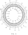
- Figure 5 shows such a winding pattern for a four phase, eight pole machine.
- a first group of coil sets A1, B1, C1 and D1 are flat coil sets disposed in the bottom layer position of the stator slots.
- a second group of coil sets A2, B2, C2, D2, A3, B3, C3 and D3 have individual coils of one side of each coil set occupying either the top or the bottom layer positions of the stator slots with the remaining individual coils of the other side of each coil set either split between the bottom and top layer positions of the stator slots (A2, B2, C2, B3, C3, D3) or fully occupying the other layer position (D2, A3).
- a third group of coil sets A4, B4, C4 and D4 are flat coil sets disposed in the top layer position of the stator slots.
- the first winding and insertion phase will be performed for coil sets A1, B1, C1 and D1 as all coils on both sides of these coil sets are drifted all the way back to the bottom slot position. Since in this overcoil configuration coil sets A1 and D1 overlap (but do not occupy the same slots), coil sets A1 and D1 may require end turns which bypass each other (longitudinally with respect to the stator) to prevent interferences thereat. While this is never optimal from a performance standpoint, the benefits of automated winding and fewer overall winding and insertion phases may outweigh the relatively small efficiency reductions occasioned thereby.
- coil sets A2, B2, C2 and D2 are wound and inserted since all individual coils of one side thereof occupies the bottom slot positions which, of course, are to be first occupied. Since coil sets A2 and D2 overlap, their end turns may also need to bypass one another. Coil set A3, B3, C3 and D3 are next wound and inserted thus completing occupation of the bottom layer positions of the stator slots. Again, coil sets A3 and D3 are overlapping so bypassing of the end turns may be required. Finally, coil sets A4, B4, C4 and D4 (with similar end turn bypass provisions for A4 and D4) are wound and inserted thus completing the automated winding and insertion of the four phase, eight pole machine in as few as four winding and insertion phases.
Landscapes
- Engineering & Computer Science (AREA)
- Power Engineering (AREA)
- Windings For Motors And Generators (AREA)
Applications Claiming Priority (2)
| Application Number | Priority Date | Filing Date | Title |
|---|---|---|---|
| US29997894A | 1994-09-02 | 1994-09-02 | |
| US299978 | 1994-09-02 |
Publications (2)
| Publication Number | Publication Date |
|---|---|
| EP0700143A2 true EP0700143A2 (de) | 1996-03-06 |
| EP0700143A3 EP0700143A3 (de) | 1997-02-12 |
Family
ID=23157139
Family Applications (1)
| Application Number | Title | Priority Date | Filing Date |
|---|---|---|---|
| EP95202131A Withdrawn EP0700143A3 (de) | 1994-09-02 | 1995-08-03 | Wicklung einer Wechselstrommaschine |
Country Status (1)
| Country | Link |
|---|---|
| EP (1) | EP0700143A3 (de) |
Cited By (2)
| Publication number | Priority date | Publication date | Assignee | Title |
|---|---|---|---|---|
| US20120019083A1 (en) * | 2010-07-23 | 2012-01-26 | Ahmed Mostafa Elantably | High power-density, high efficiency, non-permanent magnet electric machine |
| EP2270962A4 (de) * | 2009-03-27 | 2017-03-29 | Huazhong University of Science and Technology | Bürstenloser doppelt angetriebener motor für einen wickelrotor |
Family Cites Families (1)
| Publication number | Priority date | Publication date | Assignee | Title |
|---|---|---|---|---|
| KR940001176B1 (ko) * | 1990-07-19 | 1994-02-16 | 가부시끼가이샤 도시바 | 3상 전기자 권선 |
-
1995
- 1995-08-03 EP EP95202131A patent/EP0700143A3/de not_active Withdrawn
Non-Patent Citations (1)
| Title |
|---|
| None |
Cited By (4)
| Publication number | Priority date | Publication date | Assignee | Title |
|---|---|---|---|---|
| EP2270962A4 (de) * | 2009-03-27 | 2017-03-29 | Huazhong University of Science and Technology | Bürstenloser doppelt angetriebener motor für einen wickelrotor |
| US20120019083A1 (en) * | 2010-07-23 | 2012-01-26 | Ahmed Mostafa Elantably | High power-density, high efficiency, non-permanent magnet electric machine |
| US8310115B2 (en) * | 2010-07-23 | 2012-11-13 | General Electric Company | High power-density, high efficiency, non-permanent magnet electric machine |
| US8587164B2 (en) | 2010-07-23 | 2013-11-19 | General Electric Company | High power-density, high efficiency, non-permanent magnet electric machine |
Also Published As
| Publication number | Publication date |
|---|---|
| EP0700143A3 (de) | 1997-02-12 |
Similar Documents
| Publication | Publication Date | Title |
|---|---|---|
| US5376852A (en) | Three-phase armature winding | |
| US8122590B2 (en) | Manufacturing methods for a triple layer winding pattern | |
| US7155805B2 (en) | Method for making stator of rotary electric machine | |
| US8294324B2 (en) | Winding arrangement for stator of rotating machinery | |
| US4833356A (en) | Compact connections for interdispersed armature winding | |
| CN105896780B (zh) | 三相交流电动机 | |
| US20230179054A1 (en) | Stator having wave-winding coil structure, three-phase ac motor equipped with same, and method for producing stator | |
| US7386931B2 (en) | Method of forming cascaded stator winding | |
| EP1344296B1 (de) | Spulenwicklungsanordnung für armaturen | |
| JP4177462B2 (ja) | 回転電気装置用の2個の切り込み面内への巻線方法 | |
| US6590309B2 (en) | Stator assembly for an electromechanical machine | |
| US6943477B1 (en) | Stator of rotary electric machine and method for making the same | |
| US20230127155A1 (en) | Stator having coil structure of distributed winding, and three-phase ac electric motor comprising said stator | |
| CN214412445U (zh) | 一种电机定子绕组、电机定子及电机 | |
| EP0700143A2 (de) | Wicklung einer Wechselstrommaschine | |
| JP5163255B2 (ja) | 回転電機の固定子 | |
| CN218888246U (zh) | 一种扁线电机定子及电机 | |
| US12463474B2 (en) | Stator for rotating electrical machine and method for manufacturing stator for rotating electrical machine | |
| CN216819543U (zh) | 一种定子及电机 | |
| CN218829313U (zh) | 定子绕组、定子结构和扁线电机 | |
| CN111478484A (zh) | 一种电机定子及电机 | |
| CN212033858U (zh) | 一种电机定子及电机 | |
| JP7420584B2 (ja) | 三相電動機及びコイル巻線方法 | |
| EP0152222B1 (de) | Linearmotor | |
| JPH04251537A (ja) | 回転電機の電機子 |
Legal Events
| Date | Code | Title | Description |
|---|---|---|---|
| PUAI | Public reference made under article 153(3) epc to a published international application that has entered the european phase |
Free format text: ORIGINAL CODE: 0009012 |
|
| AK | Designated contracting states |
Kind code of ref document: A2 Designated state(s): DE FR GB |
|
| PUAL | Search report despatched |
Free format text: ORIGINAL CODE: 0009013 |
|
| AK | Designated contracting states |
Kind code of ref document: A3 Designated state(s): DE FR GB |
|
| STAA | Information on the status of an ep patent application or granted ep patent |
Free format text: STATUS: THE APPLICATION IS DEEMED TO BE WITHDRAWN |
|
| 18D | Application deemed to be withdrawn |
Effective date: 19970813 |