EP0700203A1 - Appareil d'enregistrement de signaux vidéo utilisant un écran tactile - Google Patents
Appareil d'enregistrement de signaux vidéo utilisant un écran tactile Download PDFInfo
- Publication number
- EP0700203A1 EP0700203A1 EP95306175A EP95306175A EP0700203A1 EP 0700203 A1 EP0700203 A1 EP 0700203A1 EP 95306175 A EP95306175 A EP 95306175A EP 95306175 A EP95306175 A EP 95306175A EP 0700203 A1 EP0700203 A1 EP 0700203A1
- Authority
- EP
- European Patent Office
- Prior art keywords
- video signal
- image data
- pressed
- display device
- recording
- Prior art date
- Legal status (The legal status is an assumption and is not a legal conclusion. Google has not performed a legal analysis and makes no representation as to the accuracy of the status listed.)
- Granted
Links
Images




Classifications
-
- H—ELECTRICITY
- H04—ELECTRIC COMMUNICATION TECHNIQUE
- H04N—PICTORIAL COMMUNICATION, e.g. TELEVISION
- H04N5/00—Details of television systems
- H04N5/76—Television signal recording
- H04N5/765—Interface circuits between an apparatus for recording and another apparatus
- H04N5/77—Interface circuits between an apparatus for recording and another apparatus between a recording apparatus and a television camera
-
- H—ELECTRICITY
- H04—ELECTRIC COMMUNICATION TECHNIQUE
- H04N—PICTORIAL COMMUNICATION, e.g. TELEVISION
- H04N23/00—Cameras or camera modules comprising electronic image sensors; Control thereof
- H04N23/60—Control of cameras or camera modules
- H04N23/63—Control of cameras or camera modules by using electronic viewfinders
- H04N23/631—Graphical user interfaces [GUI] specially adapted for controlling image capture or setting capture parameters
-
- H—ELECTRICITY
- H04—ELECTRIC COMMUNICATION TECHNIQUE
- H04N—PICTORIAL COMMUNICATION, e.g. TELEVISION
- H04N5/00—Details of television systems
- H04N5/76—Television signal recording
- H04N5/765—Interface circuits between an apparatus for recording and another apparatus
Definitions
- the present invention relates to a video apparatus that is suitable for a united VTR with a camera and the like including a large size LCD panel (liquid crystal display panel).
- LCD panel liquid crystal display panel
- title producer for a video camera
- an image such as characters, graphics and the like
- the drafted paper is then filmed to generate a title image.
- the present invention provides a video apparatus that can insert easily the title into the video picture during, for example, a period while the video picture is being taken.
- a video apparatus comprising: a display device; position detection means provided on a display screen of said display device for detecting a position at which said display screen is pressed by a user; image data forming means for forming image data in accordance with the pressed position detected by said position detection means; and superimposing means for superimposing the image data formed by said image data forming means on a video signal to be applied to said display device.
- a second aspect of the invention provides a video apparatus, comprising: a display device; position detection means provided on a display screen of said display device for detecting a position at which said display screen is pressed by a user; superimposing means for superimposing operation key screen data on a video signal to be applied to said display device; and operation signal generation means for generating an operation signal corresponding to an operation key displayed on the pressed position detected by said position detection means.
- a third aspect of the invention provides a video signal recording apparatus, comprising: a display device; position detection means provided on a display screen of said display device for detecting a position at which said display screen is pressed by a user; image data forming means for forming image data in accordance with the pressed position detected by said position detection means; superimposing means for superimposing the image data formed by said image data forming means on a video signal to be applied to said display device; and recording means for recording the video signal on which the image data is superimposed by said superimposing means.
- a fourth aspect of the invention provides a united VTR with camera for recording a video signal from a camera section, comprising: a display device; position detection means provided on a display screen of said display device for detecting a position at which said display screen is pressed by a user; image data forming means for forming image data in accordance with the pressed position detected by said position detection means; superimposing means for superimposing the image data formed by said image data forming means on a video signal to be applied to said display device; a camera section for converting a light from a subject into a video signal and outputting it; and recording means for recording the video signal from said camera section on which the image data is superimposed by said superimposing means.
- the image data such as the title image
- the image data can be produced in easy by pressing the display screen of the display device. Since the produced image data is superimposed on the video signal and applied to the display device, the image data can be formed while confirming the formed image with the display screen.
- the invention displays on the display screen the operation keys necessary only for the next operation, so that the contents of the display screen is not complex and an operationality for users can be improved.
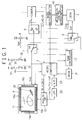
- a camera section 1 comprises an image pick-up lens, an image pick-up device, an image signal processing circuit and the like and produces a pick-up video signal SVi.
- a deck section 2 comprises a rotation head device, a record/replay processing circuit and the like and records and replays a video signal on or from a recording track of a magnetic tape.
- the operation modes of the deck section 2 is controlled by a mechanical control microprocessor (microcomputer) 40 under control of a mode microprocessor (microcomputer) 4.
- the mode microprocessor 4 is connected to a microprocessor (microcomputer) 3 that receives a master clock signal CLK, a horizontal synchronous signal HD and a vertical synchronous signal VD from the camera section 1.
- the pick-up video signal SVi from the camera section 1 is applied to a fixed contact a of a switch 5 as well as a fixed contact a of a switch 6.
- a fixed contact b of the switch 5 receives a replayed video signal Svp from the deck section 2.
- An output signal from the switch 5 is applied to a fixed contact b of a switch 7.
- a variable resistor 8 is used to set a white level signal and is connected between a power supply voltage contact receiving a DC voltage Vs and ground.
- a white level signal Swh from a movable contact of the variable resistor 8 is applied to a fixed contact a of the switch 7 and a fixed contact 6 of the switch 6.
- the output signal from the switch 6 is a recording video signal SVr that is applied to the deck section 2.
- the output signal from the switch 7 is a display video signal SVd being applied to a color LCD panel (color liquid crystal display panel) 9.
- the mode microprocessor 4 controls the switch 5 where a movable contact is connected to the contact b for the replay period and is connected to the contact a for the other period.
- the switching operations of the switches 6 and 7 are controlled by a RAM controller 10 that will be discussed hereinafter.
- a resistance film type touch panel 11 is mounted on a display screen of the LCD panel 9.
- Figure 2 shows a configuration of the touch panel 11.
- a glass substrate 12 and a film sheet 13 are supported by a spacer 14 at the peripheral edge portions such that the glass substrate 12 faces the film sheet 13.
- ITO (Indium Tin Oxide) films 15 and 16 as transparent resistance films are coated on the opposite surfaces of the glass substrate 12 and the film sheet 13.
- a plurality of dot spacers 17 are provided on the ITO film 15 coated on the surface of the glass substrate 12 at a constant interval.
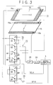
- FIG 3 shows a position detection system of the touch panel 11. Electrodes 16a and 16b (not shown in Figure 2) made of carbon or the like are provided on both edge portions of the ITO film 16 formed on the film sheet 13 surface in a horizontal (X) direction and electrodes 15a and 15b (not shown in Figure 2) made of carbon or the like are provided on both edge portion of the ITO film 15 formed on the glass substrate 12 in a vertical (Y) direction.
- An analog switch section 20 applies predetermined voltages to the electrodes 15a, 15b, 16a and 16b under control of the microcomputer 3 in order to detect the X and Y coordinates.
- the electrode 15a is connected to a fixed contact a of a switch 23 in the analog switch section 20 and a fixed contact b and a movable contact of the switch 23 are grounded.
- the electrode 15b is connected to a movable contact of a switch 25 in the analog switch section 20, a fixed contact b of the switch 23 is grounded and a fixed contact a thereof is connected to a movable contact of a switch 22.
- the electrode 16a is coupled with a fixed contact b of a switch 24 in the analog switch section 20 and a fixed contact a and a movable contact of the switch 24 are grounded.
- the electrode 16b are connected to movable contacts of switches 21 and 26 in the analog switch section 20.
- a fixed contact a of the switch 26 is electrically floated and a fixed contact b thereof is connected through a resistor 27 having a relatively high resistance to a power supply terminal receiving the DC voltage Vs.
- the resistance vale between the electrodes 16a and 16b for the ITO film 16 and the resistance value between the electrodes 15a and 15b for the ITO film 15 are respectively a few hundreds ohms, but the resistance value of the resistor 27 is, for example, 47 K ohms.
- a fixed contact b of the switch 21 and a fixed contact a of the switch 22 are connected to a power terminal receiving the DC voltage Vs.
- a signal from a fixed terminal a of the switch 21 or a fixed terminal b of the switch 22 is an output signal of the analog switch section 20 that is applied through a lowpass filter (LPF) 28 to an A/D converter 29.
- the digitized signal by the A/D converter 29 is applied to the microcomputer 3.
- the lowpass filter 28 eliminates noise produced by a back light (fluorescent light) for the LCD panel 9.
- the switches 21 through 24 consisting of the analog switch section 20 is controlled by a selection signal SELA from the microcomputer 3 wherein the fixed contacts a are selected when the selection signal SELA is a high level "H” and the fixed contacts b are selected when the selection signal SELA is a low level "L”.
- the switches 25 and 26 consisting of the analog switch section 20 is controlled by a selection signal SELB from the microcomputer 3 wherein the fixed contacts a are selected when the selection signal SELB is the high level "H” and the fixed contacts b are selected when the selection signal SELB is the low level "L".
- the condition of the analog switch selection 20 is changed to one of three modes, namely, an X coordinate sampling mode, a Y coordinate sampling mode and a pen-on/off judgment mode, under control of the selection signals SELA and SELB from the microcomputer 3.
- the X coordinate sampling mode will be discussed first.
- the selection signal SELA is the low level “L” and the selection signal SELB is the high level “H” so that the switches 21-24 select the fixed contacts b and the switches 25 and 26 select the fixed contacts a.
- the electrode 16a is grounded, the electrode 16b receives the DC voltage Vs and the voltage Vx obtained from the electrode 15b is applied to the microcomputer 3 via the lowpass filter 28 and the A/D converter 29 as shown in Figure 4 (the ITO films 15 and 16 are represented by resistors equivalently).
- the position pressed by hand-held pointing implement such as a pen 30 shown by an arrow P is a position where the ITO film 16 is internally divided by a:b in the X direction
- the voltage Vx derived from the electrode 15b is Vs x a/(a+b).
- This voltage Vx is the X coordinate value (X address data) of the pressed position and applied to the microcomputer 3.
- both the selection signals SELA and SELB are the high level "H" and the switches 21-26 select the fixed contacts a.
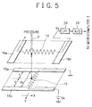
- this mode cause the electrode 15a to be grounded, the electrode 15b to receive the DC voltage Vs and a voltage Vy derived at the electrode 16b to be applied to the microcomputer 3 via the lowpass filter 28 and the A/D converter 29 as shown in Figure 5 (ITO films 15 and 16 are represented as resistors equivalently).
- the voltage Vy generated at the electrode 16b is Vs x c/(c+d). This voltage Vy is applied as the Y coordinate value (Y address data) to the microcomputer 3.
- the pen-on/off mode will be discussed.
- the selection signal SELA is the high level “H” and the selection signal SELB is the low level “L”
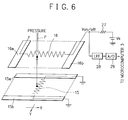
- the switches 21-24 select the fixed contacts a and the switches 25 and 26 select the fixed contacts b. Therefore, according to this mode, the electrodes 15a and 15b are grounded, the electrode 16b receives the DC voltage Vs via the resistor 27 and a voltage Von/off derived from the electrode 16b is applied as the pen-on/off judgment data to the microcomputer 3 through the lowpass filter 28 and the A/D converter 29 as shown in Figure 6 (the ITO films 15 and 16 are represented by resistors equivalently).
- the microcomputer 3 selects alternately the X coordinate sampling mode and the Y coordinate sampling mode and selects the pen-on/off judgment mode before and after each the sampling mode.
- the X coordinate value and the Y coordinate value derived at each the sampling mode are judged to be valid.
- this process prevents the X and Y coordinate error values based on a poor pressure of the pen 3 from being detected.
- the dot data of one screen can be written in a static RAM (SRAM) 31.
- a RAM controller 10 controls to write and read the dot data in and from the SRAM 31 under control of the microcomputer 3.
- the RAM controller 10 receives the master clock CLK, the horizontal synchronous signal HD and the vertical synchronous signal VD from the camera section 1.
- the master clock CLK, the horizontal synchronous signal HD and the vertical synchronous signal VD are applied to the other blocks (not shown) if necessary.
- a series circuit of a resistor 32 and the connection switch 33 is inserted between the power supply terminal and ground and a voltage Vm at a common junction of the resistor 32 and the switch 33 is applied as mode setting data to the microcomputer 3.
- the voltage Vm is the high level "H” that represents the pen input mode.
- the switch 33 is the on condition, the voltage Vm is the low level "L” that represents the key operation mode.
- a series circuit of a resistor 34 and a connection switch 35 is connected between the power supply terminal and ground and a voltage Vc at a common junction of the resistor 34 and the switch 35 is applied as clear data to the microcomputer 3.
- Vc the voltage at a common junction of the resistor 34 and the switch 35 is applied as clear data to the microcomputer 3.
- the switch 35 is turned on, the voltage Vc is the low level "L”. Then, in the pen input mode, the RAM controller 10 clears the dot data in the SRAM 31 under control of the microcomputer 3.
- the address data (x,y) for the SRAM 31 is produced and adjusted such that the X coordinate value Vx and the Y coordinate value Vy applied to the microcomputer 3 by the A/D converter 29 match the picture angle of the LCD panel 9 and a dot appears at a position where the pen 30 is pressed. Then, the microcomputer 3 applies the address data (x,y) to the RAM controller 10 and the dot data is written in the corresponding address location of the SRAM 31.
- the dot data is written in the SRAM 31 in accordance with the address data (x,y) that corresponds to the operation key display stored in a key display table (not shown) in the microcomputer 3.
- the address data (x,y) that corresponds to the operation key display stored in a key display table (not shown) in the microcomputer 3.
- the RAM controller 10 reads the dot data from the SRAM 31 in synchronism with the pick-up video signal SVi and applies it to the microcomputer 3 under control of the microcomputer 31.
- the RAM controller 10 controls the selection of the switch 7 under control of the microcomputer 3. Since the switch 7 selects the fixed contact a in response to the dot data, for example, the white level signal Swh corresponding to the dot data is superimposed on the pick-up video signal SVi in order to generate the display video signal SVd. Therefore, the LCD panel 9 displays the superimposed result where the image, such as characters and graphics, produced by the press operation of the pen 30 to the touch panel 11 is superimposed on, for example, the pick-up video signal SVi.
- the RAM controller 10 controls the selection of the switch 6 under control of the microcomputer 3.
- the switch 6 selects the fixed contact b in response to the dot data, so that the white level signal Swh corresponding to the dot data is superimposed on the pick-up video signal SVi in order to produce the recording video signal SVr.
- the deck section 2 can record the recording video signal SVr that is generated by superimposing the white signal Swh corresponding to the image, such as the characters and graphics, on the pick-up video signal SVi.
- the RAM controller 10 When the key operation mode is set, the RAM controller 10 reads the dot data from the SRAM 31 in synchronism with the pick-up video signal SVi and applies it to the microcomputer 3 under control of the microcomputer 3.
- the RAM controller 10 controls the selection of the switch 7 under control of the microcomputer 3. Since the switch 7 selects the contact a in response to the dot data, the white level signal Swh corresponding to the dot data is superimposed on, for example, the pick-up video signal SVi in order to generate the display video signal SVd. Therefore, the LCD panel 9 displays the superimposed result where the image of the operation key is superimposed on, for example, the picture video signal SVi.
- the microcomputer 3 recognizes the pressed operation key in accordance with the X coordinate value and the Y coordinate value applied from the A/D converter 29.
- the microcomputer 3 applies the mode signal corresponding to the operation key into the mode microcomputer 4, and the mode microcomputer 4 informs the operation of the deck section 2 to the mechanical control microcomputer 40 or controls the selection of the switch 5. If the key operation mode is set, the switch 6 remains to select the contact a and the deck section 2 receives the pick-up video signal SVi as the recording video signal Svr.
- Figure 8 shows a display example on the LCD panel 9 in the key operation mode.
- the operation corresponding to the pressed operation key would be performed.
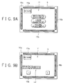
- the LCD panel 9 displays operation keys as shown in Figure 9A in order to select additional functions, such as a brightness adjustment, a color adjustment or a volume adjustment (audio system is not shown).
- Figure 9B shows a display example when the display area of the brightness adjustment key is pressed.
- the display includes operation keys (plus key and minus key) for adjusting the brightness and the adjustment level LV. If a portion of a return key is pressed in the screen of Figures 9A and 9B, the previous screen can be recalled.
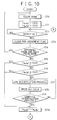
- a step ST0 the SRAM 31 is cleared.
- the step ST1 changes the one field prior address data (x0,y0) to (0,0) and changes the current address data (xN, yN) to (0,0).
- the step ST2 judges whether the vertical synchronous signal VD is detected or not. If the vertical synchronous signal VD is detected, the process advances to a step ST3 where a pen judgment flag is cleared.
- the next step ST4 determines whether the setting condition of the pen input mode or the key operation mode is different from the condition of one field prior mode (i.e., the mode prior by one field with respect to the current mode). If the current mode is different from the one field prior mode, the process returns to the step STO. If the current mode is the same as the one field prior mode, the process advances to a step ST5.
- the step ST5 determines whether the one field prior address data (x0,y0) is (0,0) or not. If (x0,y0) is not (0,0) in the step ST5, the process goes to the step ST6 where the current address data (xN,yN) is judged to be (0,0) or not.
- step ST7 executes a linear interpolation.
- a line between (x0,y0) and (xN,yN) is process by the linear interpolation.
- the dots are written in the SRAM 31 at the address data (x0,y0) and the address data produced by the liner interpolation.
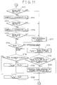
- a step ST11 judges whether the result of the pen-on/off judgment mode is the pen-on condition or the pen-off condition. If the pen-on condition is judged in the step ST11, a step ST12 obtains the X coordinate value Vx for the X coordinate sampling mode (refer to Figure 4).
- a step ST 13 determines whether the pen-on/off judgment mode is in the pen-on condition or the pen-off condition. If the step ST13 is in the pen-on condition, a step ST14 obtains the Y coordinate value Vy for the Y coordinate sampling mode (refer to Figure 5). A step ST15 determines whether the pen-on/off judgment mode is in the pen-on condition or the pen-off condition.
- step ST15 is in the pen-on condition
- the process advances to a step ST16.
- step ST16 detects the key operation mode
- the address data is read from the key display table in the microcomputer 3 for displaying the operation key and is substituted for (xN,yN) in a step ST21.
- a step ST22 judges whether the coordinate values Vx and Vy are in the key display indication area or not. If so, a step ST23 executes a process corresponding to the pressed operation key, e.g., the mode signal is applied to the mode microcomputer 4. Then, the process returns the step ST2. If the coordinate values Vx and Vy are not in the key display indication area in the step ST22, no process is done. Then, the process returns the step ST2.
- the image data (dot data) of the characters, graphics and the like for forming, for example, the title image by pressing the screen of the LCD panel 9, namely, the touch panel in the pen input mode. Since the white level signal Swh corresponding to the dot data can be superimposed on, for example, the pick-up video signal SVi in order to generate the display video signal SVd, the image data can be formed by confirming the image to be formed by using the screen of the LCD panel 9. Since the white level signal Swh corresponding to the dot data can be superimposed on the pick-up video signal SVi for generating the recording video signal SVr in the pen input mode, it is easy to record the title image in the deck section 2.
- the white level signal Swh corresponding to the dot data of the key operation screen can be superimposed on the pick-up video signal SVi or the replayed video signal Svp for generating the display video signal SVd.
- the operation key can be displayed on the screen of the LCD panel 9. If the user pushes a portion of the touch panel 11 corresponding to the desired operation key, the operation corresponding to the pressed operation key would be executed. Since the user operates only the display screen of the LCD panel 9, the operation can be easily done while monitoring the display screen. The number of operation keys mounted on the video camera panel can be reduced, the video camera can be designed with a high flexibility. Only necessary operation key for changing from the current condition to the next condition is displayed on the screen of the LCD panel 9, so that the display on the screen can avoid being complex and the user operationality can be improved.
- the operation key is displayed on the LCD panel 9 in the key operation mode.
- the pick-up video signal SVi is applied as the recording video signal SVr to the deck section 2.
- the deck section 2 records the video signal on which the operation key screen data is superimposed.
- the touch panel 11 is pressed by the pen 30.
- a hand or other means can be used to press the touch panel.
- memory means not discussed the above, is provided for storing the image data (dot data) of the characters, graphics and the like formed in the pen input mode, the image data can be read at any desired timing.
- the embodiment uses the resistance film type touch panel 11, but the kind of the touch panel is not limited to this type and other type, for example, electrostatic capacitance type, touch panel may be used.
- the LCD panel having a function of detecting a pen input coordinate may be used.
- the display device of the embodiment is the LCD panel 9, but other type display device, such as a CRT can be used.
Landscapes
- Engineering & Computer Science (AREA)
- Multimedia (AREA)
- Signal Processing (AREA)
- Human Computer Interaction (AREA)
- Position Input By Displaying (AREA)
- Controls And Circuits For Display Device (AREA)
- Studio Circuits (AREA)
- Television Signal Processing For Recording (AREA)
- Transforming Electric Information Into Light Information (AREA)
- User Interface Of Digital Computer (AREA)
- Liquid Crystal Display Device Control (AREA)
Applications Claiming Priority (3)
| Application Number | Priority Date | Filing Date | Title |
|---|---|---|---|
| JP21127994A JPH0879626A (ja) | 1994-09-05 | 1994-09-05 | ビデオ装置 |
| JP21127994 | 1994-09-05 | ||
| JP211279/94 | 1994-09-05 |
Publications (2)
| Publication Number | Publication Date |
|---|---|
| EP0700203A1 true EP0700203A1 (fr) | 1996-03-06 |
| EP0700203B1 EP0700203B1 (fr) | 1999-11-17 |
Family
ID=16603301
Family Applications (1)
| Application Number | Title | Priority Date | Filing Date |
|---|---|---|---|
| EP95306175A Expired - Lifetime EP0700203B1 (fr) | 1994-09-05 | 1995-09-04 | Appareil d'enregistrement de signaux vidéo utilisant un écran tactile |
Country Status (5)
| Country | Link |
|---|---|
| US (1) | US5671014A (fr) |
| EP (1) | EP0700203B1 (fr) |
| JP (1) | JPH0879626A (fr) |
| CN (1) | CN1058593C (fr) |
| DE (1) | DE69513348T2 (fr) |
Cited By (6)
| Publication number | Priority date | Publication date | Assignee | Title |
|---|---|---|---|---|
| EP0836114A1 (fr) * | 1996-10-11 | 1998-04-15 | Eastman Kodak Company | Système d'enregistrement à plein cadre d'un appareil photographique |
| WO1999004557A1 (fr) * | 1997-07-18 | 1999-01-28 | Interval Research Corporation | Interface visuelle utilisateur pour commander l'interaction d'un dispositif avec une region spatiale |
| EP1014708A3 (fr) * | 1998-12-14 | 2002-01-23 | Sony Corporation | Dispositif de prise de vue |
| EP1063843A3 (fr) * | 1999-05-28 | 2003-10-01 | Sony Corporation | Dispositif de prise d'images avec écran d'affichage d'images |
| US20120274797A1 (en) * | 1998-05-27 | 2012-11-01 | Nikon Corporation | Image signal recording/reproduction apparatus, method employed therein, and image signal recording apparatus |
| DE10119648B4 (de) * | 2001-04-20 | 2013-04-25 | Thomson Licensing | Anordnung zur Bedienung von fernsehtechnischen Geräten |
Families Citing this family (19)
| Publication number | Priority date | Publication date | Assignee | Title |
|---|---|---|---|---|
| AU5027796A (en) | 1995-03-07 | 1996-09-23 | Interval Research Corporation | System and method for selective recording of information |
| US7092024B2 (en) * | 1995-09-21 | 2006-08-15 | Nikon Corporation | Electronic camera having pen input function |
| JP3894376B2 (ja) * | 1996-05-24 | 2007-03-22 | 株式会社ニコン | 情報処理装置 |
| JPH10124689A (ja) * | 1996-10-15 | 1998-05-15 | Nikon Corp | 画像記録再生装置 |
| US6263507B1 (en) | 1996-12-05 | 2001-07-17 | Interval Research Corporation | Browser for use in navigating a body of information, with particular application to browsing information represented by audiovisual data |
| US5893062A (en) | 1996-12-05 | 1999-04-06 | Interval Research Corporation | Variable rate video playback with synchronized audio |
| US5914676A (en) * | 1998-01-22 | 1999-06-22 | Sony Corporation | Multi-language display keypad |
| DE29809762U1 (de) | 1998-05-29 | 1998-07-30 | Siemens Ag | Vorrichtung zum drahtlosen Ansteuern von Bildpunkten eines Bildschirms |
| JPH11355617A (ja) * | 1998-06-05 | 1999-12-24 | Fuji Photo Film Co Ltd | 画像表示器付きカメラ |
| JP2000209324A (ja) * | 1999-01-12 | 2000-07-28 | Nec Corp | 宛先発信制御システムおよび宛先発信制御方法 |
| US7155735B1 (en) | 1999-10-08 | 2006-12-26 | Vulcan Patents Llc | System and method for the broadcast dissemination of time-ordered data |
| US6757682B1 (en) | 2000-01-28 | 2004-06-29 | Interval Research Corporation | Alerting users to items of current interest |
| US20030197689A1 (en) * | 2002-04-23 | 2003-10-23 | May Gregory J. | Input device that allows multiple touch key input |
| JP2005184778A (ja) * | 2003-11-27 | 2005-07-07 | Fuji Photo Film Co Ltd | 撮像装置 |
| KR100617716B1 (ko) * | 2005-06-09 | 2006-08-28 | 삼성전자주식회사 | 백라이트를 제어하는 휴대 단말기 및 그 방법 |
| WO2008084696A1 (fr) * | 2006-12-27 | 2008-07-17 | Kyocera Corporation | Récepteur de diffusion |
| TWM352850U (en) * | 2008-05-15 | 2009-03-11 | Topvision Display Technologies Inc | Digital monitoring and recording device with man-machine interface of touch panel |
| JP5200948B2 (ja) * | 2009-01-15 | 2013-06-05 | 株式会社Jvcケンウッド | 電子機器、操作制御方法、及びプログラム |
| US20110291980A1 (en) * | 2010-05-25 | 2011-12-01 | Au Optronics Corp. | Touch panel, touch-detecting method thereof and display apparatus with touch function |
Citations (10)
| Publication number | Priority date | Publication date | Assignee | Title |
|---|---|---|---|---|
| GB2096867A (en) * | 1981-04-15 | 1982-10-20 | Touch Technology Ltd | Information relay system |
| US4521870A (en) * | 1981-04-09 | 1985-06-04 | Ampex Corporation | Audio/video system having touch responsive function display screen |
| US4608603A (en) * | 1983-07-18 | 1986-08-26 | Harris Corporation | Microprocessor driven video generator |
| US4720805A (en) * | 1985-12-10 | 1988-01-19 | Vye Scott R | Computerized control system for the pan and tilt functions of a motorized camera head |
| WO1989003085A1 (fr) * | 1987-09-28 | 1989-04-06 | Fox James C | Selecteur de programme automatique |
| JPH01158885A (ja) | 1987-12-15 | 1989-06-21 | Toshiba Corp | 映像信号合成装置 |
| EP0581286A1 (fr) * | 1992-07-30 | 1994-02-02 | SHARP Corporation | Camescope avec moniteur rotatif intégré |
| US5327160A (en) * | 1991-05-09 | 1994-07-05 | Asher David J | Touch sensitive user interface for television control |
| EP0656726A1 (fr) * | 1993-12-01 | 1995-06-07 | Sharp Kabushiki Kaisha | Caméra vidéo avec écran de moniteur intégré |
| JPH1158885A (ja) * | 1997-08-22 | 1999-03-02 | Seiko Epson Corp | プリンタ |
Family Cites Families (5)
| Publication number | Priority date | Publication date | Assignee | Title |
|---|---|---|---|---|
| JP2829958B2 (ja) * | 1988-01-27 | 1998-12-02 | ソニー株式会社 | タイトル画像挿入装置 |
| DE3930840A1 (de) * | 1989-09-15 | 1991-03-28 | Fraunhofer Ges Forschung | Flach-strangpressverfahren zur herstellung von anorganisch oder organisch gebundenen holzwerkstoffen, insbes. mehrschichtiger platten |
| US5430496A (en) * | 1992-04-29 | 1995-07-04 | Canon Kabushiki Kaisha | Portable video animation device for creating a real-time animated video by combining a real-time video signal with animation image data |
| JP3179623B2 (ja) * | 1992-04-29 | 2001-06-25 | キヤノン インフォメーション システムズ リサーチ オーストラリア プロプライエタリー リミテツド | ビデオムービー |
| US5438438A (en) * | 1992-05-29 | 1995-08-01 | Goldstar Co., Ltd. | Apparatus for synthesizing videos |
-
1994
- 1994-09-05 JP JP21127994A patent/JPH0879626A/ja active Pending
-
1995
- 1995-08-30 US US08/521,576 patent/US5671014A/en not_active Expired - Lifetime
- 1995-09-04 EP EP95306175A patent/EP0700203B1/fr not_active Expired - Lifetime
- 1995-09-04 DE DE69513348T patent/DE69513348T2/de not_active Expired - Lifetime
- 1995-09-05 CN CN95117139A patent/CN1058593C/zh not_active Expired - Lifetime
Patent Citations (10)
| Publication number | Priority date | Publication date | Assignee | Title |
|---|---|---|---|---|
| US4521870A (en) * | 1981-04-09 | 1985-06-04 | Ampex Corporation | Audio/video system having touch responsive function display screen |
| GB2096867A (en) * | 1981-04-15 | 1982-10-20 | Touch Technology Ltd | Information relay system |
| US4608603A (en) * | 1983-07-18 | 1986-08-26 | Harris Corporation | Microprocessor driven video generator |
| US4720805A (en) * | 1985-12-10 | 1988-01-19 | Vye Scott R | Computerized control system for the pan and tilt functions of a motorized camera head |
| WO1989003085A1 (fr) * | 1987-09-28 | 1989-04-06 | Fox James C | Selecteur de programme automatique |
| JPH01158885A (ja) | 1987-12-15 | 1989-06-21 | Toshiba Corp | 映像信号合成装置 |
| US5327160A (en) * | 1991-05-09 | 1994-07-05 | Asher David J | Touch sensitive user interface for television control |
| EP0581286A1 (fr) * | 1992-07-30 | 1994-02-02 | SHARP Corporation | Camescope avec moniteur rotatif intégré |
| EP0656726A1 (fr) * | 1993-12-01 | 1995-06-07 | Sharp Kabushiki Kaisha | Caméra vidéo avec écran de moniteur intégré |
| JPH1158885A (ja) * | 1997-08-22 | 1999-03-02 | Seiko Epson Corp | プリンタ |
Non-Patent Citations (1)
| Title |
|---|
| PATENT ABSTRACTS OF JAPAN vol. 13, no. 429 (E - 823) 25 September 1989 (1989-09-25) * |
Cited By (11)
| Publication number | Priority date | Publication date | Assignee | Title |
|---|---|---|---|---|
| EP0836114A1 (fr) * | 1996-10-11 | 1998-04-15 | Eastman Kodak Company | Système d'enregistrement à plein cadre d'un appareil photographique |
| WO1999004557A1 (fr) * | 1997-07-18 | 1999-01-28 | Interval Research Corporation | Interface visuelle utilisateur pour commander l'interaction d'un dispositif avec une region spatiale |
| US6624846B1 (en) | 1997-07-18 | 2003-09-23 | Interval Research Corporation | Visual user interface for use in controlling the interaction of a device with a spatial region |
| US20120274797A1 (en) * | 1998-05-27 | 2012-11-01 | Nikon Corporation | Image signal recording/reproduction apparatus, method employed therein, and image signal recording apparatus |
| US9973673B2 (en) * | 1998-05-27 | 2018-05-15 | Nikon Corporation | Image signal recording/reproduction apparatus, method employed therein, and image signal recording apparatus |
| EP1014708A3 (fr) * | 1998-12-14 | 2002-01-23 | Sony Corporation | Dispositif de prise de vue |
| US6778217B1 (en) | 1998-12-14 | 2004-08-17 | Sony Corporation | Image-capturing device having an electronic viewfinder and external monitor with shared control |
| EP1063843A3 (fr) * | 1999-05-28 | 2003-10-01 | Sony Corporation | Dispositif de prise d'images avec écran d'affichage d'images |
| EP2107796A2 (fr) | 1999-05-28 | 2009-10-07 | Sony Corporation | Dispositif de prise d'images |
| EP2107796A3 (fr) * | 1999-05-28 | 2009-11-04 | Sony Corporation | Dispositif de prise d'images |
| DE10119648B4 (de) * | 2001-04-20 | 2013-04-25 | Thomson Licensing | Anordnung zur Bedienung von fernsehtechnischen Geräten |
Also Published As
| Publication number | Publication date |
|---|---|
| EP0700203B1 (fr) | 1999-11-17 |
| CN1058593C (zh) | 2000-11-15 |
| DE69513348T2 (de) | 2000-06-08 |
| CN1131367A (zh) | 1996-09-18 |
| JPH0879626A (ja) | 1996-03-22 |
| DE69513348D1 (de) | 1999-12-23 |
| US5671014A (en) | 1997-09-23 |
Similar Documents
| Publication | Publication Date | Title |
|---|---|---|
| EP0700203B1 (fr) | Appareil d'enregistrement de signaux vidéo utilisant un écran tactile | |
| US6441807B1 (en) | Display system | |
| US5845161A (en) | Stylus based electronic annotation camera | |
| US6188432B1 (en) | Information processing method and apparatus for displaying and zooming an object image and a line drawing | |
| US5300943A (en) | Multiple display workstation with conductive surface overlay control | |
| US5327163A (en) | Display integrated type position reading apparatus | |
| US6411300B1 (en) | Processing apparatus | |
| JPH05334412A (ja) | 画像作成装置 | |
| JPH08137620A (ja) | ペン入力映像拡大装置 | |
| EP1071282A2 (fr) | Appareil de contrôle d'affichage sur écran | |
| JPH11353115A (ja) | 位置入力装置、画像記録装置および画像処理装置 | |
| US12271551B2 (en) | Position detecting device and information processing system | |
| JPH07200152A (ja) | タブレット入力電子機器 | |
| JP2000125233A5 (fr) | ||
| JP4600485B2 (ja) | 装置 | |
| JPH0346611Y2 (fr) | ||
| JPS60205625A (ja) | 手書き情報入力用タブレツト | |
| WO1990007150A1 (fr) | Affichage d'images en entree et procede | |
| JPH10164467A (ja) | 投射装置 | |
| JPS63296122A (ja) | 画像デ−タ入力装置 | |
| JP2594269B2 (ja) | 重畳領域表示装置 | |
| JPS62181194A (ja) | インフオメ−シヨンボ−ド | |
| JPH0375914A (ja) | 表示装置 | |
| JPS62181195A (ja) | インフオメ−シヨンボ−ド | |
| JP2009104612A (ja) | 装置 |
Legal Events
| Date | Code | Title | Description |
|---|---|---|---|
| PUAI | Public reference made under article 153(3) epc to a published international application that has entered the european phase |
Free format text: ORIGINAL CODE: 0009012 |
|
| AK | Designated contracting states |
Kind code of ref document: A1 Designated state(s): DE FR GB |
|
| 17P | Request for examination filed |
Effective date: 19960819 |
|
| 17Q | First examination report despatched |
Effective date: 19970606 |
|
| GRAG | Despatch of communication of intention to grant |
Free format text: ORIGINAL CODE: EPIDOS AGRA |
|
| GRAG | Despatch of communication of intention to grant |
Free format text: ORIGINAL CODE: EPIDOS AGRA |
|
| GRAH | Despatch of communication of intention to grant a patent |
Free format text: ORIGINAL CODE: EPIDOS IGRA |
|
| GRAH | Despatch of communication of intention to grant a patent |
Free format text: ORIGINAL CODE: EPIDOS IGRA |
|
| GRAA | (expected) grant |
Free format text: ORIGINAL CODE: 0009210 |
|
| AK | Designated contracting states |
Kind code of ref document: B1 Designated state(s): DE FR GB |
|
| REF | Corresponds to: |
Ref document number: 69513348 Country of ref document: DE Date of ref document: 19991223 |
|
| ET | Fr: translation filed | ||
| PLBE | No opposition filed within time limit |
Free format text: ORIGINAL CODE: 0009261 |
|
| STAA | Information on the status of an ep patent application or granted ep patent |
Free format text: STATUS: NO OPPOSITION FILED WITHIN TIME LIMIT |
|
| 26N | No opposition filed | ||
| REG | Reference to a national code |
Ref country code: GB Ref legal event code: IF02 |
|
| PGFP | Annual fee paid to national office [announced via postgrant information from national office to epo] |
Ref country code: DE Payment date: 20140922 Year of fee payment: 20 |
|
| PGFP | Annual fee paid to national office [announced via postgrant information from national office to epo] |
Ref country code: FR Payment date: 20140919 Year of fee payment: 20 Ref country code: GB Payment date: 20140919 Year of fee payment: 20 |
|
| REG | Reference to a national code |
Ref country code: DE Ref legal event code: R071 Ref document number: 69513348 Country of ref document: DE |
|
| REG | Reference to a national code |
Ref country code: GB Ref legal event code: PE20 Expiry date: 20150903 |
|
| PG25 | Lapsed in a contracting state [announced via postgrant information from national office to epo] |
Ref country code: GB Free format text: LAPSE BECAUSE OF EXPIRATION OF PROTECTION Effective date: 20150903 |