EP0700228B1 - Procédé et équipement pour la détection de la dérive fréquentielle d'un oscillateur de station de base d'un réseau cellulaire de radiocommunications - Google Patents
Procédé et équipement pour la détection de la dérive fréquentielle d'un oscillateur de station de base d'un réseau cellulaire de radiocommunications Download PDFInfo
- Publication number
- EP0700228B1 EP0700228B1 EP95401994A EP95401994A EP0700228B1 EP 0700228 B1 EP0700228 B1 EP 0700228B1 EP 95401994 A EP95401994 A EP 95401994A EP 95401994 A EP95401994 A EP 95401994A EP 0700228 B1 EP0700228 B1 EP 0700228B1
- Authority
- EP
- European Patent Office
- Prior art keywords
- time
- time reference
- base station
- difference
- pair
- Prior art date
- Legal status (The legal status is an assumption and is not a legal conclusion. Google has not performed a legal analysis and makes no representation as to the accuracy of the status listed.)
- Expired - Lifetime
Links
Images

Classifications
-
- H—ELECTRICITY
- H04—ELECTRIC COMMUNICATION TECHNIQUE
- H04W—WIRELESS COMMUNICATION NETWORKS
- H04W24/00—Supervisory, monitoring or testing arrangements
Definitions
- the present invention very much relates to general maintenance operations relating to base station oscillators in a cellular network of radiocommunications with mobiles.
- the invention relates more particularly to a drift detection method frequency of a base station oscillator which aims to optimize these maintenance operations.
- each frame has a total duration of 120/26 ms, i.e. 4.615 ms and includes 8 time intervals, or windows, of 0.577 ms defining 156.25 bit-times.
- These frames are combined in superframes each comprising 1326 frames and defining a sequence of 6.12 s.
- the superframes are associated in a hyperframe of 2,048 superframes, i.e. a 3h sequence 28mn 53s 760ms.
- a base station uses these different frame, superframe and hyperframe times to run program sequences.
- the frame defines the elementary time pattern of channel transmission
- the hyperframe corresponds to the encryption cycle.
- An oscillator in the base station is intended to produce a time reference clock signal for the various operations of opening of frame window, temporal unfolding of the laws of frequency hopping, etc. It is expected that this signal clock has a stability of 0.05 ppm (Part Per Million), or a maximum frequency difference of ⁇ (0.05 / 10 6 ) .F around the nominal frequency F of the oscillator.
- the invention aims to remedy the aforementioned drawbacks according to the prior art by providing a method of detection of the frequency drift of an oscillator in a base station. This process removes any operation from preventive maintenance by limiting the agents' role to only unavoidable adjustment or exchange interventions. standard. The resulting economic advantage is obvious.
- the detection of the frequency drift of a oscillator is substantially immediate, and is not postponed until a next preventive intervention by a agent on this oscillator. As a result, the drift excessive oscillator is avoided since such drift is immediately detected.
- the method is characterized by a step selection of one of the two oscillators which presents the frequency drift as a function of the variation per time unit of the reference difference time determined for at least one other pair of base stations separate from said first couple and comprising one of said first and second transmitters.
- the first and second radio transmitters are respectively the first and second base stations in a cellular network of radiocommunications with mobiles, and the relay is a mobile in said network.
- the transmission is provided by said mobile to the second base station during a cell change, information having for value the result of the addition, on the one hand, of the difference in time references between first and second base stations as observed by the mobile, and, on the other hand, the propagation time between the mobile and the first base station. Furthermore, the calculation step of the difference in time references is to subtract the propagation time between the mobile and the second base station to said information transmitted by the mobile to the second base station.
- the invention also provides equipment infrastructure for the implementation of the invention. he includes means for receiving from a couple base stations, messages each including a value calculated time reference difference, means to memorize for this pair of stations said values difference in time references calculated at successive instants, and processing means for determine the variation per unit of time of the difference time references, and detect drift frequency of an oscillator in response to a variation greater than a predetermined threshold.
- This equipment can further include means for selecting one among the two oscillators which presents the drift frequency as a function of the variation per unit of time of the difference in time references which is determined for at least one other pair of base stations distinct from said first couple and comprising one of said first and second transmitters.
- the invention is intended in particular to be implemented works in the G.S.M. which provides, with reference to Annex A of Recommendation G.S.M - 05.10, version 4.0.0 (February 1992), published by ETSI, that a mobile plays the role of a synchronization information transmission "relay" between two base stations, say source base station and target base station, during a cell change of said cell mobile.
- the term “handover” is commonly used in Anglo-Saxon terminology to designate a change of cell.
- a cell change procedure is triggered and consists in switching the established communication with mobile M from a first associated duplex channel at the source base station BS0 to a second duplex channel associated with the target base station BS1.
- the procedure cell change is characterized by exchanges of predetermined messages between source base stations or target on the one hand, and the mobile on the other.
- This procedure also consists in establishing synchronization of the mobile with the target base station BS1 whose reference differs from that of the source station BS0 with which the mobile is synchronized.
- the procedure cell change of a mobile and the related steps are described in the patent application European EP-A-0 398 773.
- OTD Observed Time Difference in English terminology, between the source base station BSO and target base station BS1
- OTD RTD + T1 - T0
- RTD denotes the real time difference between the source and target base stations, or difference in time references
- T0 and T1 denote respectively the propagation times between the mobile M and the source base station BSO , and the mobile M and the target base station BS1.
- mobile M Periodically, typically at a frequency of two times per second in GSM, mobile M receives in from BSO source base station, information T0 time advance which allows advance adjustment time of the mobile clock relative to a first time reference it received from this station BS0 to establish communication, taking into account source-base station mobile propagation time.
- This first time reference is conveyed in the subchannel SCH (CHannel Synchronization) of the BCCH (BroadCast) channel CHannel) in the G.S.M. in the form of a message defining the rank in the hyperframe of the frame which conveys said message.
- the mobile M when the mobile M is in communication with said source base station BS0, it pre-synchronizes with each neighboring base station to which it is likely to be transferred by handover.
- This pre-synchronization is obtained by reception by the mobile of a second time reference issued by each neighboring station in a SCH subchannel.
- the mobile M is therefore able to calculate the value (OTD + T0).
- OTD is defined as the difference of the first and second references time, as received by mobile M with respective propagation delays.
- the target base station BS1 is in possession of the information (OTD + T0) and T1. According to equation (1) given previously, this information (OTD + T0) and T1 authorize calculating the difference in time references between the BSO source base station and the target base station BS1 involved in handover.
- the process advantageously uses the characteristic according to which a base station that operates as a base station target in cell change has values (OTD + T0) and T1 which are necessary to calculate the difference RTD time references between itself and a station source BS0.
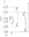
- FIG. 3 In FIG. 3 is shown, in connection with FIG. 2, the evolution over time t of the difference in real time references RTD for each of three pairs (1, 2), (2, 3) and (4, 5) of base stations between which cell changes take place.
- a first analysis of the results shown schematically in this FIG. 3 leads to establishing that one of the two base stations 1 and 2 comprises an oscillator which has a frequency drift relative to the oscillator in the other of said stations.
- This analysis consists, for each pair of base stations, in determining the variation per unit time of the difference in real time references between the two stations. This variation per unit of time is written [(R12 1 - R12 0 ) / (t4-t0)] for the pair of stations (1, 2) for the instants t0 and t4.
- an oscillator of one of the stations of the pair of stations (1, 2) exhibits a frequency drift. It is impossible at this stage to know which of the two stations 1 or 2 has frequency drift. However, a more in-depth analysis leads us to note that only station 1 has a frequency drift relative to the other stations. In fact, only the base stations 1 and 4 in the pair of stations (1, 4) also exhibit a frequency drift between them. On the other hand, the stations 2 and 3 in the pair (2, 3) exhibiting no frequency drift between them. Station 1 belongs to the two couples (1, 2) and (1, 4).
- two variants can be provided according to the invention to establish the drift frequency of an oscillator in a base station.
- the detection of a oscillator with frequency drift is obtained separately for each couple of first and second base stations (i, j) between which operate cell changes.
- this variant includes a first step of calculating the difference between a first time reference of a first oscillator in the first base station and a second time reference a second oscillator in the second base station.
- OTD information is transmitted by two M mobiles a priori separate during two successive handovers between stations i and j at said two instants.
- This calculation step is followed by a step of determining the variation per unit of time of this difference in references temporal.
- a variation per unit of time of the difference in time references which is greater than one predetermined threshold makes it possible to detect that one of said two respective oscillators of said first and second base stations exhibits too much frequency drift high, indeterminacy residing in the selection of one of the two oscillators which presents the drift frequency.
- the second variant of the invention raises this indeterminacy. It provides for this, in addition to the aforementioned steps, a step of selecting one from among two oscillators of the pair of base stations (i, j) which presents the frequency drift, depending on the variation per unit of time of the reference difference temporal which is determined for at least a couple of base stations separate from the couple concerned and comprising one of said first and second base stations.
- This selection step aims to lift the indeterminacy namely which of the two stations of the pair (i, j) includes a oscillator which requires adjustment.
- station i is selected as comprising an oscillator for which a adjustment intervention.
- stations i 'and j in a couple (i ', j) show no drift frequency between them or less drift, the station i is selected as including an oscillator requiring an adjustment intervention since station j does not present a priori no frequency drift.
- the station i is selected as including an oscillator requiring an adjustment intervention.
- infrastructure In the mobile network, or infrastructure, it can be provided infrastructure equipment for implementation of the process of the invention.
- This infrastructure equipment then includes means for receiving from a couple of stations operating in target base stations, messages each including a calculated RTD difference value of time references between source base stations and target, and the pair (i, j) of source base stations and target associated with this calculated RTD value.
- the equipment also includes a memory for storing for each pair of cells, or base stations, between which occur handovers, a set of calculated values of time reference differences between stations. Means are also provided for processing to determine the variation per unit of time the difference in time references for each couple of base stations, and detect drift frequency of an oscillator in response to a variation greater than a predetermined threshold.
- these means select one of the two oscillators which presents the frequency drift as a function of the variation per unit of time of the reference difference time determined for at least two pairs of base station cells each comprising one respective base stations of said each pair.
- radio transmitters including oscillators can replace the base stations, and the mobile can be any transmission relay.
Landscapes
- Engineering & Computer Science (AREA)
- Computer Networks & Wireless Communication (AREA)
- Signal Processing (AREA)
- Mobile Radio Communication Systems (AREA)
- Radio Relay Systems (AREA)
- Monitoring And Testing Of Transmission In General (AREA)
- Measuring Frequencies, Analyzing Spectra (AREA)
Description
- calcul de la différence entre une première référence temporelle du premier oscillateur et une seconde référence temporelle du second oscillateur, pour chacun d'au moins deux instants successifs, en fonction, d'une part, d'une différence observée par un relais entre les première et seconde références temporelles respectivement émises par les premier et second émetteurs, et, d'autre part, des temps de propagation respectifs entre ledit relais et les premier et second émetteur, lesdits premier et second émetteurs formant ensemble un premier couple d'émetteurs,
- détermination de la variation par unité de temps de la différence de références temporelles calculée, et
- détection de la dérive fréquentielle entre lesdits premier et second oscillateurs, en réponse à une variation par unité de temps de la différence de références temporelles calculée qui est supérieure à un seuil prédéterminé.
- la figure 1 illustre de manière schématique un changement de cellule d'un mobile dans un réseau cellulaire de radiocommunications avec des mobiles, et des échanges de messages entre mobile et stations de base source et cible impliquées dans ce changement de cellule; et
- les figures 2 et 3 montrent respectivement un diagramme temporel d'instants de changement de cellule, et un diagramme cartésien associé représentant l'évolution au cours du temps de trois différences de références temporelles respectivement associées à trois couples de stations de base, afin d'expliquer la mise en oeuvre du procédé selon l'invention.
Claims (7)
- Procédé de détection de la dérive fréquentielle entre des premier et second oscillateurs respectivement associés à des premier et second émetteurs radioélectriques, caractérisé en ce qu'il comprend les étapes de :calcul de la différence (RTD = R120, R121) entre une première référence temporelle du premier oscillateur et une seconde référence temporelle du second oscillateur, pour chacun d'au moins deux instants successifs (t0, t4), en fonction, d'une part, d'une différence (OTD) observée par un relais entre les première et seconde références temporelles respectivement émises par les premier et second émetteurs, et, d'autre part, des temps de propagation respectifs entre ledit relais (M) et les premier et second émetteur, lesdits premier et second émetteurs formant ensemble un premier couple d'émetteurs,détermination de la variation par unité de temps (R121-R120/(t4-t0)) de la différence de références temporelles calculée (R120, R121), etdétection de la dérive fréquentielle entre lesdits premier et second oscillateurs, en réponse à une variation par unité de temps de la différence de références temporelles calculée qui est supérieure à un seuil prédéterminé.
- Procédé conforme à la revendication 1, caractérisé par la sélection de l'un parmi les deux oscillateurs qui présente la dérive fréquentielle en fonction de la variation par unité de temps de la différence de références temporelles déterminée pour au moins un autre couple de stations de base distincts dudit premier couple et comprenant l'un desdits premier et second émetteurs.
- Procédé conforme à l'une quelconque des revendications 1 ou 2, caractérisé en ce que lesdits premier et second émetteurs radioélectriques sont respectivement des première et seconde stations de base dans un réseau cellulaire de radiocommunications avec des mobiles, et le relais est un mobile (M) dans ledit réseau.
- Procédé conforme à la revendication 3, caractérisé par la transmission par ledit mobile (M) à destination de la seconde station de base lors d'un changement de cellule, d'une information ayant pour valeur le résultat de l'addition, d'une part, de la différence de références temporelles entre première et seconde stations de base telle qu'observée par le mobile (OTD), et, d'autre part, du temps de propagation (T0) entre le mobile (M) et la première station de base.
- Procédé conforme à la revendication 4, caractérisé en ce que ladite étape de calcul de la différence de références temporelles consiste à soustraire le temps de propagation (T1) entre le mobile et la seconde station de base (BS1) à ladite information (OTD + T0) transmise par le mobile (M) à destination de la seconde station de base (BS1).
- Equipement d'infrastructure pour la mise en oeuvre du procédé conforme à la revendication 1, caractérisé en ce qu'il comprenddes moyens pour recevoir en provenance d'un couple de stations de base, des messages incluant chacun une valeur de différence de références temporelles calculée (RTD),des moyens pour mémoriser pour ce couple de stations lesdites valeurs de différence de références temporelles calculées à des instants successifs, etdes moyens de traitement pour déterminer la variation par unité de temps de la différence de références temporelles, et détecter la dérive fréquentielle d'un oscillateur en réponse à une variation supérieure à un seuil prédéterminé.
- Equipement d'infrastructure conforme à la revendication 6, pour la mise en oeuvre du procédé conforme à la revendication 2, caractérisé en ce qu'il comprend, en outre, des moyens pour sélectionner l'un parmi les deux oscillateurs qui présente la dérive fréquentielle en fonction de la variation par unité de temps de la différence de références temporelles qui est déterminée pour au moins un autre couple de stations de base distincts dudit premier couple et comprenant l'un desdits premier et second émetteurs.
Applications Claiming Priority (2)
| Application Number | Priority Date | Filing Date | Title |
|---|---|---|---|
| FR9410616A FR2724281B1 (fr) | 1994-09-05 | 1994-09-05 | Procede de detection de la derive frequentielle d'un oscillateur de station de base dans un reseau cellulaire de radiocommunications avec des mobiles, et equipement d'infrastructure pour la mise en oeuvre du procede |
| FR9410616 | 1994-09-05 |
Publications (2)
| Publication Number | Publication Date |
|---|---|
| EP0700228A1 EP0700228A1 (fr) | 1996-03-06 |
| EP0700228B1 true EP0700228B1 (fr) | 2001-12-19 |
Family
ID=9466698
Family Applications (1)
| Application Number | Title | Priority Date | Filing Date |
|---|---|---|---|
| EP95401994A Expired - Lifetime EP0700228B1 (fr) | 1994-09-05 | 1995-09-01 | Procédé et équipement pour la détection de la dérive fréquentielle d'un oscillateur de station de base d'un réseau cellulaire de radiocommunications |
Country Status (7)
| Country | Link |
|---|---|
| EP (1) | EP0700228B1 (fr) |
| AT (1) | ATE211342T1 (fr) |
| AU (1) | AU700042B2 (fr) |
| DE (1) | DE69524692T2 (fr) |
| FI (1) | FI954106L (fr) |
| FR (1) | FR2724281B1 (fr) |
| NZ (1) | NZ272807A (fr) |
Family Cites Families (2)
| Publication number | Priority date | Publication date | Assignee | Title |
|---|---|---|---|---|
| FR2646302B1 (fr) * | 1989-04-25 | 1993-01-15 | Matra Communication | Procede de pseudo-synchronisation d'un reseau de communication a multiplexage dans le temps et applications |
| FR2695776B1 (fr) * | 1992-09-15 | 1994-10-14 | Alcatel Radiotelephone | Procédé de transmission d'une information d'avance temporelle à un mobile évoluant dans des cellules d'un réseau GSM à BTS asynchrones. |
-
1994
- 1994-09-05 FR FR9410616A patent/FR2724281B1/fr not_active Expired - Fee Related
-
1995
- 1995-08-18 NZ NZ272807A patent/NZ272807A/en unknown
- 1995-08-21 AU AU30134/95A patent/AU700042B2/en not_active Ceased
- 1995-09-01 AT AT95401994T patent/ATE211342T1/de not_active IP Right Cessation
- 1995-09-01 DE DE69524692T patent/DE69524692T2/de not_active Expired - Fee Related
- 1995-09-01 EP EP95401994A patent/EP0700228B1/fr not_active Expired - Lifetime
- 1995-09-01 FI FI954106A patent/FI954106L/fi unknown
Also Published As
| Publication number | Publication date |
|---|---|
| EP0700228A1 (fr) | 1996-03-06 |
| FI954106A0 (fi) | 1995-09-01 |
| FR2724281B1 (fr) | 1996-12-20 |
| AU3013495A (en) | 1996-03-21 |
| ATE211342T1 (de) | 2002-01-15 |
| FI954106A7 (fi) | 1996-03-06 |
| FR2724281A1 (fr) | 1996-03-08 |
| FI954106L (fi) | 1996-03-06 |
| DE69524692T2 (de) | 2002-09-12 |
| DE69524692D1 (de) | 2002-01-31 |
| AU700042B2 (en) | 1998-12-17 |
| NZ272807A (en) | 1997-02-24 |
Similar Documents
| Publication | Publication Date | Title |
|---|---|---|
| EP0593320B1 (fr) | Procédé de transmission d'une information d'avance temporelle à un mobile évoluant dans un réseau de radiotéléphonie cellulaire, mobile, contrÔleur et système d'échange d'informations mettant en oeuvre un tel procédé | |
| EP0698318B1 (fr) | Procede de transfert intercellulaire, ou handover, entre deux cellules d'un reseau cellulaire de radiocommunications mobiles | |
| EP0589753B2 (fr) | Procédé de transmission d'une information d'avance temporelle à un mobile dans un réseau cellulaire avec la commande de transfert de stations de base | |
| EP0398773B1 (fr) | Procédé de pseudo-synchronisation d'un réseau de communication à multiplexage dans le temps et applications. | |
| EP1271977B1 (fr) | Procédé de basculement d'un premier mode de radiocommunication vers un second mode de radiocommunication et terminal mobile multi-mode associé | |
| CA2034411C (fr) | Procede de transfert de communication dans un reseau de radiotelephonie | |
| EP0893931A1 (fr) | Procédé de détermination d'une information d'avance temporelle dans uns systéme de radiocommunication cellulaire | |
| EP0936758A2 (fr) | Methode de determination de differences de temps dans un systeme de telecommunication cellulaire | |
| JP2000504838A (ja) | 移動無線端末の位置を決定する方法および装置 | |
| EP0918404A1 (fr) | Station de base pour système cellulaire de radiocommunications mobiles et système de synchronisation de telles stations de base | |
| FR2739243A1 (fr) | Systeme cellulaire de radiocommunications mobiles, station de base et dispositif de controle de stations de base correspondants | |
| EP0903049B1 (fr) | Procede de gestion des transferts intercellulaires des radiocommunications dans un systeme de radiocommunication cellulaire | |
| FR2782226A1 (fr) | Procede de localisation d'un telephone mobile | |
| US6324406B1 (en) | Mobile station location determination using radio signal timing values | |
| EP2262314A2 (fr) | Procédé de configuration de mode compressé dans un système de radiocommunications mobiles | |
| EP1315392A1 (fr) | Procédé pour le changement de cellule dans un système cellulaire de radiocommunications mobiles en mode paquet | |
| EP0721291A1 (fr) | Procédé et système pour réduire la durée d'une phase de rattachement d'un mobile à une station de base d'un réseau cellulaire de radiocommunications | |
| EP0700228A1 (fr) | Procédé et équipement pour la détection de la dérive fréquentielle d'un socillateur de station de base d'un réseau cellulaire de radiocommunications | |
| FR2652468A1 (fr) | Procede de synchronisation dans un systeme de radio mobile. | |
| WO1999013671A1 (fr) | Procede de transfert de communication entre deux cellules d'un reseau de radio-communication cellulaire numerique | |
| EP2190131B1 (fr) | Procédé de gestion d'antennes pour un système de communication par onde radiofréquence de type dect et système correspondant | |
| EP1097599A1 (fr) | Systeme de localisation de telephones mobiles | |
| EP1879419B1 (fr) | Détection de collision asynchrone dans un système de téléphonie mobile directe | |
| FR2724076A1 (fr) | Procede de conservation de la synchronisation temporelle d'une station mobile dans un systeme de radiocommunication numerique cellulaire | |
| Zhao et al. | Positioning assisted inter-segment handover for integrated GSM-satellite mobile system |
Legal Events
| Date | Code | Title | Description |
|---|---|---|---|
| PUAI | Public reference made under article 153(3) epc to a published international application that has entered the european phase |
Free format text: ORIGINAL CODE: 0009012 |
|
| AK | Designated contracting states |
Kind code of ref document: A1 Designated state(s): AT BE CH DE DK ES GB IT LI NL SE |
|
| 17P | Request for examination filed |
Effective date: 19960712 |
|
| GRAG | Despatch of communication of intention to grant |
Free format text: ORIGINAL CODE: EPIDOS AGRA |
|
| 17Q | First examination report despatched |
Effective date: 20010321 |
|
| GRAG | Despatch of communication of intention to grant |
Free format text: ORIGINAL CODE: EPIDOS AGRA |
|
| GRAH | Despatch of communication of intention to grant a patent |
Free format text: ORIGINAL CODE: EPIDOS IGRA |
|
| GRAH | Despatch of communication of intention to grant a patent |
Free format text: ORIGINAL CODE: EPIDOS IGRA |
|
| GRAA | (expected) grant |
Free format text: ORIGINAL CODE: 0009210 |
|
| RAP1 | Party data changed (applicant data changed or rights of an application transferred) |
Owner name: ALCATEL |
|
| AK | Designated contracting states |
Kind code of ref document: B1 Designated state(s): AT BE CH DE DK ES GB IT LI NL SE |
|
| PG25 | Lapsed in a contracting state [announced via postgrant information from national office to epo] |
Ref country code: NL Free format text: LAPSE BECAUSE OF FAILURE TO SUBMIT A TRANSLATION OF THE DESCRIPTION OR TO PAY THE FEE WITHIN THE PRESCRIBED TIME-LIMIT Effective date: 20011219 Ref country code: IT Free format text: LAPSE BECAUSE OF FAILURE TO SUBMIT A TRANSLATION OF THE DESCRIPTION OR TO PAY THE FEE WITHIN THE PRE;WARNING: LAPSES OF ITALIAN PATENTS WITH EFFECTIVE DATE BEFORE 2007 MAY HAVE OCCURRED AT ANY TIME BEFORE 2007. THE CORRECT EFFECTIVE DATE MAY BE DIFFERENT FROM THE ONE RECORDED.SCRIBED TIME-LIMIT Effective date: 20011219 Ref country code: AT Free format text: LAPSE BECAUSE OF FAILURE TO SUBMIT A TRANSLATION OF THE DESCRIPTION OR TO PAY THE FEE WITHIN THE PRESCRIBED TIME-LIMIT Effective date: 20011219 |
|
| REF | Corresponds to: |
Ref document number: 211342 Country of ref document: AT Date of ref document: 20020115 Kind code of ref document: T |
|
| REG | Reference to a national code |
Ref country code: CH Ref legal event code: EP |
|
| REG | Reference to a national code |
Ref country code: GB Ref legal event code: IF02 |
|
| GBT | Gb: translation of ep patent filed (gb section 77(6)(a)/1977) |
Effective date: 20020102 |
|
| REF | Corresponds to: |
Ref document number: 69524692 Country of ref document: DE Date of ref document: 20020131 |
|
| PG25 | Lapsed in a contracting state [announced via postgrant information from national office to epo] |
Ref country code: SE Free format text: LAPSE BECAUSE OF FAILURE TO SUBMIT A TRANSLATION OF THE DESCRIPTION OR TO PAY THE FEE WITHIN THE PRESCRIBED TIME-LIMIT Effective date: 20020319 Ref country code: DK Free format text: LAPSE BECAUSE OF FAILURE TO SUBMIT A TRANSLATION OF THE DESCRIPTION OR TO PAY THE FEE WITHIN THE PRESCRIBED TIME-LIMIT Effective date: 20020319 |
|
| NLV1 | Nl: lapsed or annulled due to failure to fulfill the requirements of art. 29p and 29m of the patents act | ||
| PG25 | Lapsed in a contracting state [announced via postgrant information from national office to epo] |
Ref country code: ES Free format text: LAPSE BECAUSE OF FAILURE TO SUBMIT A TRANSLATION OF THE DESCRIPTION OR TO PAY THE FEE WITHIN THE PRESCRIBED TIME-LIMIT Effective date: 20020627 |
|
| PG25 | Lapsed in a contracting state [announced via postgrant information from national office to epo] |
Ref country code: LI Free format text: LAPSE BECAUSE OF NON-PAYMENT OF DUE FEES Effective date: 20020930 Ref country code: CH Free format text: LAPSE BECAUSE OF NON-PAYMENT OF DUE FEES Effective date: 20020930 Ref country code: BE Free format text: LAPSE BECAUSE OF NON-PAYMENT OF DUE FEES Effective date: 20020930 |
|
| PLBE | No opposition filed within time limit |
Free format text: ORIGINAL CODE: 0009261 |
|
| STAA | Information on the status of an ep patent application or granted ep patent |
Free format text: STATUS: NO OPPOSITION FILED WITHIN TIME LIMIT |
|
| 26N | No opposition filed | ||
| BERE | Be: lapsed |
Owner name: *ALCATEL Effective date: 20020930 |
|
| REG | Reference to a national code |
Ref country code: CH Ref legal event code: PL |
|
| NLV1 | Nl: lapsed or annulled due to failure to fulfill the requirements of art. 29p and 29m of the patents act | ||
| PGFP | Annual fee paid to national office [announced via postgrant information from national office to epo] |
Ref country code: GB Payment date: 20080918 Year of fee payment: 14 |
|
| PGFP | Annual fee paid to national office [announced via postgrant information from national office to epo] |
Ref country code: DE Payment date: 20080919 Year of fee payment: 14 |
|
| GBPC | Gb: european patent ceased through non-payment of renewal fee |
Effective date: 20090901 |
|
| PG25 | Lapsed in a contracting state [announced via postgrant information from national office to epo] |
Ref country code: DE Free format text: LAPSE BECAUSE OF NON-PAYMENT OF DUE FEES Effective date: 20100401 |
|
| PG25 | Lapsed in a contracting state [announced via postgrant information from national office to epo] |
Ref country code: GB Free format text: LAPSE BECAUSE OF NON-PAYMENT OF DUE FEES Effective date: 20090901 |