EP0700363B1 - Patrone, vorrichtungen und verfahren zur abgabe von flüssigkeiten - Google Patents
Patrone, vorrichtungen und verfahren zur abgabe von flüssigkeiten Download PDFInfo
- Publication number
- EP0700363B1 EP0700363B1 EP94910866A EP94910866A EP0700363B1 EP 0700363 B1 EP0700363 B1 EP 0700363B1 EP 94910866 A EP94910866 A EP 94910866A EP 94910866 A EP94910866 A EP 94910866A EP 0700363 B1 EP0700363 B1 EP 0700363B1
- Authority
- EP
- European Patent Office
- Prior art keywords
- cartridge
- liquid
- section
- piercer
- pierceable
- Prior art date
- Legal status (The legal status is an assumption and is not a legal conclusion. Google has not performed a legal analysis and makes no representation as to the accuracy of the status listed.)
- Expired - Lifetime
Links
- 239000007788 liquid Substances 0.000 title claims description 107
- 238000000034 method Methods 0.000 title description 5
- 239000007921 spray Substances 0.000 claims description 63
- 239000007787 solid Substances 0.000 claims description 7
- 230000000694 effects Effects 0.000 claims description 3
- 210000001508 eye Anatomy 0.000 description 19
- 210000003128 head Anatomy 0.000 description 15
- 239000000463 material Substances 0.000 description 14
- 238000007789 sealing Methods 0.000 description 12
- 229920003023 plastic Polymers 0.000 description 9
- 239000004033 plastic Substances 0.000 description 9
- 230000036512 infertility Effects 0.000 description 8
- -1 polypropylene Polymers 0.000 description 6
- 239000004743 Polypropylene Substances 0.000 description 5
- 229910052782 aluminium Inorganic materials 0.000 description 5
- 230000008901 benefit Effects 0.000 description 5
- 239000003814 drug Substances 0.000 description 5
- 239000007789 gas Substances 0.000 description 5
- 229920000728 polyester Polymers 0.000 description 5
- 229920001155 polypropylene Polymers 0.000 description 5
- XAGFODPZIPBFFR-UHFFFAOYSA-N aluminium Chemical compound [Al] XAGFODPZIPBFFR-UHFFFAOYSA-N 0.000 description 4
- 239000006196 drop Substances 0.000 description 4
- 229940079593 drug Drugs 0.000 description 4
- 210000004279 orbit Anatomy 0.000 description 4
- 238000011109 contamination Methods 0.000 description 3
- 239000002985 plastic film Substances 0.000 description 3
- 230000000712 assembly Effects 0.000 description 2
- 238000000429 assembly Methods 0.000 description 2
- 210000005252 bulbus oculi Anatomy 0.000 description 2
- 230000007812 deficiency Effects 0.000 description 2
- 230000000994 depressogenic effect Effects 0.000 description 2
- 230000001815 facial effect Effects 0.000 description 2
- 229920002457 flexible plastic Polymers 0.000 description 2
- 229920001903 high density polyethylene Polymers 0.000 description 2
- 239000004700 high-density polyethylene Substances 0.000 description 2
- YAFQFNOUYXZVPZ-UHFFFAOYSA-N liproxstatin-1 Chemical compound ClC1=CC=CC(CNC=2C3(CCNCC3)NC3=CC=CC=C3N=2)=C1 YAFQFNOUYXZVPZ-UHFFFAOYSA-N 0.000 description 2
- 229920001684 low density polyethylene Polymers 0.000 description 2
- 239000004702 low-density polyethylene Substances 0.000 description 2
- 238000004519 manufacturing process Methods 0.000 description 2
- 229910052751 metal Inorganic materials 0.000 description 2
- 239000002184 metal Substances 0.000 description 2
- 229920006255 plastic film Polymers 0.000 description 2
- 229920000915 polyvinyl chloride Polymers 0.000 description 2
- 239000004800 polyvinyl chloride Substances 0.000 description 2
- 239000004677 Nylon Substances 0.000 description 1
- 239000004698 Polyethylene Substances 0.000 description 1
- NIXOWILDQLNWCW-UHFFFAOYSA-N acrylic acid group Chemical group C(C=C)(=O)O NIXOWILDQLNWCW-UHFFFAOYSA-N 0.000 description 1
- 206010003246 arthritis Diseases 0.000 description 1
- 230000015572 biosynthetic process Effects 0.000 description 1
- 238000007796 conventional method Methods 0.000 description 1
- 238000012864 cross contamination Methods 0.000 description 1
- 230000006837 decompression Effects 0.000 description 1
- 230000002950 deficient Effects 0.000 description 1
- 230000006866 deterioration Effects 0.000 description 1
- 238000006073 displacement reaction Methods 0.000 description 1
- 230000009977 dual effect Effects 0.000 description 1
- 238000001125 extrusion Methods 0.000 description 1
- 239000003889 eye drop Substances 0.000 description 1
- 229940012356 eye drops Drugs 0.000 description 1
- 210000005224 forefinger Anatomy 0.000 description 1
- 230000005484 gravity Effects 0.000 description 1
- 239000011261 inert gas Substances 0.000 description 1
- 239000002650 laminated plastic Substances 0.000 description 1
- 238000012423 maintenance Methods 0.000 description 1
- 238000002483 medication Methods 0.000 description 1
- 238000012986 modification Methods 0.000 description 1
- 230000004048 modification Effects 0.000 description 1
- 229920001778 nylon Polymers 0.000 description 1
- 230000035699 permeability Effects 0.000 description 1
- 229920000515 polycarbonate Polymers 0.000 description 1
- 239000004417 polycarbonate Substances 0.000 description 1
- 229920000573 polyethylene Polymers 0.000 description 1
- 239000003755 preservative agent Substances 0.000 description 1
- 230000002335 preservative effect Effects 0.000 description 1
- 239000003566 sealing material Substances 0.000 description 1
- 239000002356 single layer Substances 0.000 description 1
- 230000001954 sterilising effect Effects 0.000 description 1
- 238000004659 sterilization and disinfection Methods 0.000 description 1
- 210000003813 thumb Anatomy 0.000 description 1
- 239000002699 waste material Substances 0.000 description 1
- XLYOFNOQVPJJNP-UHFFFAOYSA-N water Substances O XLYOFNOQVPJJNP-UHFFFAOYSA-N 0.000 description 1
Images




Classifications
-
- B—PERFORMING OPERATIONS; TRANSPORTING
- B05—SPRAYING OR ATOMISING IN GENERAL; APPLYING FLUENT MATERIALS TO SURFACES, IN GENERAL
- B05B—SPRAYING APPARATUS; ATOMISING APPARATUS; NOZZLES
- B05B11/00—Single-unit hand-held apparatus in which flow of contents is produced by the muscular force of the operator at the moment of use
- B05B11/01—Single-unit hand-held apparatus in which flow of contents is produced by the muscular force of the operator at the moment of use characterised by the means producing the flow
- B05B11/06—Gas or vapour producing the flow, e.g. from a compressible bulb or air pump
-
- A—HUMAN NECESSITIES
- A61—MEDICAL OR VETERINARY SCIENCE; HYGIENE
- A61F—FILTERS IMPLANTABLE INTO BLOOD VESSELS; PROSTHESES; DEVICES PROVIDING PATENCY TO, OR PREVENTING COLLAPSING OF, TUBULAR STRUCTURES OF THE BODY, e.g. STENTS; ORTHOPAEDIC, NURSING OR CONTRACEPTIVE DEVICES; FOMENTATION; TREATMENT OR PROTECTION OF EYES OR EARS; BANDAGES, DRESSINGS OR ABSORBENT PADS; FIRST-AID KITS
- A61F9/00—Methods or devices for treatment of the eyes; Devices for putting in contact-lenses; Devices to correct squinting; Apparatus to guide the blind; Protective devices for the eyes, carried on the body or in the hand
- A61F9/0008—Introducing ophthalmic products into the ocular cavity or retaining products therein
-
- A—HUMAN NECESSITIES
- A61—MEDICAL OR VETERINARY SCIENCE; HYGIENE
- A61M—DEVICES FOR INTRODUCING MEDIA INTO, OR ONTO, THE BODY; DEVICES FOR TRANSDUCING BODY MEDIA OR FOR TAKING MEDIA FROM THE BODY; DEVICES FOR PRODUCING OR ENDING SLEEP OR STUPOR
- A61M15/00—Inhalators
- A61M15/0028—Inhalators using prepacked dosages, one for each application, e.g. capsules to be perforated or broken-up
-
- A—HUMAN NECESSITIES
- A61—MEDICAL OR VETERINARY SCIENCE; HYGIENE
- A61M—DEVICES FOR INTRODUCING MEDIA INTO, OR ONTO, THE BODY; DEVICES FOR TRANSDUCING BODY MEDIA OR FOR TAKING MEDIA FROM THE BODY; DEVICES FOR PRODUCING OR ENDING SLEEP OR STUPOR
- A61M15/00—Inhalators
- A61M15/0028—Inhalators using prepacked dosages, one for each application, e.g. capsules to be perforated or broken-up
- A61M15/003—Inhalators using prepacked dosages, one for each application, e.g. capsules to be perforated or broken-up using capsules, e.g. to be perforated or broken-up
- A61M15/0033—Details of the piercing or cutting means
-
- B—PERFORMING OPERATIONS; TRANSPORTING
- B05—SPRAYING OR ATOMISING IN GENERAL; APPLYING FLUENT MATERIALS TO SURFACES, IN GENERAL
- B05B—SPRAYING APPARATUS; ATOMISING APPARATUS; NOZZLES
- B05B11/00—Single-unit hand-held apparatus in which flow of contents is produced by the muscular force of the operator at the moment of use
- B05B11/01—Single-unit hand-held apparatus in which flow of contents is produced by the muscular force of the operator at the moment of use characterised by the means producing the flow
- B05B11/02—Membranes or pistons acting on the contents inside the container, e.g. follower pistons
-
- A—HUMAN NECESSITIES
- A61—MEDICAL OR VETERINARY SCIENCE; HYGIENE
- A61M—DEVICES FOR INTRODUCING MEDIA INTO, OR ONTO, THE BODY; DEVICES FOR TRANSDUCING BODY MEDIA OR FOR TAKING MEDIA FROM THE BODY; DEVICES FOR PRODUCING OR ENDING SLEEP OR STUPOR
- A61M2202/00—Special media to be introduced, removed or treated
- A61M2202/04—Liquids
-
- A—HUMAN NECESSITIES
- A61—MEDICAL OR VETERINARY SCIENCE; HYGIENE
- A61M—DEVICES FOR INTRODUCING MEDIA INTO, OR ONTO, THE BODY; DEVICES FOR TRANSDUCING BODY MEDIA OR FOR TAKING MEDIA FROM THE BODY; DEVICES FOR PRODUCING OR ENDING SLEEP OR STUPOR
- A61M2210/00—Anatomical parts of the body
- A61M2210/06—Head
- A61M2210/0612—Eyes
-
- A—HUMAN NECESSITIES
- A61—MEDICAL OR VETERINARY SCIENCE; HYGIENE
- A61M—DEVICES FOR INTRODUCING MEDIA INTO, OR ONTO, THE BODY; DEVICES FOR TRANSDUCING BODY MEDIA OR FOR TAKING MEDIA FROM THE BODY; DEVICES FOR PRODUCING OR ENDING SLEEP OR STUPOR
- A61M2210/00—Anatomical parts of the body
- A61M2210/06—Head
- A61M2210/0618—Nose
Definitions
- This invention relates to cartridges for providing a liquid to be dispensed and to devices for dispensing a liquid from such cartridges, such as a liquid containing medicaments and drugs.
- a liquid containing medicaments and drugs Preferably, such liquids are dispensed to the eye of a user.
- a variety of devices for dispensing liquid are known. Exemplary devices for dispensing a liquid to the eye of a user are disclosed in, e.g., U.S. Patent Nos. 3,087,656; 3,788,528; 4,623,337; 4,811,866; and 4,925,065. Included among these devices are both multi-dose and single-dose devices.
- Multi-dose devices pose problems with product sterility, e.g., when the device is used repeatedly to dispense liquid to the eye. Although practically all such devices and their contents are sterile before they are opened for use, not only is the product within the dispenser no longer sterile after opening but there is danger of contamination of the contents by the user, as well as cross-contamination where several people, e.g., family members, use the same dispensing device.
- Maintaining sterility of the product to be dispensed is not only necessary to prevent contamination but is also a desirable feature to reduce or eliminate the need for a preservative.
- volume of liquid dispensed by dispensing devices on the market today typically droplets of liquid in excess of 35 ⁇ l and some as high as 56 ⁇ l, results in waste. Since the eye can only hold 25 ⁇ l, see, e.g., Keister et al., Journal of Pharmaceutical Sciences , 80 (1991) 50-53, anything in excess of 35 ⁇ l will be wasted. Even in cases where cost is not a factor, droplet size can be important, e.g., in cases where the efficiency of a medication is greatly enhanced with a droplet size of about 10 ⁇ l (see, e.g., Keister et al., supra).
- US-A-2 888 924 discloses hypodermic syringes within a duplex arrangement comprising a tubular applicator having two tubular apertures at opposite ends thereof into which respectively adapted compressible syringes made of thin aluminum sheet are inserted.
- the syringes contain in their cylinder a liquid to be injected and a hollow needle connected to a solid plate welded to the outer aluminum shell of the syringe.
- the syringe cylinder further comprises a pierceable section, opposite to the solid plate supporting the needle, which section is pierced by the needle upon compressing the aluminum cylinder by actuating means of the applicator. Prior to piercing the pierceable section, said needle is disposed in the liquid.
- the present invention provides cartridges for providing a liquid to be dispensed, as well as devices for dispensing liquids from such cartridges. Although in a preferred embodiment of the present invention the liquid is dispensed to the eye of a user, the present invention can be used to deliver liquid to, e.g., the nose or ear of a user.
- Cartridges of the present invention for providing a liquid comprise a container having, the liquid to be dispensed disposed therein, wherein the container comprises a pierceable section and a solid piercer capable of piercing the pierceable section, with said piercer being disposed in the liquid prior to piercing the pierceable section.
- the piercer is internal to the container for the liquid thereby making it possible to maintain the sterility of the liquid until the moment of use.
- the pierceable section of such containers is provided by conventional materials, such as pierceable plastics, plastic laminates, and plastic metal laminates.
- Piercers for use in the present invention may be manufactured independently of the container or as an integral part of the container.
- the piercer is moved towards and pierces the pierceable section of the container.
- the pierceable section is moved towards and is pierced by the piercer.
- the cartridges are provided with a head space of air between the liquid and the pierceable section.
- the air in the head space compresses readily thereby facilitating movement of the piercer and/or the pierceable section.
- the air or gas in the head space also facilitates dispensing of the liquid.
- the piercer is positioned with respect to the pierceable section so as to limit the degree of movement necessary to achieve piercing of the seal.
- the piercer is provided with a sealing lip to provide an interference or sealing fit with the inner wall of the container to minimize or prevent the liquid from flowing between the piercer and the inner wall of the container.
- the sealing lip allows the piercer to be constructed with clearance between the piercer and container to reduce friction, while the sealing lip, which is preferably short and very flexible, provides a seal against leakage past the piercer.
- the piercer may be hollow and open at the end distal to the pierceable section.
- the piercer When a sealing lip is not provided, i.e., the fit with the inner wall of the container is not an interference fit, the piercer is closed at the end distal to the pierceable section to minimize the volume of liquid which can flow away from the pierceable section.
- the piercer is dimensioned so as to fit within the container, and where a sealing lip is present, so that the sealing lip provides an interference fit with the inner wall of the container.
- the volume of liquid dispensed from the cartridge is determined by the size of the container, piercer and head space. By appropriately dimensioning these components, the desired volume can be readily achieved. In all embodiments, any residual liquid is taken into account in formulating the appropriate volume to provide the desired dosage.
- the cartridges of the present invention are intended for use with any device capable of dispensing the liquid therefrom.
- the cartridges of the present invention may be used with various dispensing devices that properly orient the cartridge with respect to the eye, nose or ear of a user and that also provide for appropriate movement to enable the piercer to pierce the pierceable section. As mentioned above, movement of the piercer towards the pierceable section and vice versa is included within the scope of the present invention.
- a spray head is provided for use in conjunction with the cartridges of the present invention.
- the spray head fits over the cartridge at the pierceable section thereof and is provided with an orifice through which the liquid to be dispensed is directed when the piercer pierces the pierceable section of the cartridge.
- the spray head together with the cartridge is sometimes hereinafter referred to as the cartridge assembly.
- the present invention also provides dispensing devices for receiving a cartridge assembly and dispensing the liquid therefrom.
- the dispensing device is provided with a receptacle for receiving the cartridge assembly at the spray head.
- the receptacle is provided with an opening aligned with the opening in the spray head for dispensing the liquid.
- Preferred dispensers are also provided with a member for positioning the device at the eye of the user so that the liquid will strike the eyeball of the user as it is dispensed.
- the spray head is incorporated into the body of the dispenser.
- the cartridges and devices of the present invention overcome many of the disadvantages associated with known devices and methods of dispensing liquid to the eye of a user.
- One important advantage resides in the fact that the cartridge cannot be used again, thereby obviating the reuse problem, and resultant loss of sterility associated with many units on the market which are intended as single-dose units.
- Another important advantage is total protection of the liquid until the moment of use. Loss of sterility is avoided, because the liquid to be dispensed is not exposed to the air except during actual usage.
- the devices of the present invention dispense a discrete volume each time, regardless of the manner in which the actuator is depressed. Even when a conventional eye-dropper is manipulated very carefully, the smallest droplet that will free fall from the tip is approximately 35 ⁇ l of water. This is due to the effect of surface tension between the liquid and the tip of the dropper and also the liquid remaining inside the tip.
- the devices of the present invention dispense liquid under pressure, e.g., by piston action of the piercer or by simple displacement of the liquid and, in some embodiments, with an assist from the expanding air or gas in the head space. This in part, enables the successful dispensing of droplets as small as 6 ⁇ l. It is believed that the devices of the present invention can be used for those medications where a droplet size of 10 ⁇ l or less is a necessary requirement.
- the devices of the present invention require little or no coordinatioon on the part of the user. This is an important advantage for users who experience difficulties in applying eye drops due to physical infirmities, such as arthritis and other disabling conditions.
- the devices of the present invention enable the user to more easily and accurately dispense the required dosage to the eye.
- the unit can be operated from any direction, upright, horizontal or even from a downward position. Because the dispenser is positioned directly over the eye socket and the liquid is dispensed from the center axis, the droplet is directed very accurately onto the eyeball.
- the present invention provides benefits in terms of economy as well as sterility and droplet size.
- Dispensers for use with the aforesaid cartridge assemblies can be used repeatedly, thus enabling the user to purchase only the cartridges or the cartridge assemblies containing the liquid to be dispensed.
- the dispenser can be readily molded from inexpensive plastic in high volume thereby further reducing the cost.
- a further saving is effected with the product.
- Fig. 1 is a cross-sectional view of one embodiment of a cartridge in accordance with the present invention for holding a liquid to be dispensed.
- Fig. 2 is a cross-sectional view of one embodiment of a spray head in accordance with the present invention.
- Fig. 3 is an enlarged cross-sectional view of a piercer similar to that shown in Fig. 1.
- Fig. 4 is a cross-sectional view of the container and spray tip shown in Figs. 1 and 2 respectively in one embodiment of a dispenser in accordance with the present invention.
- Fig. 5 is a view of the device shown in Fig. 4, wherein the liquid has been dispensed.
- Fig. 6 shows one embodiment of a holder in accordance with the present invention.
- Fig. 7 shows another preferred embodiment of a container for holding liquid to be dispensed in accordance with the present invention.
- Fig. 8 shows a piercer in accordance with the present invention.
- Fig, 9 show a pierceable seal for use with the container shown in Fig. 7.
- Fig. 10 is another embodiment of a cartridge in accordance with the present invention for holding a liquid to be dispensed.
- Fig. 11 shows a cross-sectional view of yet another embodiment of the device in accordance with present invention.
- Fig. 12 is a cross-sectional view of the device shown in Fig. 11 wherein the liquid has been dispensed.
- Fig. 13 is a rear view of the dispenser shown in Fig. 4.
- Fig. 14 is a front plan view of the piercer shown in Fig. 3.
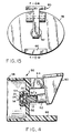
- Fig. 15 is a front view of the piercer shown in Fig. 8.
- Fig. 16 is a rear view of the container shown in Fig. 6.
- Fig. 17 is a cross-sectional view of another preferred cartridge assembly of the present invention.
- Fig. 18 shows the device of Fig. 17 as the piercer is piercing the pierceable section.
- Fig. 19 shows the device of Fig. 18 wherein the piercer has completely pierced the pierceable section and the liquid has been dispensed.
- Fig. 20 shows a dual cartridge assembly in accordance with the present invention.
- liquid dispensing cartridges and devices of the present invention are primarily illustrated by those which have been adapted for delivery of liquids to the eye of a user, it will be appreciated by those skilled in the art that such devices may also be adapted for dispensing liquid to, e.g., the nose or the ear of a user.
- FIG. 1 there is shown one embodiment of a cartridge 10 in accordance with the present invention for containing a liquid to be dispensed.
- Cartridge 10 comprises container 11 for containing a liquid to be dispensed, the container 11 comprising the liquid 2, pierceable section 4, piercer 6 capable of piercing pierceable section 4 when moved into contact therewith, and moveable, e.g., collapsible or foldable, section 12.
- Piercer 6 shown in Fig. 3 is not an integral part of container 11 but rather is manufactured separtely.
- Piercer 6 comprises a cylinder having projecting axially from the front end thereof a smaller cylindrical pointed member 9.
- Fig. 10 shows another preferred embodiment of a cartridge 40 in accordance with the present invention for providing a liquid to be dispensed.
- Figs. 6 through 9 show the components of cartridge 40.
- cartridge 40 comprises flexible container 41 shown in Fig. 7, piercer 6' shown in Fig. 8, pierceable seal 8 shown in Fig. 9 for sealing flexible container 41, once piercer 6' and the liquid 2 to be dispensed are disposed therein, and holder 46 shown in Fig. 6 for receiving flexible container 41.
- Flexible container 41 is provided with flange 42.
- holder 46 is provided with plug 44 positioned in holder 46 by means of webs 47,47' shown in Figs. 12 and 16. Pierceable seal 8 and flange 42 are welded together and also to the rim of holder 46, preferably in one operation.
- FIG. 2 there is shown one embodiment of a spray head 20 for use in conjunction with cartridge 10 of Fig. 1 and cartridge 40 of Fig. 10.
- a spray head having a cartridge disposed therein is hereinafter sometimes referred to as a cartridge assembly.
- Spray head 20 comprises spray tip 21 and socket 23 dimensioned to receive a cartridge at its pierceable section.
- Socket 23 is provided with section 22 for receiving the pointed member 9,9' of piercer 6,6'.
- spray tip 21 is provided with orifice 24 which, when a cartridge is disposed in socket 23, is open to the atmosphere and to the pierceable section of the cartridge.
- Socket 23 is provided with annular projection 26.
- the present invention also provides dispensing devices for receiving a cartridge assembly and for dispensing the liquid therefrom.
- dispenser 50 having disposed therein spray head 20 and cartridge 10.
- cartridge 10 is shown in Fig. 4, cartridge 40 could be substituted therefor.
- Figs. 11 and 12 is shown a partial view of dispenser 50 having cartridge 40 disposed therein.
- dispenser 50 comprises body member 52 which is provided with receptacle 54 for receiving a cartridge assembly.
- Receptacle 54 is adapted to engage spray head 20 and is provided with opening 56 which is aligned with orifice 24 in spray tip 21. As the liquid is dispensed, it passes through orifice 24 and opening 56. Opening 56 is dimensioned larger than orifice 24 in spray tip 21 to minimize impingement on dispenser 50 of the liquid to be dispensed.
- body member 52 also comprises a projecting front member 58 for positioning opening 56 of receptacle 54 and orifice 24 of spray tip 21 in front of the user's eye.
- Projecting number 58 is adapted to conform to the shape of the facial area surrounding the eye socket of a user and, in a preferred embodiment, is similar in shape to the common eye cup.
- Body member 52 further comprises actuating member 60 movably connected thereto by hinge 64.
- Actuating member 60 is provided with projecting member 62 which abuts the end of cartridge 10 or 40 when the cartridge assembly is disposed in receptacle 54, i.e., loaded into dispenser 50.
- Body member 52 also comprises base member 66.
- actuating member 60 is lifted up to clear receptacle 54 for positioning of spray head 20 and cartridge 10 or 40.
- Spray head 20 and cartridge 10 or 40 is placed into receptacle 54, with spray head 20 inward, and projecting member 62 of actuating member 60 is allowed to drop freely against the projecting end of cartridge 10 or 40.
- the device is clasped at the top of actuating member 60 and at base member 66 between the thumb and forefinger and projecting member 58 is placed around the eye socket of the user to position orifice 24 and opening 56 at the eye of the user.
- a quick press by the user on actuator 60 causes the liquid to be dispensed through orifice 24 in spray tip 20 and opening 56 in receptacle 54.
- projecting member 62 of actuating member 60 engages the moveable section of cartridge 10 or 40 and moves it and the piercer towards the pierceable section, thereby causing the piercer to pierce the pierceable section as shown in Figs. 5 and 12.
- the liquid is dispensed by the piston action of piercer 6,6' and, in embodiments wherein the head space is provided between the liquid and the pierceable section, with an assist by expansion of compressed air or gas in the head space.
- actuating member 60 is moveable towards and projection 62 is contactable with moveable plug 44.
- a quick press by the user on actuating member 60 causes projection 62 to engage moveable section 44 and move it forward, breaking webs 47,47', thereby enabling actuating member 60 to move plug 44 towards pierceable seal 8.
- This causes piercer 6' to move forward and pierce pierceable seal 8 as shown in Fig. 12.
- liquid 2 is dispensed through orifice 24 in spray tip 21 and opening 56 in receptacle 54.
- FIG. 13 A rear view of dispenser 50 is shown in Fig. 13.
- the pierceable seal is moveable towards the piercer.
- Piercer 70 is formed as an integral part of container 80.
- the cartridge is disposed in spray head 90 before actuation.
- Spray head 90 is similar in structure to spray head 20, similar structures are given the same identifying numbers.
- annular projection 92 of socket 23 engages pierceable section 4 and causes piercing thereof as shown in Figs. 19 and 20. Liquid is dispensed through orifice 24 in spray tip 21.
- spray heads in accordance with the present invention can be configured to receive, two or more cartridges, where it is desired to dispense two or more liquids simultaneously.
- the volume of the cartridges can be varied to dispense various proportions of liquids.
- Connecting member 86 is provided, to receive the liquids after piercing of the cartridges and to lead the liquids to common terminal orifice 24 in spray tip 21.
- the force exerted by actuating member 60 is transmitted directly to the back of the piercer and hydrostatically to the pierceable section, forming a seal against annular projection 26 of spray head 20 resulting in a sealing action between the pierceable section and the face of projection 26 inside spray head 20.
- Annular projection 26 of spray head 20 acts as a stop for the pierceable section to prevent it from bulging out too far and thereby requiring excessive travel for the piercer.
- annular recess 27 as shown in Fig. 2 is provided between annular projection 26 and the inner diameter of socket 23.
- Annular recess 27 provides clearance to accept the rough surface formed in embodiments wherein the pierceable section is welded to container 11 and holder 46. Although a proper seal can be effected without annular recess 27, it is preferred.
- Such piercers are preferably cylindrical and may be solid or hollow, and in some embodiments open at the end opposite the cylindrical pointed member.
- pointed member 9 of piercer 6 is optionally provided with axial flow channels, 3,3' to enhance dispensing of the liquid.
- a very close fit e.g., 101.6 to 127 ⁇ m (.004 to .005 inches)
- axial flow channels 3,3' provide a flow path between piercer 6 and the plastic film for the liquid 2 to be dispensed.
- pierceable section 4 comprises a stiffer material, such as a multilaminate or plastic-aluminum laminate, which does not stretch and is more easily pierced without tearing, as close a fit between piercer 6 and section 22 of socket 23 is not typically important.
- piercer 6 further comprises annular sealing lip 1 to minimize back flow of liquid around piercer 6 and into container 11 when piercer 6 is moved forward to pierce pierceable section 4.
- the sealing lip 1 has an interference fit with the inner diameter of container 11, e.g., about 127 ⁇ m (0.005 inch).
- piercer 6' be provided with axial flow channels 43,43' on pointed member 9' and radial flow channels 45,45' positioned on the front end of the piercer in alignment with axial flow channels 43,43' as shown in Fig. 8.
- a top view of piercer 6' showing these flow channels is shown in Fig. 15.
- a head space is left between liquid 2 and pierceable section 4,8.
- air in the head space is compressed, and, as pierceable section 4,8 is pierced, liquid 2 is dispensed through orifice 24 in spray tip 20 and opening 56 in receptacle 54, in part through expansion of the compressed air in the head space.
- air compressed within the cartridges of the present invention serves another function, in addition to allowing the piercer to move more readily forward and pierce the pierceable section or seal.
- the sudden release of pressure as the pierceable section or seal is pierced causes the compressed air to expand, acting as a propellent to help project the liquid to be dispensed out of the cartridge. Therefore, in embodiments provided with a head space, even when actuating lever 60 is depressed rather slowly, the sudden decompression of air will provide the necessary propulsion to the liquid to be dispensed.
- a head space of air or gas is not required to discharge the liquid, it is preferred because a lower and smoother operating force and more consistent droplet formation is provided thereby.
- the cartridges, spray heads and devices of the present invention are made from conventional materials and by conventional techniques known to those of ordinary skill in the art.
- the material selected will depend in part upon compatibility with the liquid to be dispensed, intended method of sterilization, permeability of the material and moldability of the material. In other words, the appropriate material will depend upon the application or intended use, as well as ease of manufacturing. To ensure simple manufacturing, it is advantageous to use a readily processable material.
- the Container 10 and Holder 46 High density polyethylene, low density polyethylene, polypropylene and polyester;
- the Piercer Nylon, high density polyethylene, polyester and polypropylene;
- the Flexible Container 41 Low density polyethylene, polyester, polypropylene, poly vinyl chloride and laminates of various plastics;
- the Pierceable Section (Mono-Layer) Polyethylene, polypropylene, polyester, poly vinyl chloride and coated aluminum;
- the Pierceable Section (MultiLayer) Combination of two or more of the foregoing; and
- the Dispenser Acrylic, polycarbonate, polyester and polypropylene.
- Containers for holding the liquid to be dispensed are provided with a pierceable section.
- the pierceable section is provided by sealing the container with a conventional pierceable material, such as a plastic or metal film, using methods known to those skilled in the art. Desired characteristics for such sealing materials, such as resistance to the passage of moisture, are readily apparent to the skilled routineer.
- a cartridge similar to that shown in Fig. 10 can be prepared as follows.
- Container 41 for the liquid to be dispensed is fitted with a flange 42 at the open end.
- container 41 is a flexible plastic bag thermo-formed from a flat sheet of plastic in a manner well known to the industry.
- Container 41 is assembled into holder 46, a hollow tube of plastic, similar to the material of bag 40, with the closed end inside holder 40 and flange 42 abutting the rim of holder 46.
- Holder 46 is also provided with plug 44 and webs 47,47'.
- Piercer 6' comprises a solid circular rod slightly less in diameter than the inside of container 41. Piercer 6' is flat at one end and fitted with a cylindrical pointed member 9', smaller in diameter than piercer 6' and terminating in a sharp conical point, at the other end. Piercer 6' was dropped into container 41, flat end toward the closed end of container 41.
- the diameter and length of cylindrical extension 9' is sized so that the space between it and the inside diameter of container 41 provides sufficient volume to contain the liquid to be dispensed, residual, and a head space, i.e., a slight amount of air or inert gas.
- the sharp point is dimensioned to come to slightly below the rim of container 41 and holder 46 to prevent accidental piercing of pierceable seal 8.
- Container 41 is sealed with pierceable seal 8 comprising a circular disc of thin plastic the same diameter as flange 42 and of a material similar to that of the container 40 and holder 46. Pierceable seal 8 and flange 42 are welded together and also to the rim of holder 46, either by heat or ultrasonics, preferably in one operation.
- a spray head 20 is then assembled to cartridge 40 at the pierceable seal 8 by frictional engagement with the outer diameter of holder 46, and seated firmly against the pierceable seal 8. The assembly is then loaded into dispenser 50 for actuation.
- container 11 is closed at one end with projection 12.
- Projection 12 is thin walled to enable it to collapse.
- Piercer 6 is inserted, flat end inward as before, to abut against the closed end of container 40.
- pierceable seal 4 is welded directly to the rim of container 40 and spray head 20 fitted as before. This cartridge assembly is loaded into dispenser 50.
- the piercer is molded as an integral part of container 80.
- the inside edge of section 22 is blunt or slightly radiused so as not to act as a cutting die, resulting in material from pierceable section 4,8 being sheared off and plugging orifice 24 in spray tip 21.
- a close fit between the piercer 6,6' and the inside diameter of socket 22 is preferred, i.e., no more clearance than necessary to allow room for the flap of pierceable material formed when the seal is pierced.
- the depth of socket 22 is sufficient to provide approximately 381 ⁇ m (0.015 inch) clearance between the inlet to orifice 24 and the tip of cylindrical pointed member 9,9' at its maximum forward position. Because of the close fit desired between the tip and socket 22, axial flow channels 3,3' or 43,43' running the length of cylindrical pointed member tip 9,9' and into the conical tip are provided as shown in the figures. Flow channels are not present in all embodiments of the present invention. In cases where such channels are absent, the fit between tip 9,9' and socket 22 provides about 254 ⁇ m (0.010 inch) clearance all around to allow flow of liquid. This eliminates the need for flow channels and, in some cases, also produces a more uniform droplet.
- spray head 20 is provided with cartridge 10,40 and the cartridge assembly is disposable.
- spray head 20 is integral with dispenser 50.
- the dispenser has to be cleaned and sterilized after each usage because of the residue of liquid left in the spray head. Accordingly, in commercial use it is preferred to provide a spray head with each cartridge.
- the dispenser 50 is preferably made of a clear, transparent and rigid plastic.
- dispenser 50 is adapted to receive multiple containers of liquid to be dispensed.
- the cartridge is dimensioned to hold the desired amount of liquid to be dispensed and the spray head is dimensioned to receive the cartridge.
- the dispenser is adapted to conform to the shape of the facial area surrounding the eye socket, and, preferably, dimensioned to be easily hand held.
- the dispensers will be configured differently.
Landscapes
- Health & Medical Sciences (AREA)
- Engineering & Computer Science (AREA)
- Veterinary Medicine (AREA)
- Animal Behavior & Ethology (AREA)
- Public Health (AREA)
- Biomedical Technology (AREA)
- Heart & Thoracic Surgery (AREA)
- General Health & Medical Sciences (AREA)
- Life Sciences & Earth Sciences (AREA)
- Hematology (AREA)
- Pulmonology (AREA)
- Anesthesiology (AREA)
- Bioinformatics & Cheminformatics (AREA)
- Ophthalmology & Optometry (AREA)
- Vascular Medicine (AREA)
- Containers And Packaging Bodies Having A Special Means To Remove Contents (AREA)
- Loading And Unloading Of Fuel Tanks Or Ships (AREA)
- Medical Preparation Storing Or Oral Administration Devices (AREA)
- Feeding, Discharge, Calcimining, Fusing, And Gas-Generation Devices (AREA)
Claims (13)
- Patrone (10; 40) für die Bereitstellung einer abzugebenden Flüssigkeit (2), wobei die Patrone einen Behälter (11; 41; 80) zur Aufnahme der Flüssigkeit umfaßt und wobei der Behälter die Flüssigkeit enthält und einen festen Dorn (6; 6'; 70) und einen durchschlagbaren Abschnitt (4; 8) umfaßt, wobei der Dorn in der Lage ist, den durchschlagbaren Abschnitt zu durchschlagen, und wobei der Dorn (6; 6'; 70) in der Flüssigkeit (2) angeordnet ist, bevor der durchschlagbare Abschnitt (4; 8) durchschlagen wird.
- Patrone nach Anspruch 1, bei der die Patrone (10; 40) zusätzlich einen Kopfraum umfaßt.
- Patrone nach Anspruch 1 oder 2, bei der der Dorn (6; 6'; 70) mit dem Behälter (11; 41; 80) integral gebildet ist.
- Patrone nach einem der Ansprüche 1 bis 3, welche zusätzlich einen bewegbaren Abschnitt (12; 44) umfaßt, der in der Lage ist, den durchschlagbaren Abschnitt (4; 8) und den Dorn (6; 6'; 70) durch eine Bewegung zusammenzubringen, um das Durchschlagen des durchschlagbaren Abschnitts (4; 8) zu bewirken.
- Patrone nach Anspruch 4, bei der ein dem durchschlagbaren Abschnitt (4; 8) gegenüberliegender Abschnitt des Behälters (11; 80) den bewegbaren Abschnitt (12) umfaßt und der bewegbare Abschnitt (12) mit dem Dorn (6; 6') unter Schaffung einer Bewegung in Richtung auf den durchschlagbaren Abschnitt (4; 8) und unter Durchschlagung des letzteren einrückbar ist.
- Patrone nach Anspruch 4, bei der der bewegbare Abschnitt (12) den durchschlagbaren Abschnitt (4; 8) umfaßt.
- Patrone nach einem der Ansprüche 1 bis 6, bei der der Behälter ein flexibler Behälter (41) ist und bei der die Patrone (40) einen Halter (46) umfaßt, in welchem der flexible Behälter (41) angeordnet ist, so daß Zutritt zu dem durchschlagbaren Abschnitt (8) besteht, wobei der Halter (46) ein in Richtung auf den durchschlagbaren Abschnitt (8) bewegbares Teil (44) umfaßt und das bewegbare Teil (44) mit dem Dorn (6') einrückbar ist, wodurch eine Bewegung in Richtung auf den durchschlagbaren Abschnitt (8) geschaffen und letzterer durchschlagen wird.
- Patrone nach einem der Ansprüche 1 bis 7, bei der der feste Dorn (6; 6') mit mindestens einem axialen Strömungskanal (3, 3'; 43, 43') versehen ist.
- Patronenanordnung zur Bereitstellung einer abzugebenden Flüssigkeit, umfassend eine Patrone (10; 40) gemäß einem der Ansprüche 1 bis 8 und einen Sprühkopf (20; 90), der dem durchschlagbaren Abschnitt (4; 8) benachbart angeordnet ist, wobei der Sprühkopf (20; 90) eine Sprühdüse (21) aufweist und die Sprühdüse eine Öffnung (24) besitzt, die zur Atmosphäre und zum durchschlagbaren Abschnitt (4; 8) hin offen ist; wodurch die Flüssigkeit (2), wenn der durchschlagbare Abschnitt durchschlagen wird, durch die Öffnung (24) in der Sprühdüse (21) abgegeben wird.
- Spender zur Aufnahme mindestens einer Patrone oder Patronenanordnung gemäß einem der Ansprüche 1 bis 9, wobei der Spender (50) ein Glied (60) zum gemeinsamen Bewegen des Dorns (6; 6'; 70) und des durchschlagbaren Abschnitts (4; 8) umfaßt, um letzteren zu durchschlagen, sowie ein Abgabeteil (52) zur Abgabe der Flüssigkeit (2) an ein beabsichtigtes Abgabeziel.
- Spender nach Anspruch 10, bei dem das Abgabeteil (52) einen Sprühkopf (20) umfaßt, der der Aufnahme der Patrone (10; 40) an dem durchschlagbaren Abschnitt (4; 8) entsprechend angepaßt ist, wobei der Sprühkopf (20) eine Sprühdüse (21) mit einer Öffnung (24) umfaßt, die zur Atmosphäre und zum durchschlagbaren Abschnitt (4; 8) hin offen ist.
- Spender nach Anspruch 11, bei dem das Abgabeteil (52) zur Abgabe der Flüssigkeit (2) an das beabsichtigte Abgabeziel zusätzlich ein Einstellteil (54) zum Richten der Sprühdüse (21) auf das beabsichtigte Abgabeziel umfaßt, wodurch die Flüssigkeit (2), wenn der durchschlagbare Abschnitt (4; 8) durchschlagen wird, durch die Öffnung (24) in der Sprühdüse (21) an das beabsichtigte Abgabeziel abgegeben wird.
- Spender nach einem der Ansprüche 10 bis 12 zur Aufnahme mindestens einer Patronenanordnung, wobei der Spender (50) umfaßt:a. ein Bauteil (52) mit einer Aufnahme (54), die an einem Ende zur Aufnahme des Sprühkopfes (20; 90) der Patronenanordnung offen ist, wobei das Innere der Aufnahme (54) für das Zusammenwirken mit dem Sprühkopf (20; 90) ausgebildet und mit einer Öffnung (56) versehen ist, die auf die Öffnung (24) in der Sprühdüse (21) ausgerichtet ist;b. ein vorstehendes Vorderteil (58), das mit dem Bauteil (52) zum Ausrichten der Öffnung (56) in der Aufnahme (54) und der Öffnung (24) in der Sprühdüse (21) vor dem Auge eines Benutzers verbunden ist; undc. ein Betätigungsglied (60), das mit dem Bauteil (52) beweglich verbunden ist und, wenn sich die Patronenanordnung in der Aufnahme (54) befindet, in der Lage ist, das bewegbare Teil (44) zu dem durchschlagbaren Abschnitt (4; 8) hinzubewegen, wodurch der Dorn (6; 6'; 70), wenn das bewegbare Teil (44) auf den durchschlagbaren Abschnitt zubewegt wird, in Richtung auf den durchschlagbaren Abschnitt (4; 8) zubewegt wird und diesen durchschlägt, und die Flüssigkeit (2), sobald der durchschlagbare Abschnitt durchschlagen ist, durch die Öffnung (24) in der Sprühdüse (21) und durch die Öffnung (56) in der Aufnahme (54) abgegeben wird.
Applications Claiming Priority (3)
| Application Number | Priority Date | Filing Date | Title |
|---|---|---|---|
| US08/027,518 US5411175A (en) | 1993-03-08 | 1993-03-08 | Cartridges, devices and methods for dispensing liquids |
| US27518 | 1993-03-08 | ||
| PCT/US1994/002432 WO1994020408A1 (en) | 1993-03-08 | 1994-03-08 | Cartridges, devices and methods for dispensing liquids |
Publications (3)
| Publication Number | Publication Date |
|---|---|
| EP0700363A1 EP0700363A1 (de) | 1996-03-13 |
| EP0700363A4 EP0700363A4 (de) | 1998-04-08 |
| EP0700363B1 true EP0700363B1 (de) | 2001-07-18 |
Family
ID=21838192
Family Applications (1)
| Application Number | Title | Priority Date | Filing Date |
|---|---|---|---|
| EP94910866A Expired - Lifetime EP0700363B1 (de) | 1993-03-08 | 1994-03-08 | Patrone, vorrichtungen und verfahren zur abgabe von flüssigkeiten |
Country Status (7)
| Country | Link |
|---|---|
| US (1) | US5411175A (de) |
| EP (1) | EP0700363B1 (de) |
| JP (1) | JPH08507456A (de) |
| CA (1) | CA2157597A1 (de) |
| DE (1) | DE69427757T2 (de) |
| ES (1) | ES2164099T3 (de) |
| WO (1) | WO1994020408A1 (de) |
Cited By (1)
| Publication number | Priority date | Publication date | Assignee | Title |
|---|---|---|---|---|
| WO2024118773A1 (en) * | 2022-11-30 | 2024-06-06 | D&D Biopharmaceuticals, Inc. | Devices and methods for cornea treatment |
Families Citing this family (33)
| Publication number | Priority date | Publication date | Assignee | Title |
|---|---|---|---|---|
| FR2735357B1 (fr) * | 1995-06-14 | 1997-12-05 | Py Daniel C | Instillateur oculaire double |
| DE19544949C1 (de) * | 1995-12-01 | 1997-06-19 | Nutrichem Diaet & Pharma Gmbh | Vorrichtung zur Herstellung einer Entleerungsöffnung in flüssigkeitsgefüllten Beuteln sowie mit dieser Vorrichtung versehener Beutel |
| KR20020016776A (ko) * | 1999-04-28 | 2002-03-06 | 타테이시 요시오 | 액체 분무 장치 |
| EP1183061B2 (de) * | 1999-06-05 | 2012-10-17 | Innovata Biomed Limited | Verabreichungsystem für medikamente |
| EP1078880B1 (de) | 1999-08-05 | 2003-03-19 | The Procter & Gamble Company | Abgabevorrichtung mit einem Behälter sowie einer Aufnahmeeinrichtung mit geschützten Durchbohrmitteln |
| US6386392B1 (en) | 1999-11-02 | 2002-05-14 | The Procter & Gamble Company | Reservoirs for use with cleaning devices |
| GB9920839D0 (en) * | 1999-09-04 | 1999-11-10 | Innovata Biomed Ltd | Inhaler |
| NZ518039A (en) * | 1999-10-22 | 2005-07-29 | Innovata Biomed Ltd | Dosage unit for dry powder medicament |
| US6321941B1 (en) | 2000-04-20 | 2001-11-27 | The Procter & Gamble Company | Consumer safe fitment for connecting a reservoir to a dispensing appliance |
| DE69910053T2 (de) * | 1999-12-01 | 2004-04-15 | The Procter & Gamble Company, Cincinnati | Vorrichtung zu Produktenlieferung |
| US6302101B1 (en) | 1999-12-14 | 2001-10-16 | Daniel Py | System and method for application of medicament into the nasal passage |
| US7850663B2 (en) | 2001-01-12 | 2010-12-14 | Becton, Dickinson And Company | Medicament microdevice delivery system, cartridge and method of use |
| DE60221640T2 (de) * | 2001-02-06 | 2008-05-21 | Innovata Biomed Ltd., St. Albans | Bimodale trockenpulverzusammensetzung zur inhalation |
| JP4371660B2 (ja) * | 2001-04-26 | 2009-11-25 | ニユー・イングランド・フアーマシユーテイカルズ・インコーポレイテツド | 液体状および粉末状薬剤のための定量投与デバイス |
| GB0128148D0 (en) * | 2001-11-23 | 2002-01-16 | Innovata Biomed Ltd | Assembly |
| FR2847834B1 (fr) * | 2002-12-02 | 2006-06-02 | Valois Sas | Dispositif de distribution de produit fluide |
| WO2005102429A1 (en) * | 2004-04-21 | 2005-11-03 | Innovata Biomed Limited | Inhaler |
| CA2563365A1 (en) * | 2004-04-23 | 2005-11-03 | Mystic Pharmaceuticals, Inc. | Multiple unit dose drug delivery system |
| GB0409197D0 (en) | 2004-04-24 | 2004-05-26 | Innovata Biomed Ltd | Device |
| GB2422786B (en) * | 2005-03-03 | 2007-05-23 | Bespak Plc | Dispenser |
| US20070089231A1 (en) * | 2005-10-24 | 2007-04-26 | Fendall, Inc. | Emergency eyewash station having a peircing mechanism to puncture a sealed fluid bladder |
| JP4989299B2 (ja) * | 2006-06-08 | 2012-08-01 | 株式会社アルファー技研 | インキ抽出装置及びインキの抽出方法 |
| JP2010515541A (ja) * | 2007-01-09 | 2010-05-13 | ミスティック ファーマシューティカルズ, インコーポレイテッド | 経鼻カートリッジデバイス |
| US8579856B2 (en) | 2007-05-16 | 2013-11-12 | Mystic Pharmaceuticals, Inc. | Unit dose drug delivery platform |
| US8683995B2 (en) | 2007-05-16 | 2014-04-01 | Mystic Pharmaceuticals, Inc. | Dose dispensing containers |
| US9248076B2 (en) | 2007-05-16 | 2016-02-02 | Mystic Pharmaceuticals, Inc. | Dose dispensing containers |
| CA2688689C (en) | 2007-05-16 | 2015-06-30 | Mystic Pharmaceuticals, Inc. | Combination unit dose dispensing containers |
| CA2699634C (en) | 2007-09-14 | 2015-06-09 | Mystic Pharmaceuticals, Inc. | Deep draw container forming method |
| US8585659B2 (en) | 2011-05-31 | 2013-11-19 | Mystic Pharmaceuticals, Inc. | Piercing device for drug delivery systems |
| USD713931S1 (en) | 2013-01-09 | 2014-09-23 | Central Garden & Pet Company | Sprayer |
| DE102013104003B3 (de) * | 2013-04-19 | 2014-03-13 | Glatt Systemtechnik Gmbh | Vorrichtung zum Einbringen einer definierten Menge eines zweiten Pulvers in einen Prozessbehälter |
| TWI690370B (zh) * | 2018-05-10 | 2020-04-11 | 已久工業股份有限公司 | 補膠罐構造 |
| JP7240575B2 (ja) * | 2019-07-16 | 2023-03-16 | 草桶 大輝 | 液体吐出装置及び投薬装置 |
Family Cites Families (24)
| Publication number | Priority date | Publication date | Assignee | Title |
|---|---|---|---|---|
| US2373774A (en) * | 1943-08-31 | 1945-04-17 | Chase Brass & Copper Co | Device for injecting viscous materials |
| US2696212A (en) * | 1951-09-28 | 1954-12-07 | Russell P Dunmire | Hypodermic syringe |
| US2888924A (en) * | 1958-02-25 | 1959-06-02 | Russell P Dunmire | Hypodermic syringes |
| US3904083A (en) * | 1974-04-19 | 1975-09-09 | Gen Electric | Self-sealing viscous material dispenser loading apparatus |
| SU787035A1 (ru) * | 1978-01-11 | 1980-12-15 | Всесоюзный научно-исследовательский и испытательный институт медицинской техники | Устройство дл введени лекарственных препаратов |
| US4336907A (en) * | 1980-12-08 | 1982-06-29 | Cummins Richard D | Apparatus for supplying corrosion inhibiting material to inaccessible metal surfaces |
| US4623337A (en) * | 1984-03-08 | 1986-11-18 | Alpha Group, Inc. | Liquid dispensing apparatus |
| US4605398A (en) * | 1984-04-20 | 1986-08-12 | Herrick Robert S | Dispensing device for container having fluid to be controllably dispensed into an eye |
| US5048727A (en) * | 1984-11-02 | 1991-09-17 | Alcon Laboratories, Inc. | Preassembled unit dose dispenser having a compressible container and a tube prefilled with a unit dose of opthalmic gel. |
| US4871094A (en) * | 1986-12-31 | 1989-10-03 | Alcon Laboratories, Inc. | Means and method for dispensing substances |
| US4779768A (en) * | 1987-07-24 | 1988-10-25 | St. Amand Manufacturing Co., Inc. | Volumetric dispensing pipette |
| GB8723846D0 (en) * | 1987-10-10 | 1987-11-11 | Danbiosyst Ltd | Bioadhesive microsphere drug delivery system |
| US4946452A (en) * | 1987-11-06 | 1990-08-07 | Py Daniel C | Ocular treatment apparatus |
| US4792334A (en) * | 1987-11-06 | 1988-12-20 | Py Daniel C | Occular treatment apparatus |
| US5133702A (en) * | 1987-11-06 | 1992-07-28 | O.P.T.I.C. | Ocular treatment apparatus |
| US4981479A (en) * | 1987-11-06 | 1991-01-01 | Py Daniel C | Ocular treatment apparatus |
| BR8801952A (pt) * | 1988-04-22 | 1989-11-14 | Sergio Landau | Capsula descartavel,nao re-utilizavel,contendo dose individual de vacina a ser injetada hipodermicamente,sem agulha,com aparelho injetor a pressao |
| US4927062A (en) * | 1988-09-22 | 1990-05-22 | Walsh James W | Precision micro-liter drop dispenser |
| US5085651A (en) * | 1989-03-13 | 1992-02-04 | Py Daniel C | Ocular vial |
| US5219101A (en) * | 1989-06-01 | 1993-06-15 | Pall Corporation | Contamination-resistant dispensing and metering drop forming device |
| FR2649323B1 (fr) * | 1989-07-04 | 1995-06-30 | Valois | Dispositif de projection et de pulverisation d'une dose d'un produit divisable |
| US5154702A (en) * | 1990-05-21 | 1992-10-13 | Wheaton Industries | Variable dosage dropper system |
| US5215079A (en) * | 1992-05-19 | 1993-06-01 | Armstrong Pharmaceuticals, Inc. | Single dose metered dose inhaler for delivery of vaccines and other drugs |
| US5273190A (en) * | 1992-07-27 | 1993-12-28 | Lund William J | Quick shot single barrel dispensing system |
-
1993
- 1993-03-08 US US08/027,518 patent/US5411175A/en not_active Expired - Lifetime
-
1994
- 1994-03-08 JP JP6520229A patent/JPH08507456A/ja active Pending
- 1994-03-08 EP EP94910866A patent/EP0700363B1/de not_active Expired - Lifetime
- 1994-03-08 WO PCT/US1994/002432 patent/WO1994020408A1/en not_active Ceased
- 1994-03-08 DE DE69427757T patent/DE69427757T2/de not_active Expired - Fee Related
- 1994-03-08 CA CA002157597A patent/CA2157597A1/en not_active Abandoned
- 1994-03-08 ES ES94910866T patent/ES2164099T3/es not_active Expired - Lifetime
Cited By (2)
| Publication number | Priority date | Publication date | Assignee | Title |
|---|---|---|---|---|
| WO2024118773A1 (en) * | 2022-11-30 | 2024-06-06 | D&D Biopharmaceuticals, Inc. | Devices and methods for cornea treatment |
| US12102598B2 (en) | 2022-11-30 | 2024-10-01 | D&D Biopharmaceuticals, Inc. | Devices and methods for cornea treatment |
Also Published As
| Publication number | Publication date |
|---|---|
| EP0700363A1 (de) | 1996-03-13 |
| ES2164099T3 (es) | 2002-02-16 |
| EP0700363A4 (de) | 1998-04-08 |
| DE69427757D1 (de) | 2001-08-23 |
| DE69427757T2 (de) | 2002-05-23 |
| CA2157597A1 (en) | 1994-09-15 |
| US5411175A (en) | 1995-05-02 |
| WO1994020408A1 (en) | 1994-09-15 |
| JPH08507456A (ja) | 1996-08-13 |
Similar Documents
| Publication | Publication Date | Title |
|---|---|---|
| EP0700363B1 (de) | Patrone, vorrichtungen und verfahren zur abgabe von flüssigkeiten | |
| AU701047B2 (en) | Fluid pump without dead volume | |
| EP0702575B1 (de) | Vorrichtung zum verabreichen von pharmazeutischen substanzen | |
| EP0546607B1 (de) | Spender | |
| US8757436B2 (en) | Method for dispensing ophthalmic fluid | |
| KR100247656B1 (ko) | 약물을 눈에 주입하는 장치 | |
| US7678089B2 (en) | Delivery device and method of delivery | |
| EP2089282B1 (de) | Flasche mit tropfenabmessung zur ausgabe von mikroliter-mengen einer flüssigkeit in tropfenform | |
| AU619989B1 (en) | Liquid droplet dispensing apparatus | |
| US10040619B2 (en) | Multiple dose delivery device with manually depressible actuator and one-way valve for storing and dispensing substances, and related method | |
| US20020017294A1 (en) | System & method for application of medicament into the nasal passage | |
| US20080210228A1 (en) | Monodose nasal sprayer | |
| HUP0202627A2 (en) | Liquid delivery container | |
| WO2004037708A2 (en) | Fluid dispenser having a rigid vial and flexible inner bladder | |
| NZ577299A (en) | Metered drop bottle for dispensing single microlitre drops of a liquid. |
Legal Events
| Date | Code | Title | Description |
|---|---|---|---|
| PUAI | Public reference made under article 153(3) epc to a published international application that has entered the european phase |
Free format text: ORIGINAL CODE: 0009012 |
|
| 17P | Request for examination filed |
Effective date: 19950908 |
|
| AK | Designated contracting states |
Kind code of ref document: A1 Designated state(s): CH DE DK ES FR GB IT LI SE |
|
| A4 | Supplementary search report drawn up and despatched |
Effective date: 19980219 |
|
| AK | Designated contracting states |
Kind code of ref document: A4 Designated state(s): CH DE DK ES FR GB IT LI SE |
|
| 17Q | First examination report despatched |
Effective date: 19990709 |
|
| RAP1 | Party data changed (applicant data changed or rights of an application transferred) |
Owner name: CONCERT PHARMACEUTICAL TECHNOLOGY CORPORATION |
|
| GRAG | Despatch of communication of intention to grant |
Free format text: ORIGINAL CODE: EPIDOS AGRA |
|
| GRAG | Despatch of communication of intention to grant |
Free format text: ORIGINAL CODE: EPIDOS AGRA |
|
| GRAH | Despatch of communication of intention to grant a patent |
Free format text: ORIGINAL CODE: EPIDOS IGRA |
|
| GRAH | Despatch of communication of intention to grant a patent |
Free format text: ORIGINAL CODE: EPIDOS IGRA |
|
| GRAA | (expected) grant |
Free format text: ORIGINAL CODE: 0009210 |
|
| AK | Designated contracting states |
Kind code of ref document: B1 Designated state(s): CH DE DK ES FR GB IT LI SE |
|
| REG | Reference to a national code |
Ref country code: CH Ref legal event code: EP |
|
| REF | Corresponds to: |
Ref document number: 69427757 Country of ref document: DE Date of ref document: 20010823 |
|
| PG25 | Lapsed in a contracting state [announced via postgrant information from national office to epo] |
Ref country code: SE Free format text: LAPSE BECAUSE OF FAILURE TO SUBMIT A TRANSLATION OF THE DESCRIPTION OR TO PAY THE FEE WITHIN THE PRESCRIBED TIME-LIMIT Effective date: 20011018 Ref country code: DK Free format text: LAPSE BECAUSE OF FAILURE TO SUBMIT A TRANSLATION OF THE DESCRIPTION OR TO PAY THE FEE WITHIN THE PRESCRIBED TIME-LIMIT Effective date: 20011018 |
|
| RAP2 | Party data changed (patent owner data changed or rights of a patent transferred) |
Owner name: RENAISSANCE PHARMACEUTICAL INC. |
|
| EN | Fr: translation not filed | ||
| REG | Reference to a national code |
Ref country code: CH Ref legal event code: PUE Owner name: CONCERT PHARMACEUTICAL TECHNOLOGY CORPORATION -DAN |
|
| REG | Reference to a national code |
Ref country code: GB Ref legal event code: IF02 |
|
| REG | Reference to a national code |
Ref country code: CH Ref legal event code: NV Representative=s name: TROESCH SCHEIDEGGER WERNER AG |
|
| REG | Reference to a national code |
Ref country code: ES Ref legal event code: FG2A Ref document number: 2164099 Country of ref document: ES Kind code of ref document: T3 |
|
| PG25 | Lapsed in a contracting state [announced via postgrant information from national office to epo] |
Ref country code: GB Free format text: LAPSE BECAUSE OF NON-PAYMENT OF DUE FEES Effective date: 20020308 |
|
| PG25 | Lapsed in a contracting state [announced via postgrant information from national office to epo] |
Ref country code: ES Free format text: LAPSE BECAUSE OF NON-PAYMENT OF DUE FEES Effective date: 20020309 |
|
| PGFP | Annual fee paid to national office [announced via postgrant information from national office to epo] |
Ref country code: FR Payment date: 20020328 Year of fee payment: 9 |
|
| PG25 | Lapsed in a contracting state [announced via postgrant information from national office to epo] |
Ref country code: LI Free format text: LAPSE BECAUSE OF NON-PAYMENT OF DUE FEES Effective date: 20020331 Ref country code: CH Free format text: LAPSE BECAUSE OF NON-PAYMENT OF DUE FEES Effective date: 20020331 |
|
| EN | Fr: translation not filed |
Free format text: BO 01/51 PAGES: 265, IL Y A LIEU DE SUPPRIMER: LA MENTION DE LA NON REMISE. LA REMISE EST PUBLIEE DANS LE PRESENT BOPI. |
|
| ET | Fr: translation filed | ||
| PLBE | No opposition filed within time limit |
Free format text: ORIGINAL CODE: 0009261 |
|
| STAA | Information on the status of an ep patent application or granted ep patent |
Free format text: STATUS: NO OPPOSITION FILED WITHIN TIME LIMIT |
|
| 26N | No opposition filed | ||
| PG25 | Lapsed in a contracting state [announced via postgrant information from national office to epo] |
Ref country code: DE Free format text: LAPSE BECAUSE OF NON-PAYMENT OF DUE FEES Effective date: 20021001 |
|
| GBPC | Gb: european patent ceased through non-payment of renewal fee |
Effective date: 20020308 |
|
| REG | Reference to a national code |
Ref country code: CH Ref legal event code: PL |
|
| PG25 | Lapsed in a contracting state [announced via postgrant information from national office to epo] |
Ref country code: FR Free format text: LAPSE BECAUSE OF NON-PAYMENT OF DUE FEES Effective date: 20031127 |
|
| REG | Reference to a national code |
Ref country code: FR Ref legal event code: ST |
|
| REG | Reference to a national code |
Ref country code: ES Ref legal event code: FD2A Effective date: 20030410 |
|
| PG25 | Lapsed in a contracting state [announced via postgrant information from national office to epo] |
Ref country code: IT Free format text: LAPSE BECAUSE OF NON-PAYMENT OF DUE FEES;WARNING: LAPSES OF ITALIAN PATENTS WITH EFFECTIVE DATE BEFORE 2007 MAY HAVE OCCURRED AT ANY TIME BEFORE 2007. THE CORRECT EFFECTIVE DATE MAY BE DIFFERENT FROM THE ONE RECORDED. Effective date: 20050308 |