EP0700531B1 - Faltbares stereoskop - Google Patents
Faltbares stereoskop Download PDFInfo
- Publication number
- EP0700531B1 EP0700531B1 EP94917062A EP94917062A EP0700531B1 EP 0700531 B1 EP0700531 B1 EP 0700531B1 EP 94917062 A EP94917062 A EP 94917062A EP 94917062 A EP94917062 A EP 94917062A EP 0700531 B1 EP0700531 B1 EP 0700531B1
- Authority
- EP
- European Patent Office
- Prior art keywords
- stereoscope
- flaps
- box
- fact
- flap
- Prior art date
- Legal status (The legal status is an assumption and is not a legal conclusion. Google has not performed a legal analysis and makes no representation as to the accuracy of the status listed.)
- Expired - Lifetime
Links
Images


Classifications
-
- G—PHYSICS
- G02—OPTICS
- G02B—OPTICAL ELEMENTS, SYSTEMS OR APPARATUS
- G02B30/00—Optical systems or apparatus for producing three-dimensional [3D] effects, e.g. stereoscopic images
- G02B30/20—Optical systems or apparatus for producing three-dimensional [3D] effects, e.g. stereoscopic images by providing first and second parallax images to an observer's left and right eyes
- G02B30/34—Stereoscopes providing a stereoscopic pair of separated images corresponding to parallactically displaced views of the same object, e.g. three-dimensional [3D] slide viewers
- G02B30/37—Collapsible stereoscopes
Definitions
- the present invention relates to a new foldable stereoscope design.
- a stereoscope is a binocular viewer for viewing stereoscopic images giving the sensation of relief. Since the views are viewed through transparency, most use the surrounding light through a light diffuser opposite two windows in one side of the viewer.
- foldable stereoscopes which consist of folded and glued or nested cardboard, according to the preamble of claim 1.
- they do not allow the stereoscopic image to be perfectly isolated in a box or the light only penetrates through stereoscopic views, and to obtain a comfortable and easy grip and observation for the user, while protecting the optical system when the stereoscope is in the storage position.
- the stereoscope according to the invention makes it possible, by its folding, to eliminate parasitic lights which disadvantage the observation of stereoscopic images, to improve ergonomics by obtaining a more grippable shape and better adapted to the human face, and to protect the lenses. optical and possibly stereoscopic images of external aggressions, when the device according to the invention is in the storage position. It is characterized by the technical measures of the characterizing part of claim 1.
- the interior surface of the case has sufficient optical density to have half-light in the box and favor observation of the relief image.
- the upper or lower face must be slightly raised in order to release the pins.
- the two flaps can thus be folded towards the inside of the box, which will allow it to be folded by flattening it.
- the optical system and possibly the stereoscopic images are then enclosed and therefore protected, inside the fold.
- an opening is placed in the center of the shutter supporting the lenses, and extends on the lower face (the bottom). This opening also gives access to the interior of the device for lifting and placing the two flaps in their position of use.
- the optical system consists of two converging plastic (or glass) and bi-convex lenses (plano-convex also suitable). They are fixed to the cardboard by fitting, by gluing, or sandwiched between two faces of a shutter of the case, pierced with two holes of a diameter smaller than that of the lenses, folded and glued one against the other.
- a cardboard spacer (for example in micro-grooving) pierced with two holes slightly larger than the diameter of the lenses is also sandwiched, thus making it possible to insert easily the optics during assembly, to catch up with the thickness thereof, and to stiffen the flap. This spacer will be cut taking into account the opening provided for the passage of the nose.
- the optical system can also consist of a single piece of injected plastic, on which the two optical axes corresponding to the eyes, will be located at an average distance of about 63 mm from each other.
- the upper edge of this part takes the same curve as that of the two flaps and includes the pins which are therefore made of plastic.
- This piece will then be glued or fitted onto the cardboard flap. It will also include placement pins, and a bead located around the passage of the nose.
- the stereoscopic view consists of two images of variable format. They can be separated but it is preferable to have them in one piece, in the form of a strip, on which is reproduced a couple of images.
- the interval between the two views must correspond to the average spacing of the eyes and depends on the format of the images. These are framed by windows cut out in the shutter of the case or in caches independent of the case.
- the reproduction of the views can also be done by printing on diffusing polyester support (or other translucent materials) with printing techniques. The diffusing strip will then no longer be necessary.
- the images and diffusers are attached to the cardboard flap.
- the pairs of images may be interchangeable, and be in the form of cards independent of the stereoscope, on which there are one or more pairs of images. Only the diffuser is then fixed on the flap of the case. A slot on the upper side allows the introduction of images.
- a modular system of perforations and locating pins increases the quality and speed of assembly of the stereoscope.
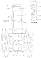
- the device constitutes a flattened housing ( 1 ).
- the two short sides ( 2 ) of which can be raised so that the four sides form a rectangular parallelepiped with the upper ( 9 ) and lower ( 11 ) faces.
- the flaps ( 3-4 ) are folded inside the housing ( 1 ), thus protecting the optical system ( 5 ) and the windows ( 13 ) from external aggressions when the stereoscope is in the storage position.
- this same box comprises two flaps ( 3 ) and ( 4 ) which unfold according to the folds ( 22 ).
- the shutter ( 3 ) comprises the optical system ( 5 ), and the shutter ( 4 ), the diffuser and the stereoscopic images ( 6 ).
- the pins ( 7 ) are placed in the perforations ( 8 ).
- the free edges of the two flaps ( 3 -4 ) on which the pins ( 7 ) are located, are curved, which causes a spring effect on the upper ( 9 ) or lower ( 11 ) face when the flaps are raised, favoring thus fitting and maintaining the lugs ( 7 ) in the perforations ( 8 ), and the correct positioning of the upper ( 9 ) or lower ( 11 ) face on the free and curved edge of the flaps ( 3-4 ), thus limiting the entry of stray light into the housing ( 1 ).
- the direction of the fibers of the cardboard is parallel to the fold lines ( 22 ).
- the two sides ( 2 ) protrude relative to the flaps ( 3-4 ), thus forming blinders ( 2 ' ) which limit the passage of stray light when observing stereoscopic images.
- the dotted line in FIG. 4 represents a variant enabling the views ( 6 ) fixed on a support ( 6 ' ) to be changed by sliding them into the slot ( 18 ).
- the lug ( 19 ) is placed in a perforation ( 20 ) (visible in Figures 6 and 7 ) located in the bottom of the housing, allowing the vertical maintenance of the interchangeable card.
- An opening ( 10 ) allows passage of the observer's nose. It is located in the center of the flap ( 3 ) and extends on the underside ( 11 ).
- this opening ( 10 ) also provides access to the flap ( 3 ) and ( 4 ) from the inside, so as to unfold them.
- the cutting and printing of the developed part of the case are carried out with the conventional techniques of the serial cutting of the cardboard boxes, and of the printing press.
- the tongue ( 12 ) is glued or fitted onto the zone ( 12 ' ) of the lower face ( 11 ).
- the images plus their diffuser and the lenses are mounted sandwiched, respectively between the faces ( 4 ' ) and ( 4 " ) of the shutter ( 4 ), and ( 3' ) & ( 3" ) of the shutter ( 3 ), after folding the folds ( 17 ), thus forming the pins ( 7 ) of the flaps ( 3-4 ).
- the cut windows ( 13 ) of the faces ( 4 ' ) and ( 4 " ) frame the views.
- the number of pins can vary.
- the faces ( 3 " ) and / or ( 4" ) can be deleted.
- the lenses and / or the views are then fixed directly on the faces ( 3 ' ) and / or ( 4' ).
- the perforations ( 14 ) are used when mounting lenses and images. This tracking system is flexible depending on the optics and views used.
- Figure 8 shows the shape of the optical piece of injected plastic.
- the lugs ( 7a ) are integrated into the part, which also has raised pins ( 15 ) for placement.
- a slight bead ( 21 ) will protrude from the shutter ( 3 ), on which the nose of the observer will come to rest, thus avoiding traces of perspiration on the cardboard.
- the case in the position of use will have dimensions of the order of 15 cm long, 9 cm wide and 4 cm high.
- the present invention is particularly intended for advertising and promotional applications. It can also serve as a communication tool, a teaching and educational tool, and a support for various publications.
Landscapes
- Physics & Mathematics (AREA)
- General Physics & Mathematics (AREA)
- Optics & Photonics (AREA)
- Cartons (AREA)
Claims (8)
- Zusammenklappbares Stereoskop (1), in einem Stück aus Karton oder einem anderen faltbaren Material gefertigt; in einer Art und Weise gefaltet und geklebt oder zusammengesteckt, daß sich eine Ober- (9) und eine Unterseite (11), sowie vier Seitenteile, die sich immer zwei und zwei gegenüberliegen (2,3-4), bilden. Dabei tragen von zwei sich gegenüberliegenden Seiten (34) auf der gleichen Ebene, die eine Seite (3) das optische System (5) und die andere Seite (4) zwei für das einfallende Licht mit lichtverteilendem Film bestückte Sichtfenster (13), an denen gleichzeitig auch der Filmstreifen mit den stereoskopischen Aufnahmen (6) auf Dauer oder abnehmbar befestigt ist. Zwei sich gegenüberliegende Seiten (3-4) stellen von jeweils der Ober- (9) oder der Unterseite (11) durch eine vorgegebene Faltung abgehende Klappe dar, während die zwei anderen sich gegenüberliegenden Seiten (2) sowohl mit der Ober-(9) und Unterseite (11) durch eine vorgegebene Faltung verbunden sind. Somit stellt der Bildbetrachter in Ablageposition eine auf den beiden letzteren sich gegenüberliegenden Seiten (2) abgeflachte Schachtel dar. Zur Benutzung müssen die zwei Letztgenannten sich gegenüberliegenden Seiten (2) aufgestellt werden. Auf diese Weise erhält die Schachtel (1) ihr Volumen und die beiden Klappen (3-4), die mit den Zapfen (7) am oberen freien Rand der Klappen (3-4), der Faltlinie gegenüberliegend, im Schachtelinneren gefaltet geruht haben, gleiten ebenfalls in eine Position, bei der sich die Klappe seiner Faltlinie gegenüber dank der Zapfen, die sich in die Perforationen (8) fügen, jeweils mit der Ober- (9) oder Unterseite (11) verbindet,
dadurch gekennzeichnet, daß sein optisches System (5) und die zwei Sichtfenster (13) auf den Klappen (3-4), die zu deren Schutz in Ablageposition in das Schachtelinnere (1) geklappt werden können und deren, der Faltlinie gegenüberliegende, obere gerundete Rand durch seine Form einen Sprungfedereffekt auf die Ober- (9) oder Unterseite (11) der Schachtel (1) ausübt, welche ihrerseits die Perforationen (8) für die dazugehörigen Zapfen (7), am oberen freien Rand der Klappen (3-4) sichtbar wenn entfaltet, aufweisen. Diese Rundung spielt eine entscheidende Rolle sowohl für die Verbindung und den allgemeinen Halt der Zapfen (7) in den Perforationen (8), als auch die Anschmiegbarkeit der Ober- (9) oder Unterseite (11) an besagtem oberen runden Rand der Klappen (3-4) und schließt störenden Lichteinfall in die Bildbetrachterschachtel (1) weitgehendst aus. - Stereoskop nach Anspruch 1 dadurch gekennzeichnet, daß die zwei sich gegenüberliegenden Seiten (2) über die Klappen (3-4) hinausragen um eine Art Visir (2') zu bilden, das dazu dient, die stereoskopischen Aufnahmen unter Ausschluß störenden Lichteinfalles betrachten zu können.
- Stereoskop nach einem der Ansprüche 1 und 2, dadurch gekennzeichnet, daß die beiden Klappen (3-4) durch ihre Faltlinie (22) mit der Unterseite (11) verbunden sind und mindestens einen Zapfen (7) auf dem jeweiligen freien oberen Rand aufweisen.
- Stereoskop nach einem der Ansprüche 1 bis 3, dadurch gekennzeichnet, daß die zwei Sichtfenster (13) in beiden Hälften (4'-4") der Klappe (4) eine über die andere, endsprechend der Faltlinie (17), gefaltet sind und welche wenigstens ein Verbindungsstück zwischen den Hälften (4'4") aufweisen, welches die Aufgabe des Zapfens (7) übernimmt.
- Stereoskop nach einem der Ansprüche 1 bis 4, dadurch gekennzeichnet, daß die Klappe (4) mindestens einen Lichtverteiler in den Sichtfenstern (13) trägt.
- Stereoskop nach einem der Ansprüche 1 bis 5, dadurch gekennzeichnet, daß das optische System (5) aus einem eingespritzten Plastikstück besteht, das Zapfen (7a), einen Wulst (21) im Ausschnitt für die Nase, über den Klappenrand (3) an dem es befestigt wird hinausreichend und kleine Späne zur Justierung (15) aufweist.
- Stereoskop nach Anspruch 4, dadurch gekennzeichnet, daß die stereoskopischen Aufnahmen (6) zwischen die Hälften (4'-4") der Klappe (4) geklemmt und von Sichtfenstern (13) gerahmt werden.
- Stereoskop nach einem der Ansprüche 1 bis 6, dadurch gekennzeichnet, dass die stereoskopischen Aufnahmen (6) sich auf einem unabhängigen Träger (6') aus Karton oder anderem Material befinden, der mit einem Zapfen (19) versehen ist, welcher vertikal in die Bodenperforation (20) auf der Unterseite (11) der Schachtel (1) gleitet. Diese Träger sind auswechselbar und werden durch einen Schlitz (18) in der Oberseite (9) sowohl eingelegt wie herausgenommen.
Applications Claiming Priority (3)
| Application Number | Priority Date | Filing Date | Title |
|---|---|---|---|
| FR9306381A FR2705794B1 (fr) | 1993-05-27 | 1993-05-27 | Stéréoscope pliable. |
| FR9306381 | 1993-05-27 | ||
| PCT/FR1994/000623 WO1994028453A1 (fr) | 1993-05-27 | 1994-05-26 | Stereoscope pliable |
Publications (2)
| Publication Number | Publication Date |
|---|---|
| EP0700531A1 EP0700531A1 (de) | 1996-03-13 |
| EP0700531B1 true EP0700531B1 (de) | 1997-03-12 |
Family
ID=9447518
Family Applications (1)
| Application Number | Title | Priority Date | Filing Date |
|---|---|---|---|
| EP94917062A Expired - Lifetime EP0700531B1 (de) | 1993-05-27 | 1994-05-26 | Faltbares stereoskop |
Country Status (4)
| Country | Link |
|---|---|
| EP (1) | EP0700531B1 (de) |
| DE (1) | DE69402068T2 (de) |
| FR (1) | FR2705794B1 (de) |
| WO (1) | WO1994028453A1 (de) |
Cited By (1)
| Publication number | Priority date | Publication date | Assignee | Title |
|---|---|---|---|---|
| DE102015000354A1 (de) | 2015-01-20 | 2016-07-21 | Can Ansay | An einer Baseballkappe montiretes Smartphone-Stereoskop |
Families Citing this family (5)
| Publication number | Priority date | Publication date | Assignee | Title |
|---|---|---|---|---|
| EP0708350A1 (de) * | 1994-10-19 | 1996-04-24 | Pieter Joannes Hendricus Evers | Betrachter, insbesondere Stereobetrachter, als auch ein ebenes Blatt hierfür, insbesondere hergestellt aus einem leicht biegsamen Werkstoff |
| US5940210A (en) * | 1995-05-12 | 1999-08-17 | Kassawat; Samer | Collapsible stereoscopic viewer |
| AT1158U1 (de) * | 1995-11-28 | 1996-11-25 | Poetscher Johannes | Einrichtung zur stereoskopischen betrachtung von bildern |
| CN108415159A (zh) * | 2017-02-10 | 2018-08-17 | 浙江唯见科技有限公司 | 一种vr眼镜 |
| DE202017006179U1 (de) | 2017-11-30 | 2018-01-31 | Can Ansay | Elektrische Munddusche mit auffüllbarem Wassertank, welche durch ein Röhrchen verlängert mit der Hand geführt die Reinigung des Anus auf der Klobrille sitzend erleichtert |
Family Cites Families (12)
| Publication number | Priority date | Publication date | Assignee | Title |
|---|---|---|---|---|
| GB813466A (en) * | 1956-09-20 | 1959-05-13 | Commercial Three Dimensional C | Improvements in or relating to stereoscopic picture viewing devices |
| US2696754A (en) * | 1951-07-28 | 1954-12-14 | Paul O Mamock | Folding stereoscope |
| US2715853A (en) * | 1954-04-21 | 1955-08-23 | Viewmailer Company | Collapsible stereoscopic viewer |
| US2794367A (en) * | 1954-08-03 | 1957-06-04 | Richard L Turner | Foldable stereoscope device for viewing stereoscopic transparencies and prints |
| US2872844A (en) * | 1956-05-04 | 1959-02-10 | Sidney Van Tuyl | Universal collapsible transparency viewer |
| GB824873A (en) * | 1957-03-01 | 1959-12-09 | David Mackane Watt | Improvements in or relating to viewing devices |
| US2919509A (en) * | 1958-01-31 | 1960-01-05 | Carl H Strandberg | Film frame or slide packaging box and viewer |
| FR1262757A (fr) * | 1960-05-03 | 1961-06-05 | Stereostar Italiana Di Fernand | Dispositif stéréoscopique repliable en forme de carte postale |
| JPS6027371Y2 (ja) * | 1977-10-03 | 1985-08-19 | 東京写真株式会社 | 折畳ステレオビユア− |
| US5000543A (en) * | 1989-04-10 | 1991-03-19 | James Curtin | 3-D viewers made from sheet materials |
| DE8909969U1 (de) * | 1989-08-19 | 1989-10-26 | Wunschik, Herbert, 6927 Bad Rappenau | Dia-Betrachter |
| DE9108339U1 (de) * | 1991-07-05 | 1991-09-26 | Refeka Werbemittel GmbH, 85551 Kirchheim | Bildbetrachter |
-
1993
- 1993-05-27 FR FR9306381A patent/FR2705794B1/fr not_active Expired - Fee Related
-
1994
- 1994-05-26 DE DE69402068T patent/DE69402068T2/de not_active Expired - Fee Related
- 1994-05-26 WO PCT/FR1994/000623 patent/WO1994028453A1/fr not_active Ceased
- 1994-05-26 EP EP94917062A patent/EP0700531B1/de not_active Expired - Lifetime
Cited By (2)
| Publication number | Priority date | Publication date | Assignee | Title |
|---|---|---|---|---|
| DE102015000354A1 (de) | 2015-01-20 | 2016-07-21 | Can Ansay | An einer Baseballkappe montiretes Smartphone-Stereoskop |
| WO2016116501A1 (de) | 2015-01-20 | 2016-07-28 | Ansay Can | Smartphone-stereoskop |
Also Published As
| Publication number | Publication date |
|---|---|
| DE69402068T2 (de) | 1997-10-30 |
| EP0700531A1 (de) | 1996-03-13 |
| FR2705794A1 (fr) | 1994-12-02 |
| FR2705794B1 (fr) | 1995-10-13 |
| WO1994028453A1 (fr) | 1994-12-08 |
| DE69402068D1 (de) | 1997-04-17 |
Similar Documents
| Publication | Publication Date | Title |
|---|---|---|
| EP2870502B1 (de) | Zusammenklappbarer stereoskopischer betrachter | |
| US6449891B1 (en) | Presentation apparatus for artwork | |
| EP0116491B1 (de) | Gerät zur Betrachtung von Stereopaaren auf einer an sich bekannten Stereokarte | |
| WO1994028453A1 (fr) | Stereoscope pliable | |
| US4782611A (en) | One-piece foldable frame assembly | |
| US4819354A (en) | One-piece foldable frame assembly | |
| FR3050544B1 (fr) | Boitier, flan, ensemble de flans et dispositif pour projection d'images virtuelles, et procede de montage d'un tel boitier. | |
| US2696754A (en) | Folding stereoscope | |
| FR2558605A1 (fr) | Dispositif pour visionner une vue stereoscopique disposee en couple | |
| US9188724B2 (en) | Image viewing device | |
| EP0918242A1 (de) | Vorrichtung zur stereoskopischen Betrachtung | |
| JP6926498B2 (ja) | 簡易3次元ビューワ | |
| FR2715234A1 (fr) | Dispositif déployable permettant de visionner des vues stéréoscopiques montés en couple dans des caches standards. | |
| NZ329640A (en) | Foldable stereoscope comprising a box with two windows, lugs, flaps and fold lines | |
| FR2828745A1 (fr) | Visionneuse pliable en carton, permettant d'observer des anaglyphes ou des stereogrammes, images doubles donnant la sensation de relief, ces images etant reproduites sur un support opaque | |
| JP6116265B2 (ja) | 偏光眼鏡の試着用ディスプレー装置 | |
| CN2735369Y (zh) | 一种简易立体镜 | |
| EP0237364A1 (de) | Entfaltbare Vorrichtung zur Betrachtung eines stereoskopischen Bildpaares | |
| WO2002023519A1 (en) | Collapsible folding stereographic viewer and printed media formats | |
| JP3216718U (ja) | 空間映像結像装置 | |
| FR2714188A1 (fr) | Stéréoscope déployable. | |
| EP0970413B1 (de) | Säule aus pappe für edv-endgerät | |
| FR2732778A1 (fr) | Dispositif de vision stereoscopique pliable | |
| EP1156355A1 (de) | Faltbare Vorrichtung, geeignet für stereoskopische Betrachtung mit einem einzigen Spiegel, wobei die Vorrichtung beim Entfalten entlang einer winkelhalbierenden Fläche nicht permanent deformiert wird | |
| EP1255152A2 (de) | Faltschachtel umwandelbar in ein stereoskopisches Betrachtungssystem |
Legal Events
| Date | Code | Title | Description |
|---|---|---|---|
| PUAI | Public reference made under article 153(3) epc to a published international application that has entered the european phase |
Free format text: ORIGINAL CODE: 0009012 |
|
| 17P | Request for examination filed |
Effective date: 19951226 |
|
| AK | Designated contracting states |
Kind code of ref document: A1 Designated state(s): BE CH DE DK ES GB GR IT LI NL PT |
|
| GRAG | Despatch of communication of intention to grant |
Free format text: ORIGINAL CODE: EPIDOS AGRA |
|
| 17Q | First examination report despatched |
Effective date: 19960712 |
|
| GRAH | Despatch of communication of intention to grant a patent |
Free format text: ORIGINAL CODE: EPIDOS IGRA |
|
| GRAH | Despatch of communication of intention to grant a patent |
Free format text: ORIGINAL CODE: EPIDOS IGRA |
|
| GRAA | (expected) grant |
Free format text: ORIGINAL CODE: 0009210 |
|
| AK | Designated contracting states |
Kind code of ref document: B1 Designated state(s): BE CH DE DK ES GB GR IT LI NL PT |
|
| PG25 | Lapsed in a contracting state [announced via postgrant information from national office to epo] |
Ref country code: NL Free format text: LAPSE BECAUSE OF FAILURE TO SUBMIT A TRANSLATION OF THE DESCRIPTION OR TO PAY THE FEE WITHIN THE PRESCRIBED TIME-LIMIT Effective date: 19970312 Ref country code: IT Free format text: LAPSE BECAUSE OF FAILURE TO SUBMIT A TRANSLATION OF THE DESCRIPTION OR TO PAY THE FEE WITHIN THE PRE;WARNING: LAPSES OF ITALIAN PATENTS WITH EFFECTIVE DATE BEFORE 2007 MAY HAVE OCCURRED AT ANY TIME BEFORE 2007. THE CORRECT EFFECTIVE DATE MAY BE DIFFERENT FROM THE ONE RECORDED.SCRIBED TIME-LIMIT Effective date: 19970312 Ref country code: GR Free format text: LAPSE BECAUSE OF FAILURE TO SUBMIT A TRANSLATION OF THE DESCRIPTION OR TO PAY THE FEE WITHIN THE PRESCRIBED TIME-LIMIT Effective date: 19970312 Ref country code: GB Effective date: 19970312 Ref country code: ES Free format text: THE PATENT HAS BEEN ANNULLED BY A DECISION OF A NATIONAL AUTHORITY Effective date: 19970312 Ref country code: DK Effective date: 19970312 |
|
| REG | Reference to a national code |
Ref country code: CH Ref legal event code: EP |
|
| REF | Corresponds to: |
Ref document number: 69402068 Country of ref document: DE Date of ref document: 19970417 |
|
| PG25 | Lapsed in a contracting state [announced via postgrant information from national office to epo] |
Ref country code: LI Free format text: LAPSE BECAUSE OF NON-PAYMENT OF DUE FEES Effective date: 19970531 Ref country code: CH Free format text: LAPSE BECAUSE OF NON-PAYMENT OF DUE FEES Effective date: 19970531 |
|
| PG25 | Lapsed in a contracting state [announced via postgrant information from national office to epo] |
Ref country code: PT Effective date: 19970612 |
|
| NLV1 | Nl: lapsed or annulled due to failure to fulfill the requirements of art. 29p and 29m of the patents act | ||
| GBV | Gb: ep patent (uk) treated as always having been void in accordance with gb section 77(7)/1977 [no translation filed] |
Effective date: 19970312 |
|
| REG | Reference to a national code |
Ref country code: CH Ref legal event code: PL |
|
| PLBE | No opposition filed within time limit |
Free format text: ORIGINAL CODE: 0009261 |
|
| STAA | Information on the status of an ep patent application or granted ep patent |
Free format text: STATUS: NO OPPOSITION FILED WITHIN TIME LIMIT |
|
| 26N | No opposition filed | ||
| PGFP | Annual fee paid to national office [announced via postgrant information from national office to epo] |
Ref country code: BE Payment date: 19980617 Year of fee payment: 5 |
|
| PGFP | Annual fee paid to national office [announced via postgrant information from national office to epo] |
Ref country code: DE Payment date: 19981218 Year of fee payment: 5 |
|
| PG25 | Lapsed in a contracting state [announced via postgrant information from national office to epo] |
Ref country code: BE Free format text: LAPSE BECAUSE OF NON-PAYMENT OF DUE FEES Effective date: 19990531 |
|
| BERE | Be: lapsed |
Owner name: COACHE OLIVIER Effective date: 19990531 |
|
| PG25 | Lapsed in a contracting state [announced via postgrant information from national office to epo] |
Ref country code: DE Free format text: LAPSE BECAUSE OF NON-PAYMENT OF DUE FEES Effective date: 20000301 |