EP0700537B1 - Systemes de commande a distance - Google Patents
Systemes de commande a distance Download PDFInfo
- Publication number
- EP0700537B1 EP0700537B1 EP94915631A EP94915631A EP0700537B1 EP 0700537 B1 EP0700537 B1 EP 0700537B1 EP 94915631 A EP94915631 A EP 94915631A EP 94915631 A EP94915631 A EP 94915631A EP 0700537 B1 EP0700537 B1 EP 0700537B1
- Authority
- EP
- European Patent Office
- Prior art keywords
- module
- data packet
- controller
- modules
- instruction
- Prior art date
- Legal status (The legal status is an assumption and is not a legal conclusion. Google has not performed a legal analysis and makes no representation as to the accuracy of the status listed.)
- Expired - Lifetime
Links
- 238000010586 diagram Methods 0.000 description 3
- 230000001934 delay Effects 0.000 description 1
- 238000010438 heat treatment Methods 0.000 description 1
- 230000036039 immunity Effects 0.000 description 1
Images
Classifications
-
- H—ELECTRICITY
- H04—ELECTRIC COMMUNICATION TECHNIQUE
- H04Q—SELECTING
- H04Q9/00—Arrangements in telecontrol or telemetry systems for selectively calling a substation from a main station, in which substation desired apparatus is selected for applying a control signal thereto or for obtaining measured values therefrom
- H04Q9/14—Calling by using pulses
- H04Q9/16—Calling by using pulses by predetermined number of pulses
Definitions
- This invention relates to remote control systems comprising a central controller (Master) and a plurality of remote modules (Slaves) responsive to instructions from the controller.
- Master central controller
- Slaves remote modules
- Systems of this type are used, for example, for controlling lighting, heating, or ventilating in large buildings.
- the controller can send status enquiries to all the remote modules in the building and can receive back from these modules data as to the status of the systems they are controlling, e.g. is a light on or off.
- the controller may then send out instructions to specific modules to cause them to control the apparatus (lights), to which they are connected in a desired manner.
- modules are connected in a ring and a token is passed from module to module.
- a status enquiry can be sent from the controller to that module and the status data sent back to the controller.
- An instruction may then be sent to that module if it is desired to change its status.
- all the modules are connected in series with the controller, and a data packet, including instructions for modules, passes through each the module in turn.
- Part of the data packet comprises a module counter which is incremented as the packet passes through each module.
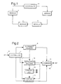
- Figure 1 shows how a plurality of modules 2 are connected in series with a controller 4 in a loop.
- Each module and the controller has a serial input and a serial output.
- a data packet generated by the controller passes from its serial output to the serial input of the first module in the loop.
- the data passes through the module, one byte at a time, and is then available at the output of the module. There is, however, a lag between input and output of, for example, 3 bits.
- the front end of a data packet will have left a module before the end has entered that module. Once a data packet has passed through all the modules in the loop it returns to the controller 4.
- the time taken for the head of a data packet to pass round a ring of modules will be (module delay) x (number of modules), i.e. at 9600 baud with a 3 bit module delay the head of a data packet will travel right round the ring in about 18ms.
- the data packet, (known as the notepad) sent out by the controller comprises three main portions. These are an instruction portion, a module counter, and an address and data portion. The whole packet is terminated by an end code.
- the instruction portion is then decoded and acted upon if it is addressed to the module number indicated by the current value of the module counter.
- the instruction can be an instruction to, for example, switch on a single light or a batch of lights, i.e. all those between modules 1 and 8.
- it may be a status enquiry of the modules which will cause the status of each module in turn to be written into the address and data portion of the notepad if there has been a change in module status.
- the address and data portion increase in size as more information is written into it.
- the module comprises an input 6 receiving data packets which have passed through other modules in the chain and which were originally generated by the controller. Each packet passes to a distributor which sends the module counter data to a counter incrementor 8.
- the distributor 7 sends the instruction portion of the notepad to an instruction decoder 10 and the address and data portion to a status decoder 12.
- the counter incrementor 8 has an output coupled to the instruction decoder 10 and to the status decoder 12. Thus the instruction decoder and the status decoder have available the current value of the module counter.
- the instruction decoder 10 decodes the instruction portion of the notepad.
- this instruction may comprise, for example, turn on lights.
- the data section of the address and data portion of the notepad will include information as to the lights to be switched on.
- the instruction decoder can compute whether or not the instruction is to be acted upon by that particular module. If it is then the relevant instruction is sent to a control unit 14 which will implements the instruction.
- the instruction decoder sends an enable signal to the status decoder 12 which receives data from the control unit as to its status.
- the status decoder also receives the current value of the module counter and the address and data portion of the notepad.
- the status decoder will write into the address and data portion the current module address and the status of the apparatus which it is controlling. Usually this will only happen if there has been a change in status since the last enquiry. Thus as the notepad passes around the ring the address and data portion of the notepad will increase in size.
- the current value of the module counter, the instruction, and the address and data portion are recombined in a combiner 16 and then passed to the next module in the chain via an output 18.
- Each module may be implemented in a conventional gate array on a single chip.
- a microprocessor could be used for a more intelligent module.
- each module in use each module is able to work out its address (the module counter value) from its position in the ring, i.e. the data which arrives at the ring includes a module counter which that module uses to derive its own address.
- the address the module counter value
- the data which arrives at the ring includes a module counter which that module uses to derive its own address.
- a switch status notepad is 10 bytes long and is transmitted round the ring at 9600 baud with a delay of 3 bits per module.
- the notepad includes a reset sequence, headers, the module counter and the inverse of every byte as an error check.
- a module For a module to add a switch status onto the end of a notepad as it passes through a module it first changes the end of the notepad byte to a continue byte. It then adds a module number byte of status information and a new end of notepad byte. This means that the three bytes and their inverses are added on for each module that has a change of status.
- a switch notepad can be generated to control the lights to be switched.
- This resultant notepad is 10 bytes long plus 4 bytes for every module to be addressed. If 6 modules needed to turn lamps on or off this would require a 34 byte notepad which would take approximately 34ms to pass round the ring. Thus the total time from a switch being pressed to a light being turned on would be about 75ms. In practice, however, longer is required because delays are introduced to improve immunity to switching noise etc.
- the controller can issue a command notepad asking these modules to varify their status. This could be done 10 or 20 times and the system could still easily respond within 200ms. This is a check on the status received.
Landscapes
- Engineering & Computer Science (AREA)
- Computer Networks & Wireless Communication (AREA)
- Selective Calling Equipment (AREA)
- Small-Scale Networks (AREA)
Claims (6)
- Système de commande à distance comportant un dispositif de commande (4) et plusieurs modules éloignés (2) connectés en série avec le dispositif de commande, dans lequel un paquet de données, qui comprend une partie à compteur de module et une partie à instructions formée d'instructions pour des modules individuels, est généré par le dispositif de commande et passe d'un module à l'autre, chaque module comporte des moyens (8) destinés à incrémenter la partie à compteur de module avant de faire passer le paquet de données au module suivant, et chaque module comporte en outre des moyens (10, 12) destinés à dériver une adresse de module pour ce module à partir de la valeur du compteur de module à ce module, et des moyens destinés à exécuter des instructions dans la partie à instructions pour ce module.
- Système de commande à distance selon la revendication 1, dans lequel la partie à instructions du paquet de données comporte une demande d'état pour les modules dans le système.
- Système de commande à distance selon la revendication 1 ou 2, dans lequel chaque module comporte des moyens (16) destinés à additionner des données d'état pour ce module au paquet de données avant que le paquet de données soit passé au module suivant, les données d'état comprenant l'adresse de module dérivée.
- Système de commande à distance selon la revendication 1, 2 ou 3, dans lequel les moyens destinés à exécuter des instructions dans chaque module comportent des moyens (10) destinés à décoder une instruction reçue dans un paquet de données et des moyens (14) destinés à exécuter l'instruction en dépendance de la comparaison entre une adresse de module incluse dans le paquet de données et l'adresse de module dérivée par ce module.
- Système de commande à distance selon l'une quelconque des revendications précédentes, dans lequel les modules sont connectés dans un anneau avec le dispositif de commande (4), grâce à quoi un paquet de données généré par le dispositif de commande passe tour à tour à travers chaque module (2) avant de revenir au dispositif de commande.
- Module (2) destiné à être utilisé dans un système de commande à distance, comportant un moyen d'entrée (6) destiné à recevoir un paquet de données et un moyen de sortie (18) destiné à envoyer un paquet de données, dans lequel chaque paquet de données comprend une partie à compteur de module et une partie à instructions formée d'instructions pour des modules individuels, le module comportant des moyens (8) destinés à incrémenter le compteur du module lorsqu'il passe à travers le module et des moyens (10, 12) destinés à dériver une adresse de module pour ce module à partir de la valeur du compteur de module à ce module à chaque fois qu'un paquet de données est reçu, et des moyens destinés à exécuter des instructions pour ce module, reçues dans le paquet de données.
Applications Claiming Priority (3)
| Application Number | Priority Date | Filing Date | Title |
|---|---|---|---|
| GB9310845 | 1993-05-26 | ||
| GB9310845A GB2278473B (en) | 1993-05-26 | 1993-05-26 | Remote control systems |
| PCT/GB1994/001086 WO1994028471A1 (fr) | 1993-05-26 | 1994-05-20 | Systemes de commande a distance |
Publications (2)
| Publication Number | Publication Date |
|---|---|
| EP0700537A1 EP0700537A1 (fr) | 1996-03-13 |
| EP0700537B1 true EP0700537B1 (fr) | 1998-08-19 |
Family
ID=10736148
Family Applications (1)
| Application Number | Title | Priority Date | Filing Date |
|---|---|---|---|
| EP94915631A Expired - Lifetime EP0700537B1 (fr) | 1993-05-26 | 1994-05-20 | Systemes de commande a distance |
Country Status (7)
| Country | Link |
|---|---|
| EP (1) | EP0700537B1 (fr) |
| JP (1) | JPH09500498A (fr) |
| CN (1) | CN1124527A (fr) |
| DE (1) | DE69412607T2 (fr) |
| ES (1) | ES2122278T3 (fr) |
| GB (1) | GB2278473B (fr) |
| WO (1) | WO1994028471A1 (fr) |
Families Citing this family (3)
| Publication number | Priority date | Publication date | Assignee | Title |
|---|---|---|---|---|
| US5802389A (en) * | 1994-12-29 | 1998-09-01 | Siemens Energy & Automation, Inc. | Expansion module address method and apparatus for a programmable logic controller |
| GB2307321A (en) | 1995-11-15 | 1997-05-21 | Delmatic Ltd | Failed light detector |
| CN101483950B (zh) * | 2008-01-09 | 2012-05-23 | 聚积科技股份有限公司 | 运作远程多点控制系统的方法 |
Family Cites Families (3)
| Publication number | Priority date | Publication date | Assignee | Title |
|---|---|---|---|---|
| GB2180972A (en) * | 1985-09-27 | 1987-04-08 | Philips Electronic Associated | Generating addresses for circuit units |
| US4730309A (en) * | 1986-08-25 | 1988-03-08 | Amp Incorporated | Data transmission station |
| US5185866A (en) * | 1988-12-30 | 1993-02-09 | Pitney Bowes Inc. | Dual mode communication among plurality of processors using three distinct data channels each having different function and operations |
-
1993
- 1993-05-26 GB GB9310845A patent/GB2278473B/en not_active Expired - Fee Related
-
1994
- 1994-05-20 ES ES94915631T patent/ES2122278T3/es not_active Expired - Lifetime
- 1994-05-20 WO PCT/GB1994/001086 patent/WO1994028471A1/fr not_active Ceased
- 1994-05-20 EP EP94915631A patent/EP0700537B1/fr not_active Expired - Lifetime
- 1994-05-20 JP JP7500350A patent/JPH09500498A/ja active Pending
- 1994-05-20 CN CN 94192248 patent/CN1124527A/zh active Pending
- 1994-05-20 DE DE69412607T patent/DE69412607T2/de not_active Expired - Fee Related
Also Published As
| Publication number | Publication date |
|---|---|
| GB2278473A (en) | 1994-11-30 |
| WO1994028471A1 (fr) | 1994-12-08 |
| DE69412607T2 (de) | 1999-02-25 |
| CN1124527A (zh) | 1996-06-12 |
| ES2122278T3 (es) | 1998-12-16 |
| GB2278473B (en) | 1997-05-07 |
| GB9310845D0 (en) | 1993-07-14 |
| EP0700537A1 (fr) | 1996-03-13 |
| JPH09500498A (ja) | 1997-01-14 |
| DE69412607D1 (de) | 1998-09-24 |
Similar Documents
| Publication | Publication Date | Title |
|---|---|---|
| AU626880B2 (en) | Peer-to-peer register exchange controller for plcs | |
| US5987532A (en) | Single-line, series connected, data transfer control system | |
| US4914654A (en) | Multiplex transmission system | |
| US4470110A (en) | System for distributed priority arbitration among several processing units competing for access to a common data channel | |
| US7664133B2 (en) | High level message priority assignment by a plurality of message-sending nodes sharing a signal bus | |
| US6704899B1 (en) | Method and device for secure transmission of data signals over a bus system | |
| CA1231458A (fr) | Dispositif pour controler le transfert d'instructions entre processeurs | |
| EP0700537B1 (fr) | Systemes de commande a distance | |
| JPS6098738A (ja) | アドレス割当方法 | |
| US6393020B1 (en) | Gated multi-drop communication system | |
| JPS62155646A (ja) | リンク制御装置 | |
| US6460096B1 (en) | Automatic serial bus transmission sequencer | |
| US4978953A (en) | Device for monitoring multiple digital data channels | |
| EP0569512A4 (en) | Packet transmission system and method utilizing both a data bus and dedicated control lines | |
| EP0495251B1 (fr) | Système de communication locale et de formation de trame avec un générateur d'adresse programmable | |
| EP1476986B1 (fr) | Appareil d'interface de controleur de communication d'informations et procede | |
| KR100514620B1 (ko) | 공기조화기의 제어 방법 | |
| JPH11136778A (ja) | Pcmハイウェイ拡張方式 | |
| SU1262513A1 (ru) | Устройство дл обмена информацией между электронными вычислительными машинами | |
| JPH0654368A (ja) | 電気機械式ロッキング・システムの装置を制御する方法 | |
| JP3074598B2 (ja) | データ交換装置 | |
| JP2785990B2 (ja) | 入出力ポートの状態管理機能を持ったパケット交換スイッチ | |
| JPH0311701B2 (fr) | ||
| JPH04177045A (ja) | 空調システムの自動アドレス制御装置 | |
| RU2020125387A (ru) | Способ и система организации обмена данными между электронными устройствами |
Legal Events
| Date | Code | Title | Description |
|---|---|---|---|
| PUAI | Public reference made under article 153(3) epc to a published international application that has entered the european phase |
Free format text: ORIGINAL CODE: 0009012 |
|
| 17P | Request for examination filed |
Effective date: 19951018 |
|
| AK | Designated contracting states |
Kind code of ref document: A1 Designated state(s): DE ES FR |
|
| 17Q | First examination report despatched |
Effective date: 19960604 |
|
| RBV | Designated contracting states (corrected) |
Designated state(s): DE ES FR |
|
| GRAG | Despatch of communication of intention to grant |
Free format text: ORIGINAL CODE: EPIDOS AGRA |
|
| GRAG | Despatch of communication of intention to grant |
Free format text: ORIGINAL CODE: EPIDOS AGRA |
|
| GRAH | Despatch of communication of intention to grant a patent |
Free format text: ORIGINAL CODE: EPIDOS IGRA |
|
| GRAH | Despatch of communication of intention to grant a patent |
Free format text: ORIGINAL CODE: EPIDOS IGRA |
|
| RAP1 | Party data changed (applicant data changed or rights of an application transferred) |
Owner name: DELMATIC LIMITED |
|
| GRAA | (expected) grant |
Free format text: ORIGINAL CODE: 0009210 |
|
| AK | Designated contracting states |
Kind code of ref document: B1 Designated state(s): DE ES FR |
|
| REF | Corresponds to: |
Ref document number: 69412607 Country of ref document: DE Date of ref document: 19980924 |
|
| ET | Fr: translation filed | ||
| REG | Reference to a national code |
Ref country code: ES Ref legal event code: FG2A Ref document number: 2122278 Country of ref document: ES Kind code of ref document: T3 |
|
| PGFP | Annual fee paid to national office [announced via postgrant information from national office to epo] |
Ref country code: FR Payment date: 19990511 Year of fee payment: 6 |
|
| PGFP | Annual fee paid to national office [announced via postgrant information from national office to epo] |
Ref country code: ES Payment date: 19990524 Year of fee payment: 6 |
|
| PGFP | Annual fee paid to national office [announced via postgrant information from national office to epo] |
Ref country code: DE Payment date: 19990525 Year of fee payment: 6 |
|
| PLBE | No opposition filed within time limit |
Free format text: ORIGINAL CODE: 0009261 |
|
| STAA | Information on the status of an ep patent application or granted ep patent |
Free format text: STATUS: NO OPPOSITION FILED WITHIN TIME LIMIT |
|
| 26N | No opposition filed | ||
| PG25 | Lapsed in a contracting state [announced via postgrant information from national office to epo] |
Ref country code: ES Free format text: THE PATENT HAS BEEN ANNULLED BY A DECISION OF A NATIONAL AUTHORITY Effective date: 20000522 |
|
| PG25 | Lapsed in a contracting state [announced via postgrant information from national office to epo] |
Ref country code: FR Free format text: LAPSE BECAUSE OF NON-PAYMENT OF DUE FEES Effective date: 20010131 |
|
| PG25 | Lapsed in a contracting state [announced via postgrant information from national office to epo] |
Ref country code: DE Free format text: LAPSE BECAUSE OF NON-PAYMENT OF DUE FEES Effective date: 20010301 |
|
| REG | Reference to a national code |
Ref country code: FR Ref legal event code: ST |
|
| REG | Reference to a national code |
Ref country code: ES Ref legal event code: FD2A Effective date: 20020204 |