EP0700705A1 - Procédé et dispositif pour la séparation d'un mélange pour distillation continue - Google Patents
Procédé et dispositif pour la séparation d'un mélange pour distillation continue Download PDFInfo
- Publication number
- EP0700705A1 EP0700705A1 EP95114134A EP95114134A EP0700705A1 EP 0700705 A1 EP0700705 A1 EP 0700705A1 EP 95114134 A EP95114134 A EP 95114134A EP 95114134 A EP95114134 A EP 95114134A EP 0700705 A1 EP0700705 A1 EP 0700705A1
- Authority
- EP
- European Patent Office
- Prior art keywords
- column
- distillation
- fed
- mixture
- columns
- Prior art date
- Legal status (The legal status is an assumption and is not a legal conclusion. Google has not performed a legal analysis and makes no representation as to the accuracy of the status listed.)
- Granted
Links
- 238000000034 method Methods 0.000 title claims abstract description 25
- 239000000203 mixture Substances 0.000 title claims description 36
- 238000000926 separation method Methods 0.000 title claims description 9
- 238000004821 distillation Methods 0.000 claims abstract description 95
- 230000008569 process Effects 0.000 claims abstract description 12
- 239000007788 liquid Substances 0.000 claims description 12
- 238000007700 distillative separation Methods 0.000 claims description 5
- 238000009833 condensation Methods 0.000 claims 3
- 230000005494 condensation Effects 0.000 claims 3
- 238000010992 reflux Methods 0.000 claims 1
- 239000003990 capacitor Substances 0.000 description 8
- LRHPLDYGYMQRHN-UHFFFAOYSA-N N-Butanol Chemical compound CCCCO LRHPLDYGYMQRHN-UHFFFAOYSA-N 0.000 description 5
- 238000009835 boiling Methods 0.000 description 5
- 230000008878 coupling Effects 0.000 description 5
- 238000010168 coupling process Methods 0.000 description 5
- 238000005859 coupling reaction Methods 0.000 description 5
- 239000000470 constituent Substances 0.000 description 4
- ZXEKIIBDNHEJCQ-UHFFFAOYSA-N isobutanol Chemical compound CC(C)CO ZXEKIIBDNHEJCQ-UHFFFAOYSA-N 0.000 description 4
- 238000004364 calculation method Methods 0.000 description 3
- 238000005265 energy consumption Methods 0.000 description 3
- 239000000126 substance Substances 0.000 description 3
- 230000000052 comparative effect Effects 0.000 description 1
- 238000004590 computer program Methods 0.000 description 1
- 238000000354 decomposition reaction Methods 0.000 description 1
- 230000010354 integration Effects 0.000 description 1
- 239000000463 material Substances 0.000 description 1
- 230000009467 reduction Effects 0.000 description 1
Images


Classifications
-
- B—PERFORMING OPERATIONS; TRANSPORTING
- B01—PHYSICAL OR CHEMICAL PROCESSES OR APPARATUS IN GENERAL
- B01D—SEPARATION
- B01D3/00—Distillation or related exchange processes in which liquids are contacted with gaseous media, e.g. stripping
- B01D3/14—Fractional distillation or use of a fractionation or rectification column
- B01D3/143—Fractional distillation or use of a fractionation or rectification column by two or more of a fractionation, separation or rectification step
- B01D3/146—Multiple effect distillation
Definitions
- the invention relates to a method and a device for the continuous distillative separation of a feed mixture into two fractions by means of two distillation columns.
- the distillation is usually carried out by feeding a feed mixture consisting of two constituents with different boiling temperatures into the central region of a distillation column.
- the low-boiling constituent can then be removed as distillate at the top end, the top end, of the column.
- the high-boiling constituent can be removed as a distillation residue at the bottom of the column, the bottom of the bottom.
- FIGS. 1 to 3 Various possibilities are known in the prior art for operating a plurality of distillation columns for separating a mixture, as illustrated in FIGS. 1 to 3. Such interconnections of several distillation columns are mainly used to expand the capacity of existing plants.
- 1 shows two distillation columns which are operated in parallel and independently of one another, an inflow of a mixture A, B being divided between the two columns and the separate constituents A and B being removed from both columns.
- 2 shows a connection of the distillation columns in a direct separation sequence, whereas 3 shows an interconnection of two distillation columns in inverse separation order.
- the bottom product or the top product of the first distillation column is fed to the second distillation column as a feed mixture.
- the thermal energy requirement can be improved compared to the arrangement shown in FIG. 1.
- two distillation columns are used, each of which is fed with a feed mixture in its central region.
- the two distillation columns are operated with different temperature profiles, which however overlap at least in some areas. That is to say that the top end of one distillation column is preferably in the middle of the temperature of the other distillation column, and the bottom end of a distillation column in a central area of the other distillation column.
- the temperature range of one distillation column can be completely contained in the temperature range of the other distillation column, or the temperature profiles only match in partial areas.
- the temperature profiles in the distillation columns can be different, so that one can only speak of a comparable temperature profile or temperature level in some areas, but not of complete agreement.
- the overlapping area is therefore the area between the connecting lines in the case of both distillation columns.
- the methods of the present invention can be used particularly advantageously when expanding the capacity of an existing distillation plant. If, for example, the capacity of an existing distillation column is to be doubled, this can be achieved by connecting to a second distillation column of the same capacity according to the invention, without doubling the required process energy expenditure.
- One line carries a liquid flow, whereas the other line carries a vapor flow.
- the thermodynamic coupling of both distillation columns can be further improved.
- thermodynamic coupling of two distillation columns to separate a two-substance mixture provides a total of two feed mixture inlets, one outlet for the low boiler and one outlet for the high boiler.
- the mixing ratio and process parameters, such as temperature and pressure, at the inlet mixture inputs can differ from one another, but are preferably approximately the same. This differs from the prior art arrangements discussed above, which require more than one exit each for the high boilers and the low boilers.
- a vapor stream enriched in high boilers is fed via a line 3 to the first distillation column 1, specifically above the feed point for the feed mixture.
- an High-boiling liquid stream supplied via a line 4 to the second distillation column 2, namely below the feed point of the feed mixture.
- a liquid stream is withdrawn from the first distillation column 1 in the area where the overhead vapor stream is fed from the line 3 to the second distillation column 2 and is fed via a line 7 to the upper end of the second distillation column 2.
- a vapor stream is separated from the second distillation column 2 in the area in which the bottom liquid stream from the distillation column 1 is fed in via line 4 and is fed in via line 8 at the lower end of the distillation column 1.
- both the low boiler A and the high boiler B at the top or bottom end of a distillation column 2 are removed.
- a condenser 5 and an evaporator 6 are also provided here at the removal points of the distillation products. In this exemplary embodiment, these are arranged accordingly at the top or bottom end of the second distillation column 2.
- a first distillation column 1 has a temperature profile which is contained in the temperature profile of the second distillation column 2. That is, the top temperature of the first distillation column 1 is higher or the same as the top temperature of the second distillation column 2, and the bottom temperature of the first distillation column 1 is lower or the same as the bottom temperature of the second distillation column 2.
- the feed mixture A, B becomes both distillation columns 1, 2 fed in their central area.
- a mixture enriched in low boilers is removed and via a line 3 to the second Distillation column 2 performed.
- a liquid stream enriched in high boilers is fed via a line 4 to the second distillation column 2.
- a liquid stream is additionally taken from the second distillation column 2 in the region of the feed point of the line 3 and fed to the upper end of the first distillation column 1 via a line 7.
- a vapor stream is divided into the second distillation column 2 in the region of the feed point of line 4 and fed in at the lower end of the first distillation column 1.
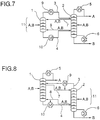
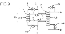
- the exemplary embodiment shown in FIG. 6 differs from the first exemplary embodiment in that a capacitor 9 is interposed in line 3 at the upper end of the temperature overlap region. It is also possible according to FIG. 8 to use a partial condenser and to feed the condensed liquid completely or partially to the top of the column 2. In addition, an evaporator 10 is interposed in the connecting line 4 at the lower end of the temperature overlap region. In this way, the thermodynamic efficiency can be increased further. The vapor stream from this evaporator can be introduced into column 2 (FIG. 6) or column 1 (FIG. 8).
- the exemplary embodiment shown in FIG. 7 or FIG. 9 differs from the second exemplary embodiment shown in FIG. 5, analogously to FIG. 6, in that a capacitor 9 is interposed in line 3 at the upper end of the temperature overlap region and in that the line 4 at the lower end of the temperature overlap area an evaporator 10 is interposed.
- the invention can be used in particular in the expansion of the capacity of already existing distillation plants.
- When expanding the capacity of an existing column efforts are made to continue using it for cost reasons. You build a second column and combine the functions of both columns. The possibilities of the prior art already mentioned are suitable for this.
- the selection of the most suitable column connection depends on the separation behavior of the mixture components, the required purities and the feed composition and must be examined in each individual case.
- the arrangement according to the invention of an additional column enables savings in both energy and investment costs, as will be shown below. It can also be used in cases where both columns are operated at different pressures.
- these column arrangements are also of interest as an alternative to a column with intermediate evaporators or intermediate condensers. They enable comparable measures for an energy network. If vapor compressors are used, there are several flexibly usable coupling points with a reduced temperature difference, which lead to lower drive powers.
- Circuit 1 1,096 kW
- Circuit 2 1,096 kW
- Circuit 3 1,141 kW
- Circuit 4 896 kW
- Circuit 1 5,554 kW Circuit 2: 2,604 kW Circuit 3: 2,613 kW Circuit 4: 1,389 kW
- the column switching according to the invention proves to be particularly advantageous. This is particularly important if the existing column is rather too short in terms of the number of plates and the required product purity.
- the column interconnection of the invention leads to an effective increase in the actually effective number of plates of the overall system with the same number of plates of the individual columns. This in turn leads to a reduction in energy requirements.
- the above examples for the decomposition of an n- / iso-butanol mixture for different numbers of separation stages make this very clear.
Landscapes
- Chemical & Material Sciences (AREA)
- Chemical Kinetics & Catalysis (AREA)
- Vaporization, Distillation, Condensation, Sublimation, And Cold Traps (AREA)
Applications Claiming Priority (2)
| Application Number | Priority Date | Filing Date | Title |
|---|---|---|---|
| DE4432172 | 1994-09-09 | ||
| DE4432172A DE4432172A1 (de) | 1994-09-09 | 1994-09-09 | Verfahren und Vorrichtung zur kontinuierlichen destillativen Trennung eines Gemisches |
Publications (2)
| Publication Number | Publication Date |
|---|---|
| EP0700705A1 true EP0700705A1 (fr) | 1996-03-13 |
| EP0700705B1 EP0700705B1 (fr) | 2002-04-17 |
Family
ID=6527833
Family Applications (1)
| Application Number | Title | Priority Date | Filing Date |
|---|---|---|---|
| EP95114134A Expired - Lifetime EP0700705B1 (fr) | 1994-09-09 | 1995-09-08 | Procédé pour la séparation d'un mélange pour distillation continue |
Country Status (3)
| Country | Link |
|---|---|
| EP (1) | EP0700705B1 (fr) |
| DE (2) | DE4432172A1 (fr) |
| ES (1) | ES2174886T3 (fr) |
Cited By (2)
| Publication number | Priority date | Publication date | Assignee | Title |
|---|---|---|---|---|
| EP0948983A3 (fr) * | 1998-04-08 | 1999-12-22 | Air Products And Chemicals, Inc. | Schémas de distillation améliorés pour des séparations de plusieurs constituants |
| EP0960640A3 (fr) * | 1998-05-26 | 2000-01-12 | Air Products And Chemicals, Inc. | Schémas de distillation opérables et efficaces pour des séparations de plusieurs composants |
Citations (1)
| Publication number | Priority date | Publication date | Assignee | Title |
|---|---|---|---|---|
| US3058893A (en) * | 1959-09-01 | 1962-10-16 | Exxon Research Engineering Co | Separation of multicomponent mixture in single tower |
-
1994
- 1994-09-09 DE DE4432172A patent/DE4432172A1/de not_active Withdrawn
-
1995
- 1995-09-08 ES ES95114134T patent/ES2174886T3/es not_active Expired - Lifetime
- 1995-09-08 EP EP95114134A patent/EP0700705B1/fr not_active Expired - Lifetime
- 1995-09-08 DE DE59510170T patent/DE59510170D1/de not_active Expired - Fee Related
Patent Citations (1)
| Publication number | Priority date | Publication date | Assignee | Title |
|---|---|---|---|---|
| US3058893A (en) * | 1959-09-01 | 1962-10-16 | Exxon Research Engineering Co | Separation of multicomponent mixture in single tower |
Non-Patent Citations (2)
| Title |
|---|
| GERD KABEL, ECKHART BLA UND JÜRGEN KÖHLER: "gestaltung destillativer trennungen unter einbeziehung thermodynamischer gesichtspunkte", CHEMIE INGENIEUR TECHNIK, vol. 61, no. 1, WEINHEIM, pages 16 - 25, XP000025551 * |
| GERD KAIBEL UND ECKHART BLA: "möglichkeiten zur prozeintegration bei destillativen trennverfahren", CHEMIE-INGENIEUR-TECHNIK, vol. 61, no. 2, WEINHEIM, pages 104 - 112, XP000036728 * |
Cited By (2)
| Publication number | Priority date | Publication date | Assignee | Title |
|---|---|---|---|---|
| EP0948983A3 (fr) * | 1998-04-08 | 1999-12-22 | Air Products And Chemicals, Inc. | Schémas de distillation améliorés pour des séparations de plusieurs constituants |
| EP0960640A3 (fr) * | 1998-05-26 | 2000-01-12 | Air Products And Chemicals, Inc. | Schémas de distillation opérables et efficaces pour des séparations de plusieurs composants |
Also Published As
| Publication number | Publication date |
|---|---|
| DE4432172A1 (de) | 1996-03-14 |
| DE59510170D1 (de) | 2002-05-23 |
| ES2174886T3 (es) | 2002-11-16 |
| EP0700705B1 (fr) | 2002-04-17 |
Similar Documents
| Publication | Publication Date | Title |
|---|---|---|
| DE19849651C2 (de) | Rektifizierkolonne für die Extraktivdestillation von eng- oder azeotrop siedenden Gemischen | |
| EP0299364B1 (fr) | Procédé et dispositif de séparation de l'air par rectification | |
| DE69926429T2 (de) | Destillationsverfahren und -vorrichtung zur Multikomponent-Trennung | |
| DE69911511T2 (de) | Herstellung von Argon durch ein kryogenisches Lufttrennungsverfahren | |
| DE1551581A1 (de) | Verfahren zum Abscheiden von Stickstoff aus Luft | |
| DE69515068T3 (de) | Atmospherisches Gastrennungsverfahren | |
| DE4443190A1 (de) | Verfahren und Vorrichtung zur Tieftemperaturzerlegung von Luft | |
| DE69405330T2 (de) | Selbstkühlendes Verfahren zur kryogenischen Fraktionierung und Reinigung von Gas, sowie Wärmetauscher zu seiner Durchführung | |
| DE2538472A1 (de) | Verfahren zur durchfuehrung einer mehrfachverdampfung | |
| DE2851815A1 (de) | Verfahren zur unterdruckfraktionierung einer eine schwere erdoelfraktion oder einen bei atmosphaerendruck gebildeten rueckstand enthaltenden komponente sowie eine vorrichtung zur durchfuehrung des verfahrens | |
| DE2521723B2 (de) | Verfahren und Vorrichtung zur Herstellung von reinem Argon durch Fraktionierung der Luft | |
| DE69208215T2 (de) | Wärmeintegrationzwischenkolonne für einen Multikolonnendestillationssystem | |
| EP0700705B1 (fr) | Procédé pour la séparation d'un mélange pour distillation continue | |
| EP0434959B1 (fr) | Procédé d'obtention simultanée de benzène purifié et de toluène purifié | |
| EP0228623B1 (fr) | Procédé de séparation d'hydrocarbures en C5+ d'un courant gazeux | |
| DE10018434B4 (de) | Anlage zur Gewinnung von Aromaten aus einem Aromaten und Nichtaromaten enthaltenden Kohlenwasserstoffgemisch | |
| EP0505723B1 (fr) | Procédé pour la séparation des arômatiques par distillation extractive | |
| DE3820040A1 (de) | Verfahren und vorrichtung zum abtrennen von propylenglykol | |
| DE19833941B4 (de) | Verfahren und Destillationsvorrichtung zur Gewinnung von 1-Okten | |
| EP1339469B1 (fr) | Procede et dispositif servant a separer les differentes composantes d'un melange de matieres, par distillation extractive dans une colonne a paroi de separation | |
| DE19806324C1 (de) | Verfahren und Anlage zur Fraktionierung von Gaskondensaten oder leichtem Rohöl | |
| EP0486797A2 (fr) | Procédé pour la révalorisation des résidus de procédés de destillation extractive pour l'obtention d'hydrocarbures aromatiques | |
| DE2702424A1 (de) | Verfahren zum trennen von aethylen und aethan | |
| DE3514365C2 (de) | Destillationssystem, bestehend aus zwei Destillationskolonnen zur destillativen energiegünstigen Zerlegung eines aus mehreren Fraktionen bestehenden Zulaufproduktes | |
| EP0534125B1 (fr) | Procédé pour le retraitement de produit de fond d'une distillation extractive pour obtenir des hydrocarbures purs |
Legal Events
| Date | Code | Title | Description |
|---|---|---|---|
| PUAI | Public reference made under article 153(3) epc to a published international application that has entered the european phase |
Free format text: ORIGINAL CODE: 0009012 |
|
| AK | Designated contracting states |
Kind code of ref document: A1 Designated state(s): BE DE ES FR GB NL |
|
| 17P | Request for examination filed |
Effective date: 19960913 |
|
| 17Q | First examination report despatched |
Effective date: 19980701 |
|
| GRAG | Despatch of communication of intention to grant |
Free format text: ORIGINAL CODE: EPIDOS AGRA |
|
| RTI1 | Title (correction) |
Free format text: METHOD FOR CONTINUOUS DESTILLATIVE SEPARATION OF A MIXTURE |
|
| GRAG | Despatch of communication of intention to grant |
Free format text: ORIGINAL CODE: EPIDOS AGRA |
|
| GRAH | Despatch of communication of intention to grant a patent |
Free format text: ORIGINAL CODE: EPIDOS IGRA |
|
| GRAH | Despatch of communication of intention to grant a patent |
Free format text: ORIGINAL CODE: EPIDOS IGRA |
|
| REG | Reference to a national code |
Ref country code: GB Ref legal event code: IF02 |
|
| GRAH | Despatch of communication of intention to grant a patent |
Free format text: ORIGINAL CODE: EPIDOS IGRA |
|
| GRAA | (expected) grant |
Free format text: ORIGINAL CODE: 0009210 |
|
| AK | Designated contracting states |
Kind code of ref document: B1 Designated state(s): BE DE ES FR GB NL |
|
| REF | Corresponds to: |
Ref document number: 59510170 Country of ref document: DE Date of ref document: 20020523 |
|
| GBT | Gb: translation of ep patent filed (gb section 77(6)(a)/1977) |
Effective date: 20020709 |
|
| ET | Fr: translation filed | ||
| REG | Reference to a national code |
Ref country code: ES Ref legal event code: FG2A Ref document number: 2174886 Country of ref document: ES Kind code of ref document: T3 |
|
| PLBE | No opposition filed within time limit |
Free format text: ORIGINAL CODE: 0009261 |
|
| STAA | Information on the status of an ep patent application or granted ep patent |
Free format text: STATUS: NO OPPOSITION FILED WITHIN TIME LIMIT |
|
| 26N | No opposition filed |
Effective date: 20030120 |
|
| PGFP | Annual fee paid to national office [announced via postgrant information from national office to epo] |
Ref country code: NL Payment date: 20080903 Year of fee payment: 14 Ref country code: FR Payment date: 20080915 Year of fee payment: 14 |
|
| PGFP | Annual fee paid to national office [announced via postgrant information from national office to epo] |
Ref country code: GB Payment date: 20080910 Year of fee payment: 14 |
|
| PGFP | Annual fee paid to national office [announced via postgrant information from national office to epo] |
Ref country code: DE Payment date: 20080919 Year of fee payment: 14 |
|
| PGFP | Annual fee paid to national office [announced via postgrant information from national office to epo] |
Ref country code: ES Payment date: 20081021 Year of fee payment: 14 Ref country code: BE Payment date: 20080922 Year of fee payment: 14 |
|
| BERE | Be: lapsed |
Owner name: *BASF A.G. Effective date: 20090930 |
|
| REG | Reference to a national code |
Ref country code: NL Ref legal event code: V1 Effective date: 20100401 |
|
| GBPC | Gb: european patent ceased through non-payment of renewal fee |
Effective date: 20090908 |
|
| REG | Reference to a national code |
Ref country code: FR Ref legal event code: ST Effective date: 20100531 |
|
| PG25 | Lapsed in a contracting state [announced via postgrant information from national office to epo] |
Ref country code: NL Free format text: LAPSE BECAUSE OF NON-PAYMENT OF DUE FEES Effective date: 20100401 Ref country code: FR Free format text: LAPSE BECAUSE OF NON-PAYMENT OF DUE FEES Effective date: 20090930 Ref country code: DE Free format text: LAPSE BECAUSE OF NON-PAYMENT OF DUE FEES Effective date: 20100401 |
|
| PG25 | Lapsed in a contracting state [announced via postgrant information from national office to epo] |
Ref country code: BE Free format text: LAPSE BECAUSE OF NON-PAYMENT OF DUE FEES Effective date: 20090930 |
|
| PG25 | Lapsed in a contracting state [announced via postgrant information from national office to epo] |
Ref country code: GB Free format text: LAPSE BECAUSE OF NON-PAYMENT OF DUE FEES Effective date: 20090908 |
|
| REG | Reference to a national code |
Ref country code: ES Ref legal event code: FD2A Effective date: 20110715 |
|
| PG25 | Lapsed in a contracting state [announced via postgrant information from national office to epo] |
Ref country code: ES Free format text: LAPSE BECAUSE OF NON-PAYMENT OF DUE FEES Effective date: 20110705 |
|
| PG25 | Lapsed in a contracting state [announced via postgrant information from national office to epo] |
Ref country code: ES Free format text: LAPSE BECAUSE OF NON-PAYMENT OF DUE FEES Effective date: 20090909 |