EP0700706A1 - Niederdruckchromatographiesäule mit automatisch bewegbarem Deckel - Google Patents
Niederdruckchromatographiesäule mit automatisch bewegbarem Deckel Download PDFInfo
- Publication number
- EP0700706A1 EP0700706A1 EP95113295A EP95113295A EP0700706A1 EP 0700706 A1 EP0700706 A1 EP 0700706A1 EP 95113295 A EP95113295 A EP 95113295A EP 95113295 A EP95113295 A EP 95113295A EP 0700706 A1 EP0700706 A1 EP 0700706A1
- Authority
- EP
- European Patent Office
- Prior art keywords
- piston
- low
- chromatography column
- pressure chromatography
- column according
- Prior art date
- Legal status (The legal status is an assumption and is not a legal conclusion. Google has not performed a legal analysis and makes no representation as to the accuracy of the status listed.)
- Granted
Links
- 238000004587 chromatography analysis Methods 0.000 claims description 22
- NOESYZHRGYRDHS-UHFFFAOYSA-N insulin Chemical compound N1C(=O)C(NC(=O)C(CCC(N)=O)NC(=O)C(CCC(O)=O)NC(=O)C(C(C)C)NC(=O)C(NC(=O)CN)C(C)CC)CSSCC(C(NC(CO)C(=O)NC(CC(C)C)C(=O)NC(CC=2C=CC(O)=CC=2)C(=O)NC(CCC(N)=O)C(=O)NC(CC(C)C)C(=O)NC(CCC(O)=O)C(=O)NC(CC(N)=O)C(=O)NC(CC=2C=CC(O)=CC=2)C(=O)NC(CSSCC(NC(=O)C(C(C)C)NC(=O)C(CC(C)C)NC(=O)C(CC=2C=CC(O)=CC=2)NC(=O)C(CC(C)C)NC(=O)C(C)NC(=O)C(CCC(O)=O)NC(=O)C(C(C)C)NC(=O)C(CC(C)C)NC(=O)C(CC=2NC=NC=2)NC(=O)C(CO)NC(=O)CNC2=O)C(=O)NCC(=O)NC(CCC(O)=O)C(=O)NC(CCCNC(N)=N)C(=O)NCC(=O)NC(CC=3C=CC=CC=3)C(=O)NC(CC=3C=CC=CC=3)C(=O)NC(CC=3C=CC(O)=CC=3)C(=O)NC(C(C)O)C(=O)N3C(CCC3)C(=O)NC(CCCCN)C(=O)NC(C)C(O)=O)C(=O)NC(CC(N)=O)C(O)=O)=O)NC(=O)C(C(C)CC)NC(=O)C(CO)NC(=O)C(C(C)O)NC(=O)C1CSSCC2NC(=O)C(CC(C)C)NC(=O)C(NC(=O)C(CCC(N)=O)NC(=O)C(CC(N)=O)NC(=O)C(NC(=O)C(N)CC=1C=CC=CC=1)C(C)C)CC1=CN=CN1 NOESYZHRGYRDHS-UHFFFAOYSA-N 0.000 claims description 4
- 239000002243 precursor Substances 0.000 claims description 3
- 238000000746 purification Methods 0.000 claims description 3
- 102000004877 Insulin Human genes 0.000 claims description 2
- 108090001061 Insulin Proteins 0.000 claims description 2
- 238000006073 displacement reaction Methods 0.000 claims description 2
- 229940125396 insulin Drugs 0.000 claims description 2
- 239000000463 material Substances 0.000 description 8
- 238000012856 packing Methods 0.000 description 5
- 239000007788 liquid Substances 0.000 description 4
- 238000000034 method Methods 0.000 description 4
- 238000004140 cleaning Methods 0.000 description 2
- 238000004519 manufacturing process Methods 0.000 description 2
- 101000976075 Homo sapiens Insulin Proteins 0.000 description 1
- 230000006835 compression Effects 0.000 description 1
- 238000007906 compression Methods 0.000 description 1
- PBGKTOXHQIOBKM-FHFVDXKLSA-N insulin (human) Chemical compound C([C@@H](C(=O)N[C@@H](CC(C)C)C(=O)N[C@H]1CSSC[C@H]2C(=O)N[C@H](C(=O)N[C@@H](CO)C(=O)N[C@H](C(=O)N[C@H](C(N[C@@H](CO)C(=O)N[C@@H](CC(C)C)C(=O)N[C@@H](CC=3C=CC(O)=CC=3)C(=O)N[C@@H](CCC(N)=O)C(=O)N[C@@H](CC(C)C)C(=O)N[C@@H](CCC(O)=O)C(=O)N[C@@H](CC(N)=O)C(=O)N[C@@H](CC=3C=CC(O)=CC=3)C(=O)N[C@@H](CSSC[C@H](NC(=O)[C@H](C(C)C)NC(=O)[C@H](CC(C)C)NC(=O)[C@H](CC=3C=CC(O)=CC=3)NC(=O)[C@H](CC(C)C)NC(=O)[C@H](C)NC(=O)[C@H](CCC(O)=O)NC(=O)[C@H](C(C)C)NC(=O)[C@H](CC(C)C)NC(=O)[C@H](CC=3NC=NC=3)NC(=O)[C@H](CO)NC(=O)CNC1=O)C(=O)NCC(=O)N[C@@H](CCC(O)=O)C(=O)N[C@@H](CCCNC(N)=N)C(=O)NCC(=O)N[C@@H](CC=1C=CC=CC=1)C(=O)N[C@@H](CC=1C=CC=CC=1)C(=O)N[C@@H](CC=1C=CC(O)=CC=1)C(=O)N[C@@H]([C@@H](C)O)C(=O)N1[C@@H](CCC1)C(=O)N[C@@H](CCCCN)C(=O)N[C@@H]([C@@H](C)O)C(O)=O)C(=O)N[C@@H](CC(N)=O)C(O)=O)=O)CSSC[C@@H](C(N2)=O)NC(=O)[C@H](CCC(N)=O)NC(=O)[C@H](CCC(O)=O)NC(=O)[C@H](C(C)C)NC(=O)[C@@H](NC(=O)CN)[C@@H](C)CC)[C@@H](C)CC)[C@@H](C)O)NC(=O)[C@H](CCC(N)=O)NC(=O)[C@H](CC(N)=O)NC(=O)[C@@H](NC(=O)[C@@H](N)CC=1C=CC=CC=1)C(C)C)C1=CN=CN1 PBGKTOXHQIOBKM-FHFVDXKLSA-N 0.000 description 1
- 239000007791 liquid phase Substances 0.000 description 1
- 239000000725 suspension Substances 0.000 description 1
Images


Classifications
-
- B—PERFORMING OPERATIONS; TRANSPORTING
- B01—PHYSICAL OR CHEMICAL PROCESSES OR APPARATUS IN GENERAL
- B01D—SEPARATION
- B01D15/00—Separating processes involving the treatment of liquids with solid sorbents; Apparatus therefor
- B01D15/08—Selective adsorption, e.g. chromatography
- B01D15/10—Selective adsorption, e.g. chromatography characterised by constructional or operational features
- B01D15/22—Selective adsorption, e.g. chromatography characterised by constructional or operational features relating to the construction of the column
-
- G—PHYSICS
- G01—MEASURING; TESTING
- G01N—INVESTIGATING OR ANALYSING MATERIALS BY DETERMINING THEIR CHEMICAL OR PHYSICAL PROPERTIES
- G01N30/00—Investigating or analysing materials by separation into components using adsorption, absorption or similar phenomena or using ion-exchange, e.g. chromatography or field flow fractionation
- G01N30/02—Column chromatography
- G01N30/60—Construction of the column
- G01N30/6004—Construction of the column end pieces
- G01N30/6021—Adjustable pistons
-
- G—PHYSICS
- G01—MEASURING; TESTING
- G01N—INVESTIGATING OR ANALYSING MATERIALS BY DETERMINING THEIR CHEMICAL OR PHYSICAL PROPERTIES
- G01N30/00—Investigating or analysing materials by separation into components using adsorption, absorption or similar phenomena or using ion-exchange, e.g. chromatography or field flow fractionation
- G01N30/02—Column chromatography
- G01N30/50—Conditioning of the sorbent material or stationary liquid
- G01N30/52—Physical parameters
- G01N2030/522—Physical parameters pressure
-
- G—PHYSICS
- G01—MEASURING; TESTING
- G01N—INVESTIGATING OR ANALYSING MATERIALS BY DETERMINING THEIR CHEMICAL OR PHYSICAL PROPERTIES
- G01N30/00—Investigating or analysing materials by separation into components using adsorption, absorption or similar phenomena or using ion-exchange, e.g. chromatography or field flow fractionation
- G01N30/02—Column chromatography
- G01N30/50—Conditioning of the sorbent material or stationary liquid
- G01N30/56—Packing methods or coating methods
- G01N2030/562—Packing methods or coating methods packing
- G01N2030/565—Packing methods or coating methods packing slurry packing
Definitions
- the invention relates to a low-pressure chromatography column with a diameter greater than 30 cm.
- Low pressure chromatography columns of the above type are known. They essentially consist of a vertical cylinder, a base plate with an outlet, a lower frit arranged above the base plate, an upper frit and a cover designed as a movable piston with an inlet, the upper frit being fastened to the underside of this piston.
- Such low-pressure chromatography columns for pressures up to 10 bar are used, among other things.
- used in processes for the purification of human insulin and its precursors wherein in one of several process steps, the liquid phase to be purified flows through the inlet into the low-pressure chromatography column, penetrates through the upper frit, on its way down through a packing which is located between the lower and the upper frit is located, is cleaned and then leaves the low pressure chromatography column through the lower frit and the outlet.
- the package which preferably consists of a gel material
- the packing material is suspended in a liquid and this suspension is applied to the lower frit through the low-pressure chromatography column which is open at the top.
- the movable piston is moved manually, if possible, with the aid of a hoist or threaded rods lowered horizontally in the chromatography column until the lower frit touches the gel material. Additional liquid is then added; this liquid flow leads to further compression. The liquid is sucked off at the bottom until the desired packing height is reached.
- This process is extremely time-consuming, labor and personnel-intensive, because as the column diameter increases, ie the inner diameter of the cylinder ⁇ 30 cm, the guidance of the piston becomes worse and worse (tilting), which has a negative effect on packing and operating the column.
- the invention seeks to remedy these disadvantages.
- the low-pressure chromatography column has controllable elements for raising or lowering the piston, which are connected to the piston, that the controllable elements are equipped with signal transmitters for determining the vertical position and horizontal position of the piston, and that the signal transmitters are equipped with a control unit are electrically connected for the controllable elements.
- the invention is suitable for the purification of insulin and its precursors.
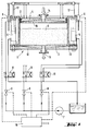
- FIG. 1 shows a cross section through a low-pressure chromatography column with associated control unit and circuit.
- Figure 2 shows a built-in pressure sensor and Figure 3 shows a built-in endoscope each in cross section.
- the low-pressure chromatography column 1 consists essentially of a vertical cylinder 13, a base plate 12 with outlet 15, a lower frit 3, which is arranged directly above the base plate 12, an upper frit 16, which is on the underside of a cover designed as a movable piston 4 is attached.
- the gap between piston 4 and cylinder 13 is sealed by a seal 2.
- the piston 4 is provided with an inlet 14.
- a package 9 preferably made of a gel, which is to be enclosed as homogeneously as possible, free of bubble-shaped cavities, between the two frits 16, 3.
- several, preferably three, hydraulic cylinders 5 are attached to the outside of the column, with the aid of which piston rods 17 can be moved vertically upwards or downwards via piston rods 17, which are connected to the piston 4, if necessary via a hydraulic unit 7 with controllable throttle valves 8 and reversing valves 11.
- a control unit 10 is used, to whose outputs the throttle valves 8 are connected.
- the inputs of the control unit 10 are electrically connected to signal transmitters 6, which are designed in particular as displacement transducers and one of which is attached to a piston rod 17 of the hydraulic cylinder 5.
- signal transmitters 6 which are designed in particular as displacement transducers and one of which is attached to a piston rod 17 of the hydraulic cylinder 5.
- Such a signal generator measures the vertical position of the piston rod 17 in question and reports it to the control unit 10 as an electrical signal.
- the entirety of the positions of the individual piston rods 17 characterize the vertical position and the horizontal position of the piston 4.
- control unit 10 actuates the hydraulic cylinders 5 via the throttle valves 8 in such a way that the piston 4 is guided horizontally and at a preselectable speed downwards.
- the piston can be moved upwards in a corresponding manner.
- the reversing valves 11 are actuated manually, an automation of this process is possible.
- the lower base plate 12 is designed as a movable piston instead of the upper one and is connected to elements 5 for raising or lowering the base plate 12.
- the plate and cover can also be designed to be movable.
- a pressure transducer 18 with a cylindrical pressure sensor 19 (FIG. 2) is installed in the piston 4, with the aid of which it is possible to measure the pressure directly above the gel material and to transmit it to the control unit 10.
- the inner diameter of the pressure sensor 19 ends flush with the surface of the frit 16.
- the cross-sectional area should be kept as small as possible in order not to unnecessarily reduce the area through which the frit 16 flows. It is also advantageous to equip the piston 4 with an observation device 20, preferably with an endoscope 21 (FIG. 3), since this has the advantage that the entire travel range of the piston 4 can be monitored.
- gel materials that can be used after the appropriate media "to breathe”. With these gel materials, the distance gel / frit underside can also be viewed or precisely adjusted.
- the piston 4 of the low-pressure chromatography column 1 is provided with a receptacle 22, which allows an endoscope 21 which is inserted below the frit 16 to be stretched through 360 ° and adjustable in height.
- the endoscope 21 with a 90 ° viewing angle makes it possible to set the exact distance between the gel material and the underside of the frit.
Landscapes
- Chemical & Material Sciences (AREA)
- Analytical Chemistry (AREA)
- General Health & Medical Sciences (AREA)
- Life Sciences & Earth Sciences (AREA)
- Health & Medical Sciences (AREA)
- Biochemistry (AREA)
- Physics & Mathematics (AREA)
- General Physics & Mathematics (AREA)
- Immunology (AREA)
- Pathology (AREA)
- Chemical Kinetics & Catalysis (AREA)
- Treatment Of Liquids With Adsorbents In General (AREA)
- Endoscopes (AREA)
Abstract
Description
- Die Erfindung betrifft eine Niederdruckchromatographiesäule mit einem Durchmesser größer als 30 cm.
Niederdruckchromatographiesäulen obengenannter Art sind bekannt. Sie bestehen im wesentlichen aus einem senkrecht stehenden Zylinder, einer Bodenplatte mit Auslauf, einer über der Bodenplatte angeordneten unteren Fritte, einer oberen Fritte und einem als beweglichen Kolben ausgebildeten Deckel mit Zulauf, wobei die obere Fritte an der Unterseite dieses Kolbens befestigt ist. - Derartige Niederdruckchromatographiesäulen für Drücke bis 10 bar werden u.a. in Verfahren zur Reinigung von Humaninsulin und dessen Vorstufen eingesetzt, wobei in einem von mehreren Verfahrensschritten die zu reinigende flüssige Phase durch den Zulauf in die Niederdruckchromatographiesäule einfließt, durch die obere Fritte dringt, auf den Weg nach unten durch eine Packung, die sich zwischen der unteren und der oberen Fritte befindet, gereinigt wird und dann durch die untere Fritte und den Auslauf die Niederdruckchromatographiesäule verläßt.
- Wichtig für einen guten Reinigungseffekt ist dabei, daß die Packung, die vorzugsweise aus einem Gelmaterial besteht, homogen, fest und möglichst frei von blasenförmigen Hohlräumen (z.B. Lufteinschlüsse) zwischen den Fritten eingeschlossen ist. Zur sachgemäßen Herstellung einer solchen Packung wird das Packungsmaterial in einer Flüssigkeit suspendiert und diese Suspension durch die oben offene Niederdruckchromatographiesäule auf die untere Fritte aufgegeben. Nach Absetzen des Gelmaterials wird der verfahrbare Kolben manuell unter Zuhilfenahme von Hebezeug oder Gewindestangen möglichst waagerecht in der Chromatographiesäule herabgelassen, bis die untere Fritte das Gelmaterial berührt. Sodann wird zusätzliche Flüssigkeit aufgegeben; dieser Flüssigkeitsstrom führt zu einer weiteren Verdichtung. Die Flüssigkeit wird unten abgesaugt bis die erwünschte Packungshöhe erreicht ist. Dieser Vorgang ist äußerst zeitraubend, arbeits- und personalintensiv, weil bei zunehmendem Säulendurchmesser, d.h. innerer Durchmesser des Zylinders ≧ 30 cm, die Führung des Kolbens immer schlechter wird (verkanten), was sich negativ auf das Packen und das Betreiben der Säule auswirkt.
- Zudem ist aus den Erfahrungen mit Hochdruckchromatographiesäulen bekannt, daß sich die Packung inhomogen ausbildet, wenn die vorstehend beschriebene Herstellung zu lange dauert. Die Folge ist ein schlechter Reinigungseffekt.
- Für diese Nachteile will die Erfindung Abhilfe schaffen.
- Erfindungsgemäß geschieht dies dadurch, daß die Niederdruckchromatographiesäule ansteuerbare Elemente zum Heben oder Senken des Kolbens aufweist, die mit dem Kolben verbunden sind, daß die ansteuerbaren Elemente mit Signalgebern zur Bestimmung von vertikaler Position und horizontaler Lage des Kolbens ausgerüstet sind und daß die Signalgeber mit einer Steuereinheit für die ansteuerbaren Elemente elektrisch verbunden sind.
- Weitere Ausgestaltungen der Erfindung ergeben sich aus den Ansprüchen 2 bis 7.
- Die Erfindung eignet sich zur Reinigung von Insulin und von dessen Vorstufen.
- Die mit ihr erzielbaren Vorteile äußern sich zum einen in einer einfachen und schnellen Herstellung der Packung, zum anderen zeigte sich überraschenderweise, daß mit einer solchen Packung reinere Produkte gewonnen werden können als bisher.
- Im folgenden wird ein Ausführungsbeispiel der Erfindung anhand der Zeichnung in den Figuren 1 bis 3 näher beschrieben.
- Die Figur 1 zeigt einen Querschnitt durch eine Niederdruckchromatographiesäule mit zugehöriger Steuereinheit und Verschaltung.
- Figur 2 zeigt einen eingebauten Druckaufnehmer und Figur 3 ein eingebautes Endoskop jeweils im Querschnitt.
- Die Niederdruckchromatographiesäule 1 besteht im wesentlichen aus einem senkrecht stehenden Zylinder 13, einer Bodenplatte 12 mit Ablauf 15, einer unteren Fritte 3, die direkt über der Bodenplatte 12 angeordnet ist, einer oberen Fritte 16, die an der Unterseite eines als beweglicher Kolben 4 ausgebildeten Deckels befestigt ist. Der Spalt zwischen Kolben 4 und Zylinder 13 wird durch eine Dichtung 2 abgedichtet. Der Kolben 4 ist mit einem Zulauf 14 versehen.
- Zwischen oberer Fritte 16 und unterer Fritte 3 befindet sich eine Packung 9, vorzugsweise aus einem Gel, die möglichst homogen, frei von blasenförmigen Hohlräumen fest zwischen den beiden Fritten 16, 3 eingeschlossen sein soll. Um dies in möglichst kurzer Zeit zu erreichen, sind außen an der Säule mehrere, vorzugsweise drei Hydraulikzylinder 5 angebracht, mit deren Hilfe über Kolbenstangen 17, die mit dem Kolben 4 verbunden sind, der Kolben 4 vertikal nach oben oder nach unten bewegt werden kann, gegebenenfalls über ein Hydraulikaggregat 7 mit ansteuerbaren Drosselventilen 8 und Umsteuerventilen 11.
- Zur Ansteuerung der Drosselventile 8 dient eine Steuereinheit 10, an deren Ausgänge die Drosselventile 8 angeschlossen sind.
- Die Eingänge der Steuereinheit 10 sind mit Signalgebern 6 elektrisch verbunden, die insbesondere als Wegaufnehmer ausgeführt sind und von denen jeweils einer an einer Kolbenstange 17 der Hydraulikzylinder 5 angebracht ist. Mit Hilfe solcher Signalgeber wird die vertikale Position der betreffenden Kolbenstange 17 gemessen und als elektrisches Signal an die Steuereinheit 10 gemeldet. Die Gesamtheit der Positionen der einzelnen Kolbenstangen 17 kennzeichnet die vertikale Position und die horizontale Lage des Kolbens 4.
- Je nach Position und Lage des Kolbens 4 betätigt die Steuereinheit 10 über die Drosselventile 8 die Hydraulikzylinder 5 in der Weise, daß der Kolben 4 waagrecht und mit einer vorwählbaren Geschwindigkeit nach unten geführt wird. Durch Betätigung der Umsteuerventile 11 kann der Kolben in entsprechender Weise nach oben geführt werden. Die Betätigung der Umsteuerventile 11 erfolgt manuell, eine Automatisierung dieses Vorgangs ist möglich.
- In einer weiteren Ausgestaltung der Erfindung ist anstelle der oberen die untere Bodenplatte 12 als ein beweglicher Kolben ausgebildet und mit Elementen 5 zum Heben oder Senken der Bodenplatte 12 verbunden.
- Selbstverständlich können auch Platte und Deckel beweglich ausgeführt sein.
- In einer besonderen Ausgestaltung ist in den Kolben 4 ein Druckaufnehmer 18 mit einem zylinderförmigen Drucksensor 19 (Fig. 2) eingebaut, mit dessen Hilfe es möglich ist, den Druck direkt über dem Gelmaterial zu messen und an die Steuereinheit 10 weiterzuleiten.
- Der innere Durchmesser des Drucksensors 19 endet bündig zur Oberfläche der Fritte 16. Die Querschnittsfläche sollte so klein wie möglich gehalten werden, um die durchströmte Fläche der Fritte 16 nicht unnötig zu verkleinern. Weiter ist es vorteilhaft, den Kolben 4 mit einer Beobachtungseinrichtung 20, vorzugsweise mit einem Endoskop 21 (Figur 3) auszurüsten, da dies den Vorteil hat, daß der gesamte Verfahrbereich des Kolbens 4 überwacht werden kann.
- Zudem gibt es Gelmaterialien, die nach Aufgabe entsprechender Medien "atmen". So läßt sich auch bei diesen Gelmaterialien der Abstand Gel/Frittenunterseite einsehen bzw. genau einstellen.
- Um eine Beobachtung zu ermöglichen, wird der Kolben 4 der Niedrdruckchromatographiesäule 1 mit einer Aufnahme 22 versehen, die es zuläßt, daß ein bis unter die Fritte 16 eingebrachtes Endoskop 21 um 360° dehnbar und in der Höhe verstellbar ist. Das Endoskop 21 mit 90° Blickwinkel ermöglicht es, den Abstand zwischen Gelmaterial und Frittenunterseite exakt einzustellen.
- Wichtig ist hierbei auch, daß durch die geringe Querschnittsfläche der Endoskopaufnahme der Aufgabefluß nicht übermäßig gestört wird.
Claims (8)
- Niederdruckchromatographiesäule (1) mit einem Durchmesser größer als 30 cm, im wesentlichen bestehend aus einem senkrecht stehenden Zylinder (13) mit einer Bodenplatte (12), einer unteren Fritte (3), die über der Bodenplatte (12) angeordnet ist, einer oberen Fritte (16), die an der Unterseite eines als beweglichen Kolben (4) ausgebildeten Deckels befestigt ist, dadurch gekennzeichnet,
daß die Niederdruckchromatographiesäule (1) ansteuerbare Elemente (5) zum Heben oder Senken des Kolbens (4) aufweist, die mit dem Kolben (4) verbunden sind,
daß die ansteuerbaren Elemente (5) mit Signalgebern (6) zur Bestimmung von vertikaler Position und horizontaler Lage des Kolbens (4) ausgerüstet sind und
daß die Signalgeber (6) mit einer Steuereinheit (10) für die ansteuerbaren Elemente (5) elektrisch verbunden sind. - Niederdruckchromatographiesäule gemäß Anspruch 1, dadurch gekennzeichnet, daß die Elemente (5) zum Heben oder Senken des Kolbens (4) Hydraulikzylinder sind.
- Niederdruckchromatographiesäule gemäß Anspruch 1, dadurch gekennzeichnet, daß die Elemente (5) zum Heben oder Senken des Kolbens (4) Pneumatikzylinder sind.
- Niederdruckchromatographiesäule nach Anspruch 1, dadurch gekennzeichnet, daß die Elemente (5) zum Heben oder Senken des Kolbens (4) elektromotorisch betreibbare Gewindespindeln sind.
- Niederdruckchromatographiesäule gemäß einem der Ansprüche 2 bis 4, dadurch gekennzeichnet, daß die Signalgeber (6) Wegaufnehmer sind.
- Niederdruckchromatographiesäule nach Anspruch 1, dadurch gekennzeichnet, daß die Niederdruckchromatographiesäule (1) mit einem Druckaufnehmer (18) zur Bestimmung des Druckes im Zylinder (13) ausgerüstet ist und daß dieser Druckaufnehmer (18) mit der Steuereinheit (10) elektrisch verbunden ist.
- Niederdruckchromatographiesäule nach Ansoruch 1, dadurch gekennzeichnet, daß der Kolben (4) mit einer Beobachtungseinrichtung (20) ausgerüstet ist.
- Verwendung einer Niederdruckchromatographiesäule nach Anspruch 1 zur Reinigung von Insulin oder dessen Vorstufen.
Applications Claiming Priority (2)
| Application Number | Priority Date | Filing Date | Title |
|---|---|---|---|
| DE4431662A DE4431662A1 (de) | 1994-09-06 | 1994-09-06 | Niederdruckchromatographiesäule mit automatisch bewegbarem Deckel |
| DE4431662 | 1994-09-06 |
Publications (2)
| Publication Number | Publication Date |
|---|---|
| EP0700706A1 true EP0700706A1 (de) | 1996-03-13 |
| EP0700706B1 EP0700706B1 (de) | 1999-03-03 |
Family
ID=6527506
Family Applications (1)
| Application Number | Title | Priority Date | Filing Date |
|---|---|---|---|
| EP95113295A Expired - Lifetime EP0700706B1 (de) | 1994-09-06 | 1995-08-24 | Niederdruckchromatographiesäule mit automatisch bewegbarem Deckel |
Country Status (7)
| Country | Link |
|---|---|
| US (1) | US5681474A (de) |
| EP (1) | EP0700706B1 (de) |
| JP (1) | JPH0894602A (de) |
| AT (1) | ATE177019T1 (de) |
| CA (1) | CA2157655A1 (de) |
| DE (2) | DE4431662A1 (de) |
| DK (1) | DK0700706T3 (de) |
Cited By (2)
| Publication number | Priority date | Publication date | Assignee | Title |
|---|---|---|---|---|
| EP2175268A1 (de) * | 2008-10-07 | 2010-04-14 | William H. Mann | Chromatographiesäulenverfahren mit Betrieb mit variabler Geschwindigkeit |
| EP4308263A4 (de) * | 2021-03-16 | 2024-09-25 | Bio-Rad Laboratories, Inc. | Dynamische axialkompression für präparative säulen mit externer kompression |
Families Citing this family (8)
| Publication number | Priority date | Publication date | Assignee | Title |
|---|---|---|---|---|
| US6824678B2 (en) * | 2003-02-06 | 2004-11-30 | Robert D. Thompson | Closure system for chromatography columns |
| GB0328674D0 (en) * | 2003-12-10 | 2004-01-14 | Euroflow Uk Ltd | Chromatography columns and their operation |
| US7402251B2 (en) * | 2005-12-28 | 2008-07-22 | Mann Welding Company | Chromatography column and method of operation |
| JP4973507B2 (ja) * | 2008-01-08 | 2012-07-11 | 栗田工業株式会社 | クロマトグラフィ装置およびクロマトグラフィ装置の制御装置 |
| JP2021105523A (ja) * | 2018-03-30 | 2021-07-26 | 株式会社カネカ | 脈動抑制により多糖類カラム担体が大型カラムに充填された充填ベッドの製造方法 |
| US11745119B2 (en) | 2018-04-16 | 2023-09-05 | Asahi Kasei Bioprocess America, Inc. | Chromatography and synthesis column apparatus and method of assembly |
| CN117015429A (zh) * | 2021-03-16 | 2023-11-07 | 生物辐射实验室股份有限公司 | 利用外部压缩对制备柱进行动态轴向压缩 |
| WO2024137514A1 (en) * | 2022-12-22 | 2024-06-27 | Synthego Corporation | Systems and method for automated oligonucleotide synthesis |
Citations (5)
| Publication number | Priority date | Publication date | Assignee | Title |
|---|---|---|---|---|
| DE1767790A1 (de) * | 1968-06-19 | 1971-07-01 | Heinrich Mack Fa | Verfahren und Vorrichtung zum Steuern grosstechnischer chromatographischer Saeulen |
| EP0008921A1 (de) * | 1978-09-08 | 1980-03-19 | Wright Scientific Limited | Verfahren und Vorrichtung zur Durchführung der Säulenchromatographie |
| EP0330503A2 (de) * | 1988-02-25 | 1989-08-30 | Tosoh Corporation | Verfahren für das Formen von einem Gelbett in einer Flüssigkeitschromatographiesäule und Vorrichtung mit einer Säule, die axial verstellbar ist, angewendet für dieses Verfahren |
| US4891133A (en) * | 1987-09-15 | 1990-01-02 | Cerex Corporation | Chromatography apparatus |
| US5324426A (en) * | 1992-03-20 | 1994-06-28 | Kontes Glass Corp. | Chromatography column |
Family Cites Families (3)
| Publication number | Priority date | Publication date | Assignee | Title |
|---|---|---|---|---|
| FR2219797B1 (de) * | 1973-03-01 | 1978-03-03 | Roussel Uclaf | |
| US5462659A (en) * | 1993-06-15 | 1995-10-31 | Sepragen Corporation | Chromatography column |
| US5450743A (en) * | 1994-01-10 | 1995-09-19 | Zymark Corporation | Method for providing constant flow in liquid chromatography system |
-
1994
- 1994-09-06 DE DE4431662A patent/DE4431662A1/de not_active Withdrawn
-
1995
- 1995-08-24 EP EP95113295A patent/EP0700706B1/de not_active Expired - Lifetime
- 1995-08-24 AT AT95113295T patent/ATE177019T1/de active
- 1995-08-24 DK DK95113295T patent/DK0700706T3/da active
- 1995-08-24 DE DE59505178T patent/DE59505178D1/de not_active Expired - Lifetime
- 1995-09-01 US US08/522,616 patent/US5681474A/en not_active Expired - Lifetime
- 1995-09-06 JP JP7228903A patent/JPH0894602A/ja active Pending
- 1995-09-06 CA CA002157655A patent/CA2157655A1/en not_active Abandoned
Patent Citations (5)
| Publication number | Priority date | Publication date | Assignee | Title |
|---|---|---|---|---|
| DE1767790A1 (de) * | 1968-06-19 | 1971-07-01 | Heinrich Mack Fa | Verfahren und Vorrichtung zum Steuern grosstechnischer chromatographischer Saeulen |
| EP0008921A1 (de) * | 1978-09-08 | 1980-03-19 | Wright Scientific Limited | Verfahren und Vorrichtung zur Durchführung der Säulenchromatographie |
| US4891133A (en) * | 1987-09-15 | 1990-01-02 | Cerex Corporation | Chromatography apparatus |
| EP0330503A2 (de) * | 1988-02-25 | 1989-08-30 | Tosoh Corporation | Verfahren für das Formen von einem Gelbett in einer Flüssigkeitschromatographiesäule und Vorrichtung mit einer Säule, die axial verstellbar ist, angewendet für dieses Verfahren |
| US5324426A (en) * | 1992-03-20 | 1994-06-28 | Kontes Glass Corp. | Chromatography column |
Cited By (3)
| Publication number | Priority date | Publication date | Assignee | Title |
|---|---|---|---|---|
| EP2175268A1 (de) * | 2008-10-07 | 2010-04-14 | William H. Mann | Chromatographiesäulenverfahren mit Betrieb mit variabler Geschwindigkeit |
| EP4308263A4 (de) * | 2021-03-16 | 2024-09-25 | Bio-Rad Laboratories, Inc. | Dynamische axialkompression für präparative säulen mit externer kompression |
| US12345688B2 (en) | 2021-03-16 | 2025-07-01 | Bio-Rad Laboratories, Inc. | Dynamic axial compression for preparative columns using external compression |
Also Published As
| Publication number | Publication date |
|---|---|
| JPH0894602A (ja) | 1996-04-12 |
| DK0700706T3 (da) | 1999-10-04 |
| DE4431662A1 (de) | 1996-03-07 |
| ATE177019T1 (de) | 1999-03-15 |
| DE59505178D1 (de) | 1999-04-08 |
| US5681474A (en) | 1997-10-28 |
| EP0700706B1 (de) | 1999-03-03 |
| CA2157655A1 (en) | 1996-03-07 |
Similar Documents
| Publication | Publication Date | Title |
|---|---|---|
| DE2409935C2 (de) | ||
| EP0700706B1 (de) | Niederdruckchromatographiesäule mit automatisch bewegbarem Deckel | |
| DE2627160C3 (de) | Verfahren zum Herstellen von Tellern o.dgl. mittels einer Presse sowie Presse zur Durchführung des Verfahrens | |
| DE3920097C2 (de) | Vorrichtung zur Filtration von mit Partikeln belasteten Flüssigkeiten | |
| DE2324839A1 (de) | Pressvorrichtung | |
| DE19643859A1 (de) | Anzeigevorrichtung für den Staubbehälter eines Staubsaugers | |
| EP0123792B1 (de) | Funkenerosionsmaschine | |
| DE102015101169A1 (de) | Schleifstaub-Absaugvorrichtung | |
| EP0060346B1 (de) | Druckfiltrationsgerät | |
| DE10247624A1 (de) | Matratze | |
| DE3306362A1 (de) | Druck-band-filter, insbesondere zur entwaesserung von feinkohle | |
| DE2153544C3 (de) | Vorrichtung zum Abfräsen von Straßendecken | |
| DE484963C (de) | Dreh-Planfilter | |
| DE2915415C2 (de) | Elektrophoresegerät | |
| DE7223508U (de) | Kantenschleifmaschine | |
| DE202015005240U1 (de) | Chromatographiesäulen und ihre Bedienung | |
| DE2401472C3 (de) | Vorrichtung zum Abfüllen von fließfähigem, körnigem Gut aus einem Vorratsbehälter in Hohlraumprofile mit geringem Querschnitt | |
| DE1933056C (de) | Vorrichtung zur stufenlosen Einstellung des Rucklaufverhaltnisses einer Destinations kolonne | |
| AT360692B (de) | Vorrichtung zum kontinuierlichen durchlaufver- pressen von isolierglas, zwei- oder mehrscheibenglas od.dgl. | |
| DE821724C (de) | Kaesepresse | |
| DE4211500C2 (de) | Drehtischpresse für Betonplatten o. dgl. | |
| EP0088882A2 (de) | Druck-Band-Filter, insbesondere zur Entwässerung von Feinkohle | |
| DE2902360A1 (de) | Fuellanzeigesystem fuer pressbehaelter | |
| DE19525856C2 (de) | Chromatographische Säule | |
| DE1536851C (de) | Abdichtung eines verschiebbaren Filterbandes in einer Filtervorrichtung |
Legal Events
| Date | Code | Title | Description |
|---|---|---|---|
| PUAI | Public reference made under article 153(3) epc to a published international application that has entered the european phase |
Free format text: ORIGINAL CODE: 0009012 |
|
| AK | Designated contracting states |
Kind code of ref document: A1 Designated state(s): AT BE CH DE DK FR GB IE IT LI NL SE |
|
| 17P | Request for examination filed |
Effective date: 19960913 |
|
| 17Q | First examination report despatched |
Effective date: 19971204 |
|
| GRAG | Despatch of communication of intention to grant |
Free format text: ORIGINAL CODE: EPIDOS AGRA |
|
| GRAG | Despatch of communication of intention to grant |
Free format text: ORIGINAL CODE: EPIDOS AGRA |
|
| GRAH | Despatch of communication of intention to grant a patent |
Free format text: ORIGINAL CODE: EPIDOS IGRA |
|
| GRAH | Despatch of communication of intention to grant a patent |
Free format text: ORIGINAL CODE: EPIDOS IGRA |
|
| GRAA | (expected) grant |
Free format text: ORIGINAL CODE: 0009210 |
|
| AK | Designated contracting states |
Kind code of ref document: B1 Designated state(s): AT BE CH DE DK FR GB IE IT LI NL SE |
|
| REF | Corresponds to: |
Ref document number: 177019 Country of ref document: AT Date of ref document: 19990315 Kind code of ref document: T |
|
| REG | Reference to a national code |
Ref country code: CH Ref legal event code: EP |
|
| REG | Reference to a national code |
Ref country code: IE Ref legal event code: FG4D Free format text: GERMAN |
|
| ET | Fr: translation filed | ||
| REF | Corresponds to: |
Ref document number: 59505178 Country of ref document: DE Date of ref document: 19990408 |
|
| ITF | It: translation for a ep patent filed | ||
| GBT | Gb: translation of ep patent filed (gb section 77(6)(a)/1977) |
Effective date: 19990506 |
|
| REG | Reference to a national code |
Ref country code: DK Ref legal event code: T3 |
|
| PLBE | No opposition filed within time limit |
Free format text: ORIGINAL CODE: 0009261 |
|
| STAA | Information on the status of an ep patent application or granted ep patent |
Free format text: STATUS: NO OPPOSITION FILED WITHIN TIME LIMIT |
|
| 26N | No opposition filed | ||
| REG | Reference to a national code |
Ref country code: GB Ref legal event code: IF02 |
|
| PGFP | Annual fee paid to national office [announced via postgrant information from national office to epo] |
Ref country code: IE Payment date: 20140812 Year of fee payment: 20 Ref country code: DE Payment date: 20140821 Year of fee payment: 20 Ref country code: NL Payment date: 20140809 Year of fee payment: 20 Ref country code: DK Payment date: 20140812 Year of fee payment: 20 Ref country code: CH Payment date: 20140812 Year of fee payment: 20 |
|
| PGFP | Annual fee paid to national office [announced via postgrant information from national office to epo] |
Ref country code: SE Payment date: 20140826 Year of fee payment: 20 Ref country code: GB Payment date: 20140820 Year of fee payment: 20 Ref country code: AT Payment date: 20140626 Year of fee payment: 20 Ref country code: FR Payment date: 20140808 Year of fee payment: 20 |
|
| PGFP | Annual fee paid to national office [announced via postgrant information from national office to epo] |
Ref country code: IT Payment date: 20140822 Year of fee payment: 20 |
|
| PGFP | Annual fee paid to national office [announced via postgrant information from national office to epo] |
Ref country code: BE Payment date: 20140812 Year of fee payment: 20 |
|
| REG | Reference to a national code |
Ref country code: DE Ref legal event code: R071 Ref document number: 59505178 Country of ref document: DE |
|
| REG | Reference to a national code |
Ref country code: DK Ref legal event code: EUP Effective date: 20150824 |
|
| REG | Reference to a national code |
Ref country code: NL Ref legal event code: V4 Effective date: 20150824 |
|
| REG | Reference to a national code |
Ref country code: CH Ref legal event code: PL |
|
| REG | Reference to a national code |
Ref country code: GB Ref legal event code: PE20 Expiry date: 20150823 |
|
| REG | Reference to a national code |
Ref country code: IE Ref legal event code: MK9A |
|
| REG | Reference to a national code |
Ref country code: SE Ref legal event code: EUG |
|
| REG | Reference to a national code |
Ref country code: AT Ref legal event code: MK07 Ref document number: 177019 Country of ref document: AT Kind code of ref document: T Effective date: 20150824 |
|
| PG25 | Lapsed in a contracting state [announced via postgrant information from national office to epo] |
Ref country code: IE Free format text: LAPSE BECAUSE OF EXPIRATION OF PROTECTION Effective date: 20150824 Ref country code: GB Free format text: LAPSE BECAUSE OF EXPIRATION OF PROTECTION Effective date: 20150823 |