EP0700728A1 - Horizontaler Zyklonseparator für einen Wirbelbettreaktor - Google Patents
Horizontaler Zyklonseparator für einen Wirbelbettreaktor Download PDFInfo
- Publication number
- EP0700728A1 EP0700728A1 EP95305298A EP95305298A EP0700728A1 EP 0700728 A1 EP0700728 A1 EP 0700728A1 EP 95305298 A EP95305298 A EP 95305298A EP 95305298 A EP95305298 A EP 95305298A EP 0700728 A1 EP0700728 A1 EP 0700728A1
- Authority
- EP
- European Patent Office
- Prior art keywords
- cyclone separator
- vortex chamber
- solids
- chamber
- separated
- Prior art date
- Legal status (The legal status is an assumption and is not a legal conclusion. Google has not performed a legal analysis and makes no representation as to the accuracy of the status listed.)
- Granted
Links
- 239000007787 solid Substances 0.000 claims abstract description 36
- 239000007789 gas Substances 0.000 claims abstract description 30
- 239000000203 mixture Substances 0.000 claims abstract description 13
- 238000005192 partition Methods 0.000 claims description 16
- 239000002245 particle Substances 0.000 claims description 14
- 238000004891 communication Methods 0.000 claims description 2
- 238000007599 discharging Methods 0.000 claims description 2
- 238000002485 combustion reaction Methods 0.000 abstract description 4
- 239000000446 fuel Substances 0.000 description 9
- 239000012530 fluid Substances 0.000 description 6
- 239000000463 material Substances 0.000 description 6
- XLYOFNOQVPJJNP-UHFFFAOYSA-N water Substances O XLYOFNOQVPJJNP-UHFFFAOYSA-N 0.000 description 6
- 239000010419 fine particle Substances 0.000 description 2
- 230000005484 gravity Effects 0.000 description 2
- 238000000926 separation method Methods 0.000 description 2
- 235000019738 Limestone Nutrition 0.000 description 1
- 230000001133 acceleration Effects 0.000 description 1
- 239000003463 adsorbent Substances 0.000 description 1
- 239000003245 coal Substances 0.000 description 1
- 239000000567 combustion gas Substances 0.000 description 1
- 150000001875 compounds Chemical class 0.000 description 1
- 238000001816 cooling Methods 0.000 description 1
- 239000010459 dolomite Substances 0.000 description 1
- 229910000514 dolomite Inorganic materials 0.000 description 1
- 239000006028 limestone Substances 0.000 description 1
- 238000011084 recovery Methods 0.000 description 1
- 238000004064 recycling Methods 0.000 description 1
- 230000001105 regulatory effect Effects 0.000 description 1
- 238000007789 sealing Methods 0.000 description 1
- 239000002594 sorbent Substances 0.000 description 1
- 239000002915 spent fuel radioactive waste Substances 0.000 description 1
- 238000007382 vortex spinning Methods 0.000 description 1
Images

Classifications
-
- F—MECHANICAL ENGINEERING; LIGHTING; HEATING; WEAPONS; BLASTING
- F23—COMBUSTION APPARATUS; COMBUSTION PROCESSES
- F23C—METHODS OR APPARATUS FOR COMBUSTION USING FLUID FUEL OR SOLID FUEL SUSPENDED IN A CARRIER GAS OR AIR
- F23C10/00—Fluidised bed combustion apparatus
- F23C10/02—Fluidised bed combustion apparatus with means specially adapted for achieving or promoting a circulating movement of particles within the bed or for a recirculation of particles entrained from the bed
- F23C10/04—Fluidised bed combustion apparatus with means specially adapted for achieving or promoting a circulating movement of particles within the bed or for a recirculation of particles entrained from the bed the particles being circulated to a section, e.g. a heat-exchange section or a return duct, at least partially shielded from the combustion zone, before being reintroduced into the combustion zone
- F23C10/08—Fluidised bed combustion apparatus with means specially adapted for achieving or promoting a circulating movement of particles within the bed or for a recirculation of particles entrained from the bed the particles being circulated to a section, e.g. a heat-exchange section or a return duct, at least partially shielded from the combustion zone, before being reintroduced into the combustion zone characterised by the arrangement of separation apparatus, e.g. cyclones, for separating particles from the flue gases
- F23C10/10—Fluidised bed combustion apparatus with means specially adapted for achieving or promoting a circulating movement of particles within the bed or for a recirculation of particles entrained from the bed the particles being circulated to a section, e.g. a heat-exchange section or a return duct, at least partially shielded from the combustion zone, before being reintroduced into the combustion zone characterised by the arrangement of separation apparatus, e.g. cyclones, for separating particles from the flue gases the separation apparatus being located outside the combustion chamber
-
- B—PERFORMING OPERATIONS; TRANSPORTING
- B04—CENTRIFUGAL APPARATUS OR MACHINES FOR CARRYING-OUT PHYSICAL OR CHEMICAL PROCESSES
- B04C—APPARATUS USING FREE VORTEX FLOW, e.g. CYCLONES
- B04C5/00—Apparatus in which the axial direction of the vortex is reversed
- B04C5/08—Vortex chamber constructions
- B04C5/103—Bodies or members, e.g. bulkheads, guides, in the vortex chamber
-
- B—PERFORMING OPERATIONS; TRANSPORTING
- B04—CENTRIFUGAL APPARATUS OR MACHINES FOR CARRYING-OUT PHYSICAL OR CHEMICAL PROCESSES
- B04C—APPARATUS USING FREE VORTEX FLOW, e.g. CYCLONES
- B04C5/00—Apparatus in which the axial direction of the vortex is reversed
- B04C5/14—Construction of the underflow ducting; Apex constructions; Discharge arrangements ; discharge through sidewall provided with a few slits or perforations
-
- B—PERFORMING OPERATIONS; TRANSPORTING
- B04—CENTRIFUGAL APPARATUS OR MACHINES FOR CARRYING-OUT PHYSICAL OR CHEMICAL PROCESSES
- B04C—APPARATUS USING FREE VORTEX FLOW, e.g. CYCLONES
- B04C5/00—Apparatus in which the axial direction of the vortex is reversed
- B04C5/20—Apparatus in which the axial direction of the vortex is reversed with heating or cooling, e.g. quenching, means
-
- B—PERFORMING OPERATIONS; TRANSPORTING
- B04—CENTRIFUGAL APPARATUS OR MACHINES FOR CARRYING-OUT PHYSICAL OR CHEMICAL PROCESSES
- B04C—APPARATUS USING FREE VORTEX FLOW, e.g. CYCLONES
- B04C9/00—Combinations with other devices, e.g. fans, expansion chambers, diffusors, water locks
-
- F—MECHANICAL ENGINEERING; LIGHTING; HEATING; WEAPONS; BLASTING
- F23—COMBUSTION APPARATUS; COMBUSTION PROCESSES
- F23J—REMOVAL OR TREATMENT OF COMBUSTION PRODUCTS OR COMBUSTION RESIDUES; FLUES
- F23J2900/00—Special arrangements for conducting or purifying combustion fumes; Treatment of fumes or ashes
- F23J2900/15026—Cyclone separators with horizontal axis
Definitions
- This invention relates in general to a cyclone separator, and, more particularly, to a horizontal cyclone separator for separating solid particles from gases generated by the combustion of fuel in a fluidized bed reactor, or the like.
- a typical cyclone separator is usually associated with a fluidized bed reactor and includes a vertically-oriented, cylindrical vortex chamber in which is disposed a central gas outlet pipe for carrying the separated gases upwardly, while the separated solids are returned to the fluidized bed through a funnel-shaped base of the separator via a standpipe.
- These vertical cyclone separators are substantial in size and eliminate the possibility of a compact system design which can be modularized and easily transported and erected.
- several vertical cyclone separators are often required to provide adequate particle separation, which compound the size problem and, in addition, usually require complicated gas duct arrangements with reduced operating efficiency.
- Horizontal cyclone separators characterized by a horizontally-oriented, cylindrical vortex chamber have been constructed which eliminate many of the above mentioned problems.
- horizontal cyclone separators may be readily configured within the upper portion of the reactor and integrated with the walls of the reactor making the bulk, weight, and cost much less than conventional separators. Additionally, they can be modularized making them easy to erect.
- many known horizontal cyclone separators have various shortcomings, particularly with regard to their gas-solids inlet which extends substantially the full length of the separator. This extended length causes the separated solids that have collected on the wall past the exit to become re-entrained in the incoming gas-solids stream.
- Another shortcoming is that the vertical end wall opposite the gas outlet causes the separated solids to bounce off the latter wall and become re-entrained in the separated gas stream.
- the horizontal cyclone separator of the present invention includes a furnace section and a vortex chamber communicating with the furnace section and having an inlet which extends a fraction of the length of the furnace section and receives a mixture of the gaseous products of combustion and solids entrained by the gases. Once inside the vortex chamber, the solids are separated from the mixture by centrifugal action.
- a coaxially disposed tube extends partially into the chamber to allow the separated gases to exit the separator.
- a ring-shaped solids deflector is disposed on the vertical wall opposite the coaxially disposed tube to prevent solids from bouncing off the rear wall towards the center of the separator and into the path of the separated gas stream. The separated solids fall into a trough formed in a lower portion of the furnace section for returning the solids back to the furnace section.
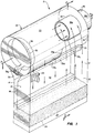
- the reference numeral 10 refers, in general, to the fluidized bed reactor of the present invention.
- the reactor 10 includes a front wall 12, a spaced parallel rear wall 14, and an intermediate partition 16 extending between the walls 12 and 14 in a spaced, parallel relation thereto.
- first and second sidewalls 18 and 20 extend perpendicular to the front wall 12 and the rear wall 14 to form a substantially rectangular vessel.
- the upper portions 12a and 14a of the walls 12 and 14, respectively, are curved and extend towards each other to provide a roof for the vessel.
- the front wall 12 and the partition 16, along with corresponding portions of the sidewalls 18 and 20, form a furnace section 22.
- the walls 12 and 14, the partition 16, and the sidewalls 18 and 20 are each formed by a plurality of vertically-disposed tubes 23 (FIG. 1) interconnected by vertically-disposed elongated bars, or fins to form a contiguous, airtight structure. Since this type of structure is conventional, it will not be described in further detail.
- headers are connected to the upper and lower ends of the walls 12 and 14 for introducing fluid to, and receiving fluid from, the tubes 23 forming the respective walls.
- Downcomers connect a steam drum (not shown) to the headers by branch conduits for passing fluid from the drum to the headers.
- Conduits (not shown) connect the upper headers to the steam drum for returning fluid from the headers to the drum.
- the aforementioned flow circuitry is also provided for the partition 16 and the sidewalls 18 and 20, and it is understood that the reactor 10 may be equipped with additional flow circuitry for improving the transfer of heat from the reactor 10. Since, this type of flow circuitry is well known, it is not shown in the drawings nor will it be described in further detail.
- a perforated air distribution plate 24 is suitably supported at a lower portion of the furnace section 22 and defines a plenum chamber 26 extending below the plate 24.
- Air from a suitable source is introduced into the plenum chamber 26 by conventional means, such as a forced-draft blower, or the like.
- the air introduced through the plenum chamber 26 passes in an upwardly direction through the air distribution plate 24 and may be preheated by air preheaters and appropriately regulated by air control dampers as needed.
- the air distribution plate 26 is adapted to support a bed of particulate fuel material consisting, in general, of crushed coal and limestone, or dolomite.
- a fuel distributor pipe 27 (FIGS. 2 and 4) extends through the front wall 12 for introducing the particulate fuel into the furnace section 22, it being understood that other pipes can be associated with the walls 12, 18, and 20 for distributing particulate fuel material and/or additional particulate fuel material into the furnace section as needed. It is understood that a drain pipe may register with an opening in the air distribution plate 24 and extend through the plenum 26 for discharging spent fuel and sorbent material from the furnace section 22 to external equipment.
- a horizontal cyclone separator designated generally by the reference numeral 28, is provided in an upper portion of the vessel formed by the reactor 10.
- the separator 28 includes a horizontally-disposed vortex chamber 30 for separating solid particles from a mixture of gases and particles, in a manner to be described.
- the vortex chamber 30 is generally cylindrical and is defined by the upper, curved portions 12a and 14a of the front wall 12 and the rear wall 14, respectively, as well as an upper portion 16a of the partition 16 which is curved towards, and is connected to, the curved wall portion 12a.
- An elongated opening formed in the upper portion 16a of the partition 16 defines an inlet 32 extending a fraction of the length of the furnace section 22 and the vortex chamber 30.
- the vertical portions of the partition 16 and the wall 14 define an outlet trough 34 extending from a lower portion of the vortex chamber 30 to an area just above the distribution plate 24.
- the wall 14 and the partition 16 also include angularly extending straight portions 14b and 16b, respectively, which define a horizontally oriented funnel 35, extending the full length of the vortex chamber 30, for directing the separated solids from the vortex chamber 30 to the outlet trough 34.
- a solid block 33 having ends 33a and 33b (FIG.1); sides 33c and 33d; a top 33e; and a bottom 33f is disposed in the furnace section 22 and is mounted on the partition 16, with the side 33d and the top 33e of the block engaging the wall portions 16b and 16a, respectively, of the partition 16 as shown in FIGS. 2 and 4.
- the side 33c of the block 33 is positioned just below the inlet 32 and parallel to the wall 12 to define, along with the latter wall and the sidewall 20, a straight passage, having a substantially rectangular cross-section, registering with the inlet 32 to direct the flow of entrained solids and gases substantially tangential into the separator 28.
- a central open-ended tube 36 extends through the sidewall 20 and has a first portion 36a extending just above the inlet 32 as viewed in FIG. 1, and a second portion 36b projecting outwardly from the latter wall.
- a generally ring-shaped solids deflector 38 having an outer annular flange 39 extends inwardly from wall 18 and is connected to the wall in any conventional manner.
- An opening, or slot, 38a is defined in the lower portion of the deflector 38 for directing separated solids into the funnel 35 and the outlet trough 34.
- particulate fuel material is introduced to the air distribution plate 24 from the distributor pipe 27 and is ignited by a light-off burner (not shown), or the like.
- Additional material such as adsorbent material, or the like, may be introduced through other distributors into the interior of the furnace section 22, if needed.
- a high-pressure, high-velocity, combustion supporting air is introduced through the air distribution plate 24 from the plenum chamber 26 at a velocity which is greater than the free-fall velocity of the relatively fine particles in the bed and less than the free-fall velocity of relatively course particles.
- a portion of the fine particles become entrained and pneumatically transported by air and the combustion gases.
- the mixture of entrained particles and gases rises upwardly within the furnace section 22 and is directed by the block 33 and corresponding portions of the walls 12 and 20 through the inlet 32 and into the vortex chamber 30 in a direction substantially tangential to the vortex chamber 30 and thus swirls around in the chamber.
- the entrained solid particles are propelled by centrifugal forces against the inner surfaces of the upper portions 12a, 14a, and 16a of the walls 12 and 14 and the partition 16, respectively, forming the vortex chamber 30, where they collect and are thus separated from the gases.
- the separated particles then fall downwardly by gravity into the funnel 35 and the outlet trough 34.
- the partition 16 extends sufficiently into the fuel bed supported by the distribution plate 24 so that the particles can flow from the outlet trough 34 into the furnace section 22 as needed, while sealing against backflow of the high-pressure gases from the furnace section 22.
- the pressure changes created by the spiral flow force the separated gases concentrating along the central axis of the vortex chamber 30 toward the low pressure area created at the inlet opening of the tube 36.
- the clean gases thus pass into the tube 36 and exit through the outlet opening directly into a heat recovery section or other external equipment.
- Water is introduced into the system through water feed pipes that are conducted downwardly through the tubes forming the walls 12, 14, 18, and 20 and the partition 16 as described above.
- Heat from the fluidized bed, the gas column, and the transported solids convert a portion of the water into steam, and the mixture of water and steam rises in the tubes, collects in a set of upper headers and is transferred to a steam drum.
- the steam and water are separated within the steam drum in a conventional manner and passed to conventional external equipment.
- Other cooling surfaces preferably in the form of partition walls with essentially vertical tubes, can be utilized in the furnace section 22.
- the reactor of the present invention provides several advantages.
- the provision of the horizontal cyclone separator integrated in the upper portion of the reactor 10, with the outlet trough 34 connected directly to the fuel bed of the furnace section 22, permits the separation of the entrained particles and the recycling of same back to the furnace section while eliminating the need for relatively bulky and expensive vertical cyclone separators.
- the gas-solids mixture enters the vortex chamber 30 generally tangentially through the inlet 32 extending along a fraction of the length of the furnace section, without being significantly redirected by unnecessary baffles, tubes and/or ducting.
- the inlet 32 extends only a fraction of the length of the separator 28 thereby preventing separated solids within the vortex chamber 30 from encountering the incoming gas-solids mixture.
- the ring-shaped solids deflector 38 prevents solids from bouncing from the rear wall 18 into the exiting gas vortex spinning towards the gas exit 42.
- the central tube 36 promotes well-defined circulation in the vortex chamber 30, thereby providing sufficient centrifugal force to counteract the reversal of acceleration caused by the earth's gravity.
- the outer portion 36b of the tube 36 is provided just behind the end of the vortex chamber 30, the hot, clean gases are transferred directly and quickly into external equipment without the need for additional piping and intricate duct arrangements.
- the walls of the vessel of the reactor 10 may be reconfigured to accommodate more than one horizontal cyclone separator in the upper portion thereof in communication with the furnace section.
- the headers and flow circuitry have been described, it should be understood that any other suitable header and flow circuitry arrangement could be employed in connection with the present invention.
Landscapes
- Engineering & Computer Science (AREA)
- Chemical & Material Sciences (AREA)
- Combustion & Propulsion (AREA)
- Mechanical Engineering (AREA)
- General Engineering & Computer Science (AREA)
- Fluidized-Bed Combustion And Resonant Combustion (AREA)
- Cyclones (AREA)
- Devices And Processes Conducted In The Presence Of Fluids And Solid Particles (AREA)
- Incineration Of Waste (AREA)
- Separating Particles In Gases By Inertia (AREA)
- Waste-Gas Treatment And Other Accessory Devices For Furnaces (AREA)
Applications Claiming Priority (2)
| Application Number | Priority Date | Filing Date | Title |
|---|---|---|---|
| US08/288,864 US6245300B1 (en) | 1994-08-11 | 1994-08-11 | Horizontal cyclone separator for a fluidized bed reactor |
| US288864 | 1994-08-11 |
Publications (2)
| Publication Number | Publication Date |
|---|---|
| EP0700728A1 true EP0700728A1 (de) | 1996-03-13 |
| EP0700728B1 EP0700728B1 (de) | 1999-04-28 |
Family
ID=23109011
Family Applications (1)
| Application Number | Title | Priority Date | Filing Date |
|---|---|---|---|
| EP95305298A Expired - Lifetime EP0700728B1 (de) | 1994-08-11 | 1995-07-28 | Wirbelbettreaktor |
Country Status (6)
| Country | Link |
|---|---|
| US (1) | US6245300B1 (de) |
| EP (1) | EP0700728B1 (de) |
| JP (1) | JP2829839B2 (de) |
| CA (1) | CA2153866A1 (de) |
| DE (1) | DE69509326T2 (de) |
| ES (1) | ES2131770T3 (de) |
Cited By (5)
| Publication number | Priority date | Publication date | Assignee | Title |
|---|---|---|---|---|
| WO1998022199A1 (en) * | 1996-11-19 | 1998-05-28 | Foster Wheeler Energia Oy | An apparatus and a method for separating particles from hot gases |
| CN101666493B (zh) * | 2009-08-28 | 2011-05-11 | 无锡海源重工股份有限公司 | 一种工业循环流化床锅炉的卧式旋风分离器 |
| CN101514811B (zh) * | 2009-03-17 | 2011-12-07 | 西安交通大学 | 无夹廊角管全膜式壁循环流化床锅炉 |
| CN103398375A (zh) * | 2013-07-01 | 2013-11-20 | 中国华能集团清洁能源技术研究院有限公司 | 带有耐磨靶区及导向装置的循环流化床锅炉旋风分离器 |
| CN111632559A (zh) * | 2020-07-03 | 2020-09-08 | 北京蓝鼎科创装备科技有限公司 | 一种流化床 |
Families Citing this family (6)
| Publication number | Priority date | Publication date | Assignee | Title |
|---|---|---|---|---|
| US8703063B2 (en) * | 2010-06-21 | 2014-04-22 | Chevron Phillips Chemical Company Lp | System and method for closed relief of a polyolefin loop reactor system |
| AT512151B1 (de) * | 2012-05-24 | 2013-06-15 | A Tec Holding Gmbh | Vorrichtung zum Abtrennen von Stoffen aus einem Medium |
| CN102759095B (zh) * | 2012-07-27 | 2016-03-02 | 哈尔滨锅炉厂有限责任公司 | 亚临界300mw锅炉水冷壁上升管及引出方法 |
| US9865852B2 (en) | 2015-06-25 | 2018-01-09 | Tesla, Inc. | Energy storage container with vortex separator |
| CN106622699B (zh) * | 2016-12-14 | 2018-11-13 | 扬州科润德机械有限公司 | 一种卧式旋风分离装置 |
| CN107344039A (zh) * | 2017-08-22 | 2017-11-14 | 浙江科技学院 | 一种连接下行床的气固分离系统 |
Citations (3)
| Publication number | Priority date | Publication date | Assignee | Title |
|---|---|---|---|---|
| DE845147C (de) * | 1951-02-17 | 1952-07-28 | Walther & Cie Ag | Einrichtung bei zylindrischen Fliehkraft-Abscheidezellen zur Beeinflussung der Wirbelachse |
| EP0250046A2 (de) * | 1986-06-16 | 1987-12-23 | Shell Internationale Researchmaatschappij B.V. | Horizontaler Zyklonseparator |
| US5174799A (en) | 1990-04-06 | 1992-12-29 | Foster Wheeler Energy Corporation | Horizontal cyclone separator for a fluidized bed reactor |
Family Cites Families (13)
| Publication number | Priority date | Publication date | Assignee | Title |
|---|---|---|---|---|
| US2888096A (en) * | 1955-06-22 | 1959-05-26 | Shell Dev | Horizontal centrifugal separator |
| JPS562863A (en) * | 1979-06-18 | 1981-01-13 | Kawasaki Heavy Ind Ltd | Dust collector |
| US4285142A (en) * | 1979-08-27 | 1981-08-25 | Kawasaki Jukogyo Kabushiki Kaisha | Suspension type heat exchanger |
| US5171542A (en) * | 1984-03-20 | 1992-12-15 | A. Ahlstrom Corporation | Circulating fluidized bed reactor |
| DE3414344C2 (de) * | 1984-04-16 | 1987-01-15 | Gebrüder Bühler AG, Uzwil | Fliehkraftabscheider |
| FI842202A0 (fi) | 1984-06-01 | 1984-06-01 | Ahlstroem Oy | Anordning foer avskiljning av fast material i reaktor med cirkulerande baedd. |
| US4900516A (en) * | 1984-06-01 | 1990-02-13 | A. Ahlstrom Corporation | Fluidized bed reactor |
| US4732113A (en) | 1987-03-09 | 1988-03-22 | A. Ahlstrom Corporation | Particle separator |
| GB8805755D0 (en) * | 1988-03-10 | 1988-04-07 | Shell Int Research | Apparatus for separation of solids from mixture of solids & fluid |
| US5207805A (en) * | 1991-01-11 | 1993-05-04 | Emtrol Corporation | Cyclone separator system |
| BR9102123A (pt) * | 1991-05-24 | 1992-04-28 | Serrana Sa De Mineracao | Ciclone separador de po tipo single loop |
| US5226936A (en) * | 1991-11-21 | 1993-07-13 | Foster Wheeler Energy Corporation | Water-cooled cyclone separator |
| US5362379A (en) * | 1991-12-27 | 1994-11-08 | Amoco Corporation | Open-bottomed cyclone with gas inlet tube and method |
-
1994
- 1994-08-11 US US08/288,864 patent/US6245300B1/en not_active Expired - Fee Related
-
1995
- 1995-07-13 CA CA002153866A patent/CA2153866A1/en not_active Abandoned
- 1995-07-28 DE DE69509326T patent/DE69509326T2/de not_active Expired - Fee Related
- 1995-07-28 ES ES95305298T patent/ES2131770T3/es not_active Expired - Lifetime
- 1995-07-28 EP EP95305298A patent/EP0700728B1/de not_active Expired - Lifetime
- 1995-08-09 JP JP7203089A patent/JP2829839B2/ja not_active Expired - Lifetime
Patent Citations (4)
| Publication number | Priority date | Publication date | Assignee | Title |
|---|---|---|---|---|
| DE845147C (de) * | 1951-02-17 | 1952-07-28 | Walther & Cie Ag | Einrichtung bei zylindrischen Fliehkraft-Abscheidezellen zur Beeinflussung der Wirbelachse |
| EP0250046A2 (de) * | 1986-06-16 | 1987-12-23 | Shell Internationale Researchmaatschappij B.V. | Horizontaler Zyklonseparator |
| US5174799A (en) | 1990-04-06 | 1992-12-29 | Foster Wheeler Energy Corporation | Horizontal cyclone separator for a fluidized bed reactor |
| EP0592737A1 (de) * | 1990-04-06 | 1994-04-20 | Foster Wheeler Energy Corporation | Horizontaler Zyklonseparator für einen Wirbelbettreaktor |
Cited By (6)
| Publication number | Priority date | Publication date | Assignee | Title |
|---|---|---|---|---|
| WO1998022199A1 (en) * | 1996-11-19 | 1998-05-28 | Foster Wheeler Energia Oy | An apparatus and a method for separating particles from hot gases |
| US6294001B1 (en) | 1996-11-19 | 2001-09-25 | Foster Wheeler Energia Oy | Apparatus and a method for separating particles from hot gases |
| CN101514811B (zh) * | 2009-03-17 | 2011-12-07 | 西安交通大学 | 无夹廊角管全膜式壁循环流化床锅炉 |
| CN101666493B (zh) * | 2009-08-28 | 2011-05-11 | 无锡海源重工股份有限公司 | 一种工业循环流化床锅炉的卧式旋风分离器 |
| CN103398375A (zh) * | 2013-07-01 | 2013-11-20 | 中国华能集团清洁能源技术研究院有限公司 | 带有耐磨靶区及导向装置的循环流化床锅炉旋风分离器 |
| CN111632559A (zh) * | 2020-07-03 | 2020-09-08 | 北京蓝鼎科创装备科技有限公司 | 一种流化床 |
Also Published As
| Publication number | Publication date |
|---|---|
| US6245300B1 (en) | 2001-06-12 |
| DE69509326T2 (de) | 1999-08-26 |
| JP2829839B2 (ja) | 1998-12-02 |
| ES2131770T3 (es) | 1999-08-01 |
| DE69509326D1 (de) | 1999-06-02 |
| JPH0857354A (ja) | 1996-03-05 |
| EP0700728B1 (de) | 1999-04-28 |
| CA2153866A1 (en) | 1996-02-12 |
Similar Documents
| Publication | Publication Date | Title |
|---|---|---|
| US5343830A (en) | Circulating fluidized bed reactor with internal primary particle separation and return | |
| US5174799A (en) | Horizontal cyclone separator for a fluidized bed reactor | |
| US3902462A (en) | System and method for generating heat utilizing fluidized beds of different particle size | |
| US5281398A (en) | Centrifugal separator | |
| EP0410773A2 (de) | Wirbelbettdampferzeugungssystem und Verfahren mit einem aussen liegenden Wärmetauscher | |
| CA2320411C (en) | Fine solids recycle in a circulating fluidized bed | |
| EP0399803B1 (de) | Zirkulierender Wirbelbettreaktor mit integrierten gebogenen Armseparatoren | |
| AU594270B2 (en) | Fluidized bed combustor having integral solids separator | |
| EP0700728B1 (de) | Wirbelbettreaktor | |
| EP0990467A1 (de) | Reaktor mit zirkulierender Wirbelschicht | |
| JPH0327805B2 (de) | ||
| US6863703B2 (en) | Compact footprint CFB with mechanical dust collector | |
| US5471955A (en) | Fluidized bed combustion system having a heat exchanger in the upper furnace | |
| AU588631B2 (en) | Circulating fluidized bed reactor | |
| US5393315A (en) | Immersed heat exchanger in an integral cylindrical cyclone and loopseal | |
| KR910001835B1 (ko) | 유동상 반응기 | |
| US5277151A (en) | Integral water-cooled circulating fluidized bed boiler system | |
| BG63513B1 (bg) | Реактор с циркулиращ кипящ слой с множество изходи от пещта | |
| US5391211A (en) | Integral cylindrical cyclone and loopseal | |
| EP0543564B1 (de) | Wassergekühlter Zyklonabscheider | |
| EP0302854B1 (de) | Wirbelbettreaktor mit flüssigkeitsumwälzung |
Legal Events
| Date | Code | Title | Description |
|---|---|---|---|
| PUAI | Public reference made under article 153(3) epc to a published international application that has entered the european phase |
Free format text: ORIGINAL CODE: 0009012 |
|
| AK | Designated contracting states |
Kind code of ref document: A1 Designated state(s): DE ES FR GB IT |
|
| 17P | Request for examination filed |
Effective date: 19960820 |
|
| 17Q | First examination report despatched |
Effective date: 19980422 |
|
| GRAG | Despatch of communication of intention to grant |
Free format text: ORIGINAL CODE: EPIDOS AGRA |
|
| GRAG | Despatch of communication of intention to grant |
Free format text: ORIGINAL CODE: EPIDOS AGRA |
|
| GRAH | Despatch of communication of intention to grant a patent |
Free format text: ORIGINAL CODE: EPIDOS IGRA |
|
| GRAH | Despatch of communication of intention to grant a patent |
Free format text: ORIGINAL CODE: EPIDOS IGRA |
|
| GRAA | (expected) grant |
Free format text: ORIGINAL CODE: 0009210 |
|
| AK | Designated contracting states |
Kind code of ref document: B1 Designated state(s): DE ES FR GB IT |
|
| REF | Corresponds to: |
Ref document number: 69509326 Country of ref document: DE Date of ref document: 19990602 |
|
| ET | Fr: translation filed | ||
| REG | Reference to a national code |
Ref country code: ES Ref legal event code: FG2A Ref document number: 2131770 Country of ref document: ES Kind code of ref document: T3 |
|
| PLBE | No opposition filed within time limit |
Free format text: ORIGINAL CODE: 0009261 |
|
| STAA | Information on the status of an ep patent application or granted ep patent |
Free format text: STATUS: NO OPPOSITION FILED WITHIN TIME LIMIT |
|
| 26N | No opposition filed | ||
| PGFP | Annual fee paid to national office [announced via postgrant information from national office to epo] |
Ref country code: GB Payment date: 20000703 Year of fee payment: 6 Ref country code: DE Payment date: 20000703 Year of fee payment: 6 |
|
| PGFP | Annual fee paid to national office [announced via postgrant information from national office to epo] |
Ref country code: FR Payment date: 20000706 Year of fee payment: 6 |
|
| PGFP | Annual fee paid to national office [announced via postgrant information from national office to epo] |
Ref country code: ES Payment date: 20000808 Year of fee payment: 6 |
|
| PG25 | Lapsed in a contracting state [announced via postgrant information from national office to epo] |
Ref country code: GB Free format text: LAPSE BECAUSE OF NON-PAYMENT OF DUE FEES Effective date: 20010728 |
|
| PG25 | Lapsed in a contracting state [announced via postgrant information from national office to epo] |
Ref country code: ES Free format text: LAPSE BECAUSE OF NON-PAYMENT OF DUE FEES Effective date: 20010729 |
|
| GBPC | Gb: european patent ceased through non-payment of renewal fee |
Effective date: 20010728 |
|
| PG25 | Lapsed in a contracting state [announced via postgrant information from national office to epo] |
Ref country code: FR Free format text: LAPSE BECAUSE OF NON-PAYMENT OF DUE FEES Effective date: 20020329 |
|
| PG25 | Lapsed in a contracting state [announced via postgrant information from national office to epo] |
Ref country code: DE Free format text: LAPSE BECAUSE OF NON-PAYMENT OF DUE FEES Effective date: 20020501 |
|
| REG | Reference to a national code |
Ref country code: FR Ref legal event code: ST |
|
| REG | Reference to a national code |
Ref country code: ES Ref legal event code: FD2A Effective date: 20020810 |
|
| PG25 | Lapsed in a contracting state [announced via postgrant information from national office to epo] |
Ref country code: IT Free format text: LAPSE BECAUSE OF NON-PAYMENT OF DUE FEES;WARNING: LAPSES OF ITALIAN PATENTS WITH EFFECTIVE DATE BEFORE 2007 MAY HAVE OCCURRED AT ANY TIME BEFORE 2007. THE CORRECT EFFECTIVE DATE MAY BE DIFFERENT FROM THE ONE RECORDED. Effective date: 20050728 |