EP0700737A2 - Procédé de fabrication d'un évaporateur pour une machine frigorifique à compression - Google Patents
Procédé de fabrication d'un évaporateur pour une machine frigorifique à compression Download PDFInfo
- Publication number
- EP0700737A2 EP0700737A2 EP95112053A EP95112053A EP0700737A2 EP 0700737 A2 EP0700737 A2 EP 0700737A2 EP 95112053 A EP95112053 A EP 95112053A EP 95112053 A EP95112053 A EP 95112053A EP 0700737 A2 EP0700737 A2 EP 0700737A2
- Authority
- EP
- European Patent Office
- Prior art keywords
- metal sheets
- coolant
- metal
- areas
- channel
- Prior art date
- Legal status (The legal status is an assumption and is not a legal conclusion. Google has not performed a legal analysis and makes no representation as to the accuracy of the status listed.)
- Withdrawn
Links
- 238000004519 manufacturing process Methods 0.000 title claims abstract description 11
- 230000006835 compression Effects 0.000 title 1
- 238000007906 compression Methods 0.000 title 1
- 239000006200 vaporizer Substances 0.000 title 1
- 229910052751 metal Inorganic materials 0.000 claims abstract description 39
- 239000002184 metal Substances 0.000 claims abstract description 39
- 239000002826 coolant Substances 0.000 claims abstract description 37
- 238000000034 method Methods 0.000 claims abstract description 33
- 238000005476 soldering Methods 0.000 claims abstract description 3
- 238000003466 welding Methods 0.000 claims abstract description 3
- 238000001816 cooling Methods 0.000 claims description 39
- 238000010438 heat treatment Methods 0.000 claims description 12
- 229910052782 aluminium Inorganic materials 0.000 claims description 10
- XAGFODPZIPBFFR-UHFFFAOYSA-N aluminium Chemical compound [Al] XAGFODPZIPBFFR-UHFFFAOYSA-N 0.000 claims description 10
- 230000008569 process Effects 0.000 claims description 9
- 238000007493 shaping process Methods 0.000 claims description 8
- 229910000838 Al alloy Inorganic materials 0.000 claims description 7
- 239000000463 material Substances 0.000 claims description 7
- 230000015572 biosynthetic process Effects 0.000 claims description 5
- 230000000694 effects Effects 0.000 claims description 4
- 229910001092 metal group alloy Inorganic materials 0.000 claims description 4
- 239000004020 conductor Substances 0.000 claims description 2
- 150000002739 metals Chemical class 0.000 claims description 2
- 238000000465 moulding Methods 0.000 claims description 2
- VSZWPYCFIRKVQL-UHFFFAOYSA-N selanylidenegallium;selenium Chemical compound [Se].[Se]=[Ga].[Se]=[Ga] VSZWPYCFIRKVQL-UHFFFAOYSA-N 0.000 claims description 2
- 239000000758 substrate Substances 0.000 claims description 2
- 229910000679 solder Inorganic materials 0.000 claims 1
- 230000008901 benefit Effects 0.000 description 4
- 238000013461 design Methods 0.000 description 4
- HCHKCACWOHOZIP-UHFFFAOYSA-N Zinc Chemical compound [Zn] HCHKCACWOHOZIP-UHFFFAOYSA-N 0.000 description 2
- 230000009471 action Effects 0.000 description 2
- 150000002430 hydrocarbons Chemical class 0.000 description 2
- 238000009434 installation Methods 0.000 description 2
- 229910052725 zinc Inorganic materials 0.000 description 2
- 239000011701 zinc Substances 0.000 description 2
- 239000004215 Carbon black (E152) Substances 0.000 description 1
- QCWXUUIWCKQGHC-UHFFFAOYSA-N Zirconium Chemical compound [Zr] QCWXUUIWCKQGHC-UHFFFAOYSA-N 0.000 description 1
- 238000005275 alloying Methods 0.000 description 1
- 238000009835 boiling Methods 0.000 description 1
- 239000001273 butane Substances 0.000 description 1
- 239000002131 composite material Substances 0.000 description 1
- 230000003247 decreasing effect Effects 0.000 description 1
- 230000001419 dependent effect Effects 0.000 description 1
- 238000011161 development Methods 0.000 description 1
- 230000018109 developmental process Effects 0.000 description 1
- 238000005516 engineering process Methods 0.000 description 1
- 229930195733 hydrocarbon Natural products 0.000 description 1
- 230000002631 hypothermal effect Effects 0.000 description 1
- 238000011900 installation process Methods 0.000 description 1
- 239000011810 insulating material Substances 0.000 description 1
- 238000009413 insulation Methods 0.000 description 1
- 239000012774 insulation material Substances 0.000 description 1
- IJDNQMDRQITEOD-UHFFFAOYSA-N n-butane Chemical compound CCCC IJDNQMDRQITEOD-UHFFFAOYSA-N 0.000 description 1
- OFBQJSOFQDEBGM-UHFFFAOYSA-N n-pentane Natural products CCCCC OFBQJSOFQDEBGM-UHFFFAOYSA-N 0.000 description 1
- 230000009467 reduction Effects 0.000 description 1
- 238000012360 testing method Methods 0.000 description 1
- 238000012549 training Methods 0.000 description 1
- 230000007704 transition Effects 0.000 description 1
- 229910052726 zirconium Inorganic materials 0.000 description 1
Images
Classifications
-
- F—MECHANICAL ENGINEERING; LIGHTING; HEATING; WEAPONS; BLASTING
- F28—HEAT EXCHANGE IN GENERAL
- F28F—DETAILS OF HEAT-EXCHANGE AND HEAT-TRANSFER APPARATUS, OF GENERAL APPLICATION
- F28F3/00—Plate-like or laminated elements; Assemblies of plate-like or laminated elements
- F28F3/12—Elements constructed in the shape of a hollow panel, e.g. with channels
- F28F3/14—Elements constructed in the shape of a hollow panel, e.g. with channels by separating portions of a pair of joined sheets to form channels, e.g. by inflation
-
- B—PERFORMING OPERATIONS; TRANSPORTING
- B21—MECHANICAL METAL-WORKING WITHOUT ESSENTIALLY REMOVING MATERIAL; PUNCHING METAL
- B21D—WORKING OR PROCESSING OF SHEET METAL OR METAL TUBES, RODS OR PROFILES WITHOUT ESSENTIALLY REMOVING MATERIAL; PUNCHING METAL
- B21D53/00—Making other particular articles
- B21D53/02—Making other particular articles heat exchangers or parts thereof, e.g. radiators, condensers fins, headers
- B21D53/04—Making other particular articles heat exchangers or parts thereof, e.g. radiators, condensers fins, headers of sheet metal
- B21D53/045—Making other particular articles heat exchangers or parts thereof, e.g. radiators, condensers fins, headers of sheet metal by inflating partially united plates
-
- F—MECHANICAL ENGINEERING; LIGHTING; HEATING; WEAPONS; BLASTING
- F25—REFRIGERATION OR COOLING; COMBINED HEATING AND REFRIGERATION SYSTEMS; HEAT PUMP SYSTEMS; MANUFACTURE OR STORAGE OF ICE; LIQUEFACTION SOLIDIFICATION OF GASES
- F25B—REFRIGERATION MACHINES, PLANTS OR SYSTEMS; COMBINED HEATING AND REFRIGERATION SYSTEMS; HEAT PUMP SYSTEMS
- F25B39/00—Evaporators; Condensers
- F25B39/02—Evaporators
- F25B39/022—Evaporators with plate-like or laminated elements
- F25B39/024—Evaporators with plate-like or laminated elements with elements constructed in the shape of a hollow panel
Definitions
- the invention relates to a method for producing an evaporator consisting of at least two metal sheets firmly connected to one another in the form of a weld or soldering with partially enlarged and different channel cross-sections for a compressor cooling device, first of all to form a cross-section of the cross-sections of the mutually uniform between the metal sheets to form a coolant channel running in a meandering manner connected metal sheets are formed into channels by internal pressure.
- Such evaporators are regularly formed to form a cold room from correspondingly flat evaporator boards which, after the shaping and in the installed state, delimit one or more cold rooms of a cooling device on one side or enclose them on several sides and often also form the rear wall of such a cold room.
- the shaping is usually carried out by compressed air, which is passed between the non-welded duct areas and one or both welded together via the internal pressure which arises there Boards deformed to form channel cross sections.
- CFC hydrocarbon
- An overpressure is then introduced into the area of the initially molten zinc layer, which presses the aluminum layers lying between the tool plates into the tool recesses, i.e. pressed into the milled recesses.
- the tools are then provided with larger cutouts at the critical points to be expected later, so that the channel cross section assumes corresponding dimensions.
- this method entails very high tool costs and is only to a small extent flexible in those cases in which enlarged cross-sections have to be provided for small series or for special cooling forms at locations other than the larger recessed areas present in the tool.
- the method is advantageously suitable for evaporator boards which are manufactured according to the so-called rollbond process and are not dependent on external tools during their entire manufacture, which roughly contained the shape of the coolant channels as cutouts.
- the areas of the coolant channel provided for the partial enlargement of the channel cross section are subjected to a heating action which only acts on the outside of a metal sheet.
- the evaporator plate is made of sheet metal of the same strength, one weakens one of the two sheets with this design, so that a partial widening takes place due to an overexpansion of this sheet, while the other sheet continues its supporting function and is only slightly expanded.
- This design can be further optimized in that the two metal sheets consist of different metals or metal alloys with different strengths.
- the support effect of one or the other sheet can thus be increased or decreased and the respective expansion can be distributed to one or both sides in certain percentages.
- the areas of the coolant channel provided for the partial enlargement of the channel cross-section are subjected to heating acting on the outside of the sheet consisting of a metal or a metal alloy of higher strength, the effect can be achieved that the sheet of higher strength has little, that However, sheet of lower strength is stretched more and thus the channel cross section is shifted to the area of the sheet of low strength. This has advantages in terms of later bends or in relation to the future installation situation.
- the circuit board is advantageously constructed in such a way that the low-strength metal sheet is made of pure aluminum and the other, higher-strength metal sheet is made of an aluminum alloy.
- the necessary temperatures are set very low and finely tunable in the range below 400 ° C and at the same time it is possible to influence the strength of the aluminum by adding alloying elements to one of the metal sheets.
- a particularly advantageous design of the aluminum alloy contains max. 25% by weight of zirconium (Zr) and the rest aluminum.
- the "softening temperature” shifts upwards by approx. 40 ° C, so that a safe distance necessary for the controllability of the formation of channels on one or the other sheet metal side between the soft points of the two Aluminum sheets is reached.
- the heating on the outside of the aluminum alloy advantageously takes place up to a minimum temperature of 330 ° C.
- the heating can be achieved in a particularly simple manner in that the channel cross sections in the region of the partial enlargement are designed as resistance conductors of a circuit.
- the beginning and the end of the partial area to be widened in each case are provided with current-carrying pole shoes, as a result of which the sheet metal area between the pole shoes is heated up to a temperature which can be checked by a pyrometer and the internal pressure is expanded.
- An applied minimum pressure of 6 bar for the second formation for the partial enlargement of the channel cross-section advantageously results in a rapid but not uncontrolled expansion with appropriate heating and thereby prevents oversized material thinning.
- the internal pressure forming can be supported in that an auxiliary tool is created only in the area of the partial enlargement, which supports both metal sheets and keeps the material flow determinable.
- An evaporator designed according to this method for a compressor cooling device which bounds one or more cooling rooms of a cooling device on one side or encloses several sides, has the partial enlargements of the coolant channel cross section in the areas that are outside the cooling rooms or in transition areas between cooling rooms.
- An equally advantageous design of the evaporator consists in the fact that partial enlargements of the coolant channel cross section are also present in the area of bends or bends of the evaporator board.
- evaporator board which, for example, encloses a cooling space on four sides, these can each be present over the entire width of the board in all the channel cross sections lying in the bend.
- the partial enlargements of the coolant duct cross section are present in the region of the duct connections at the coolant inlet or at the coolant outlet.
- a capillary line for the compressed coolant is usually led through the inner area of the coolant channel, so that only a ring cross-section exists around this capillary for removing the coolant.
- the evaporator can be designed in a particularly advantageous manner in such a way that these regions are provided with partial extensions.
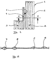
- FIG. 1 shows the evaporator board 1 with its different cooling surfaces 2 and 3 and with the connecting webs 4 and 5 lying in the region of the bends in the further installation process.
- the cooling channel 6 runs in a meandering manner within the evaporator board.
- FIG. 2 shows some enlarged sections of the cooling channel, first in the area of the webs and in the area of the circuit board that will later be located in the cooling room.
- Sections 7 and 8 of cooling channel 6 are partially expanded with the method according to the invention and have a substantially larger cross section than sections 9 and 10 lying in the area of the later interior cooling surface.
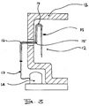
- FIG. 3 shows another evaporator board 11, which is arranged within a schematically illustrated cooling space 12 and is sealed off from the environment by means of the housing insulation 13.
- This evaporator board 11 also has curved web areas 14, 15 and 16, which are finally connected to the compressor 18 via the pipeline 17 outside the cooling chamber.
- the web regions 14, 15 and 16 again show a larger cooling channel cross section, which corresponds approximately to the cross sections 7 and 8 shown in FIG. 2.
- the web regions 14, 15 and 16 again show a larger cooling channel cross section, which corresponds approximately to the cross sections 7 and 8 shown in FIG. 2.
- the evaporator board 11 only a one-sided expansion is provided, which thereby contains a cooling channel corresponding to the cross sections 9 and 10.
Landscapes
- Engineering & Computer Science (AREA)
- Mechanical Engineering (AREA)
- Physics & Mathematics (AREA)
- Thermal Sciences (AREA)
- General Engineering & Computer Science (AREA)
- Heat-Exchange Devices With Radiators And Conduit Assemblies (AREA)
- Pressure Welding/Diffusion-Bonding (AREA)
Applications Claiming Priority (2)
| Application Number | Priority Date | Filing Date | Title |
|---|---|---|---|
| DE4432340 | 1994-09-10 | ||
| DE19944432340 DE4432340C1 (de) | 1994-09-10 | 1994-09-10 | Verfahren zur Herstellung eines Verdampfers für ein Kompressorkühlgerät |
Publications (2)
| Publication Number | Publication Date |
|---|---|
| EP0700737A2 true EP0700737A2 (fr) | 1996-03-13 |
| EP0700737A3 EP0700737A3 (fr) | 1996-06-05 |
Family
ID=6527952
Family Applications (1)
| Application Number | Title | Priority Date | Filing Date |
|---|---|---|---|
| EP95112053A Withdrawn EP0700737A3 (fr) | 1994-09-10 | 1995-07-28 | Procédé de fabrication d'un évaporateur pour une machine frigorifique à compression |
Country Status (3)
| Country | Link |
|---|---|
| EP (1) | EP0700737A3 (fr) |
| DE (1) | DE4432340C1 (fr) |
| HU (1) | HU212748B (fr) |
Cited By (4)
| Publication number | Priority date | Publication date | Assignee | Title |
|---|---|---|---|---|
| US7708053B2 (en) | 2000-06-30 | 2010-05-04 | Alliant Techsystems Inc. | Heat transfer system |
| US8066055B2 (en) | 2000-06-30 | 2011-11-29 | Alliant Techsystems Inc. | Thermal management systems |
| US8109325B2 (en) | 2000-06-30 | 2012-02-07 | Alliant Techsystems Inc. | Heat transfer system |
| US8136580B2 (en) | 2000-06-30 | 2012-03-20 | Alliant Techsystems Inc. | Evaporator for a heat transfer system |
Families Citing this family (7)
| Publication number | Priority date | Publication date | Assignee | Title |
|---|---|---|---|---|
| DE19639115C2 (de) * | 1996-09-24 | 2003-08-07 | Behr Gmbh & Co | Plattenförmiges Wärmeübertragerelement |
| DE19721931A1 (de) * | 1997-05-26 | 1998-12-03 | Krupp Vdm Gmbh | Verfahren zur Herstellung von Wärmetauschern sowie danach hergestellter Wärmetauscher |
| AT409232B (de) * | 1999-10-19 | 2002-06-25 | Vaillant Gmbh | Verdampfer/kondensator einer sorptionspumpe |
| DE102006029821B3 (de) * | 2006-06-28 | 2008-04-03 | Lob Gmbh | Wärmetauscher |
| DE102008051161B4 (de) | 2008-10-10 | 2013-05-29 | Highterm Research Gmbh | Wirbelschichtreaktor sowie Einsatz für einen solchen Wirbelschichtreaktor |
| DE102017005325B4 (de) * | 2017-06-02 | 2026-02-26 | Audi Ag | Verfahren zur Herstellung eines Bodens oder eines Deckels für ein Energiespeichergehäuse und Verfahren zur Herstellung eines Energiespeichergehäuses |
| DE102019110870A1 (de) * | 2019-04-26 | 2020-10-29 | Liebherr-Components Biberach Gmbh | Kühlvorrichtung zum Kühlen einer Energiespeicher- und/oder Elektronikbaugruppe sowie Verfahren zu deren Herstellung |
Citations (2)
| Publication number | Priority date | Publication date | Assignee | Title |
|---|---|---|---|---|
| DE1920424A1 (de) | 1968-04-22 | 1969-11-13 | Olin Mathieson | Verfahren zum Herstellen genau abgegrenzter Schweisszonen auf einem Metallblech oder Metallstreifen |
| DE1552044A1 (de) | 1965-08-24 | 1970-11-26 | Olin Mathieson | Verfahren zur Herstellung von Hohlkoerpern |
Family Cites Families (5)
| Publication number | Priority date | Publication date | Assignee | Title |
|---|---|---|---|---|
| FR1190611A (fr) * | 1956-11-30 | 1959-10-14 | Olin Mathieson | Fabrication d'articles creux par gonflage d'une portion non réunie d'un flan |
| DE1122480B (de) * | 1958-03-06 | 1962-01-25 | Reynolds Metals Co | Verfahren zur Herstellung von Hohlkoerpern durch Aufblaehung von Schichtkoerpern zwishen formbestimmenden Gegenlagern |
| US3196528A (en) * | 1961-12-18 | 1965-07-27 | Olin Mathieson | Metal sheet article and process for making |
| DE1244422B (de) * | 1964-12-29 | 1967-07-13 | Ver Deutsche Metallwerke Ag | Verfahren zum Gluehen kaltverfestigter Verbundbleche |
| GB1176572A (en) * | 1967-05-16 | 1970-01-07 | Olin Mathieson | Method of Forming a Sheet Metal Panel |
-
1994
- 1994-09-10 DE DE19944432340 patent/DE4432340C1/de not_active Expired - Fee Related
-
1995
- 1995-07-28 EP EP95112053A patent/EP0700737A3/fr not_active Withdrawn
- 1995-09-08 HU HU9502636A patent/HU212748B/hu not_active IP Right Cessation
Patent Citations (2)
| Publication number | Priority date | Publication date | Assignee | Title |
|---|---|---|---|---|
| DE1552044A1 (de) | 1965-08-24 | 1970-11-26 | Olin Mathieson | Verfahren zur Herstellung von Hohlkoerpern |
| DE1920424A1 (de) | 1968-04-22 | 1969-11-13 | Olin Mathieson | Verfahren zum Herstellen genau abgegrenzter Schweisszonen auf einem Metallblech oder Metallstreifen |
Cited By (7)
| Publication number | Priority date | Publication date | Assignee | Title |
|---|---|---|---|---|
| US7708053B2 (en) | 2000-06-30 | 2010-05-04 | Alliant Techsystems Inc. | Heat transfer system |
| US8066055B2 (en) | 2000-06-30 | 2011-11-29 | Alliant Techsystems Inc. | Thermal management systems |
| US8109325B2 (en) | 2000-06-30 | 2012-02-07 | Alliant Techsystems Inc. | Heat transfer system |
| US8136580B2 (en) | 2000-06-30 | 2012-03-20 | Alliant Techsystems Inc. | Evaporator for a heat transfer system |
| US8752616B2 (en) | 2000-06-30 | 2014-06-17 | Alliant Techsystems Inc. | Thermal management systems including venting systems |
| US9273887B2 (en) | 2000-06-30 | 2016-03-01 | Orbital Atk, Inc. | Evaporators for heat transfer systems |
| US9631874B2 (en) | 2000-06-30 | 2017-04-25 | Orbital Atk, Inc. | Thermodynamic system including a heat transfer system having an evaporator and a condenser |
Also Published As
| Publication number | Publication date |
|---|---|
| HU212748B (en) | 1996-10-28 |
| DE4432340C1 (de) | 1995-08-24 |
| EP0700737A3 (fr) | 1996-06-05 |
| HU9502636D0 (en) | 1995-11-28 |
| HUT73005A (en) | 1996-06-28 |
Similar Documents
| Publication | Publication Date | Title |
|---|---|---|
| EP3531055B1 (fr) | Échangeur de chaleur à plaques et son procédé de fabrication | |
| EP1305561B1 (fr) | Dispositif de transfert de chaleur | |
| DE69809121T2 (de) | Wärmetauscher | |
| DE2611859A1 (de) | Verfahren zur herstellung von metall-sandwichgebilden | |
| DE3314264A1 (de) | Verfahren zur herstellung von stahl-verbundrohren | |
| EP0122429A1 (fr) | Matériau composite sous forme de barres, tubes, feuillards, tôles ou plaques, possédant des caractéristiques thermomécaniques réversibles et procédé pour sa fabrication | |
| DE4432340C1 (de) | Verfahren zur Herstellung eines Verdampfers für ein Kompressorkühlgerät | |
| DE69729836T2 (de) | Verdampfer | |
| EP1306640B1 (fr) | Plaque tubulaire d'échangeur de chaleur pour gaz d'échappement | |
| EP2766908B1 (fr) | Tube métallique; utilisation d'un tube métallique en tant qu'élément structural; procédé pour produire un tube métallique; élément structural métallique; déflecteur | |
| DE19531035C2 (de) | Verfahren zur Herstellung von Hohlkörpern aus Aluminium oder Aluminiumlegierungen | |
| EP2984420A1 (fr) | Appareil frigorifique muni d'un évaporateur | |
| EP3009780B1 (fr) | Fluide caloporteur | |
| DE102007001430A1 (de) | Wärmetauscher | |
| DE102006002932B4 (de) | Wärmetauscher und Herstellungsverfahren für Wärmetauscher | |
| WO2020127097A1 (fr) | Élément de thermorégulation, dispositif accumulateur de batterie, procédé de fabrication d'un élément de thermorégulation et procédé de fabrication d'un dispositif accumulateur de batterie | |
| DE69215098T2 (de) | Verteiler für parallelfluss-wärmetauscher | |
| CH384008A (de) | Verfahren zur Herstellung von Wärmetauschern | |
| DE2847897A1 (de) | Verfahren zur herstellung eines flachen waermetauschers aus metallblech | |
| DE19854175C1 (de) | Metallschaumfügeverfahren | |
| DE4442817C2 (de) | Verdampfer für ein Kompressorkühlgerät | |
| DE2616586A1 (de) | Anschluss- und verbindungsstuecke fuer kanalbleche und verfahren zu deren herstellung | |
| EP1957893B1 (fr) | Condenseur de fluide frigorifique pour appareil frigorifique | |
| DE102021131552B3 (de) | Verfahren zur Herstellung eines Flachrohrs | |
| EP4015813B1 (fr) | Chambre de combustion, procédé de fabrication d'une chambre de combustion et moteur |
Legal Events
| Date | Code | Title | Description |
|---|---|---|---|
| PUAI | Public reference made under article 153(3) epc to a published international application that has entered the european phase |
Free format text: ORIGINAL CODE: 0009012 |
|
| AK | Designated contracting states |
Kind code of ref document: A2 Designated state(s): AT BE CH DE DK ES FR GB GR IE IT LI NL PT SE |
|
| RAX | Requested extension states of the european patent have changed |
Free format text: SI PAYMENT 950728 |
|
| PUAL | Search report despatched |
Free format text: ORIGINAL CODE: 0009013 |
|
| AK | Designated contracting states |
Kind code of ref document: A3 Designated state(s): AT BE CH DE DK ES FR GB GR IE IT LI NL PT SE |
|
| AX | Request for extension of the european patent |
Free format text: SI PAYMENT 950728 |
|
| 17P | Request for examination filed |
Effective date: 19960711 |
|
| STAA | Information on the status of an ep patent application or granted ep patent |
Free format text: STATUS: THE APPLICATION IS DEEMED TO BE WITHDRAWN |
|
| 18D | Application deemed to be withdrawn |
Effective date: 19980203 |