EP0700855A2 - Andrückwalze für das Andrücken einer laufenden Warenbahn - Google Patents
Andrückwalze für das Andrücken einer laufenden Warenbahn Download PDFInfo
- Publication number
- EP0700855A2 EP0700855A2 EP95113666A EP95113666A EP0700855A2 EP 0700855 A2 EP0700855 A2 EP 0700855A2 EP 95113666 A EP95113666 A EP 95113666A EP 95113666 A EP95113666 A EP 95113666A EP 0700855 A2 EP0700855 A2 EP 0700855A2
- Authority
- EP
- European Patent Office
- Prior art keywords
- pressure roller
- roller according
- pressure
- elastic
- jacket
- Prior art date
- Legal status (The legal status is an assumption and is not a legal conclusion. Google has not performed a legal analysis and makes no representation as to the accuracy of the status listed.)
- Granted
Links
Images

Classifications
-
- B—PERFORMING OPERATIONS; TRANSPORTING
- B65—CONVEYING; PACKING; STORING; HANDLING THIN OR FILAMENTARY MATERIAL
- B65H—HANDLING THIN OR FILAMENTARY MATERIAL, e.g. SHEETS, WEBS, CABLES
- B65H19/00—Changing the web roll
- B65H19/10—Changing the web roll in unwinding mechanisms or in connection with unwinding operations
- B65H19/18—Attaching, e.g. pasting, the replacement web to the expiring web
- B65H19/1805—Flying splicing, i.e. the expiring web moving during splicing contact
- B65H19/181—Flying splicing, i.e. the expiring web moving during splicing contact taking place on the replacement roll
-
- B—PERFORMING OPERATIONS; TRANSPORTING
- B65—CONVEYING; PACKING; STORING; HANDLING THIN OR FILAMENTARY MATERIAL
- B65H—HANDLING THIN OR FILAMENTARY MATERIAL, e.g. SHEETS, WEBS, CABLES
- B65H27/00—Special constructions, e.g. surface features, of feed or guide rollers for webs
-
- B—PERFORMING OPERATIONS; TRANSPORTING
- B65—CONVEYING; PACKING; STORING; HANDLING THIN OR FILAMENTARY MATERIAL
- B65H—HANDLING THIN OR FILAMENTARY MATERIAL, e.g. SHEETS, WEBS, CABLES
- B65H2404/00—Parts for transporting or guiding the handled material
- B65H2404/10—Rollers
- B65H2404/11—Details of cross-section or profile
- B65H2404/112—Means for varying cross-section
-
- B—PERFORMING OPERATIONS; TRANSPORTING
- B65—CONVEYING; PACKING; STORING; HANDLING THIN OR FILAMENTARY MATERIAL
- B65H—HANDLING THIN OR FILAMENTARY MATERIAL, e.g. SHEETS, WEBS, CABLES
- B65H2404/00—Parts for transporting or guiding the handled material
- B65H2404/10—Rollers
- B65H2404/14—Roller pairs
- B65H2404/145—Roller pairs other
- B65H2404/1451—Pressure
-
- B—PERFORMING OPERATIONS; TRANSPORTING
- B65—CONVEYING; PACKING; STORING; HANDLING THIN OR FILAMENTARY MATERIAL
- B65H—HANDLING THIN OR FILAMENTARY MATERIAL, e.g. SHEETS, WEBS, CABLES
- B65H2404/00—Parts for transporting or guiding the handled material
- B65H2404/10—Rollers
- B65H2404/17—Details of bearings
- B65H2404/171—Details of bearings beam supply
Definitions
- the invention relates to a pressure roller for pressing a first running web to a second running web according to the preamble of claim 1.
- the DT 23 31 125 discloses a pressure roller of the generic type, which consists of a double-walled tube rotatably mounted in support arms, which is provided on its outer jacket with a rubber pad. This pressure roller can be moved in the direction of a new supply roll for the gluing process.
- a disadvantage of this pressure roller is that the compressibility of the rubber pad on the tube is limited, so that unevenness of the rotating new supply roll during the gluing process with the running web of an end of a roll can only be insufficiently compensated.
- the invention has for its object to provide a pressure roller easily adaptable to an uneven surface of a rotating supply roll for connecting a running web of material with an adhesive-provided beginning of the supply roll.
- the following advantages are achieved by the invention: as a result of the arrangement of one or more gas-filled cells between the support tube and the elastic pressure jacket, it has become possible to create a pressure roller which can be easily adapted to an uneven surface of a new supply roll for pressing two running paper webs.
- the pressure roller according to the invention has a low mass, which is advantageous for a quick adjustability of the pressure roller.
- a pressure roller designated as a whole by 1, consists of a support tube 2, which has at its two ends 6 a bearing journal supported by a ball bearing 3 4 records.
- the bearing pins 4 are in pivotable arms or in movable adhesive slides z. B. according to DE 41 35 101 A1 known pressing and separating device.
- an annular cover 7 or end plate is placed so that its clear inside diameter rests on the outside diameter of the support tube 2.
- Both covers 3 support with their circumference the ends 8 of an elastic hollow cylindrical pressure jacket 9, so that between the outer jacket surface 11 of the support tube 2 and the inner jacket surface 12 of the jacket 9, a hollow cylindrical space 13 is formed, which a variety of air-filled cells - all named at 14, but not always labeled - records.
- the cells 14 can each have a cylindrical shape, consist of film and overlap side by side and one behind the other (FIG. 3) on a flexible carrier material 16, e.g. B. film, airtight.
- the carrier material 16 thus equipped with gas or air-filled cells 14 can have a width which corresponds to the usable axial length of the pressure roller 1.
- the material 14, 16 can be wound in multiple layers and spirally to the axis of rotation 17 of the pressure roller 1 on the support tube 2, so that the side edges of the carrier material 16 lie against the inside of the annular covers 7.
- the space 13 is thus filled with compressible material 14, 16.
- Such material 14, 16 can consist of commercially available bubble wrap. Parts 2, 3, 4, 6, 7, 8 are duplicated, but only shown one.
- the cells 14 are present in a number not specified.
- Peripheral cells 14 form an outer surface 28, which can serve as the running surface of the pressure roller 1. Expediently, however, the peripheral lateral surface 28 of the cells 14 is surrounded by an elastic pressure jacket 9 so that it forms the running surface. However, it is also possible to connect all cells 14 to one another, e.g. B. by means of tubular connections, so that a defined air balance can take place between the cells 14.
- a pressure roller designated overall by 21, is shown, the supporting tube 2 of which receives an annular flange 22 at each of its two ends 6.
- Both ring flanges 22 each have a circular groove 24 on the mutually facing flanks 23, in each of which the end 8 of an elastic pressure jacket 9 is fastened, so that there is between the outer jacket surface 11 of the support tube 2 and the inner jacket surface 12 of the elastic pressure jacket 9, bounded by the ring flanges 22, a hollow cylindrical space or cell 13 results, in which compressed air can be introduced by means of a valve 26 arranged in the ring flange 22, which can be designed as a check valve.
- the cell 13 is thus also equipped with compressible material, the air pressure in the cell 13 being able to be filled up by means of a known compressed air source and is therefore also adjustable (Fig. 4).
- a hardness of the pressure roller 21 and a so-called "flattening", which arises when pressing against a supply roll, can be set.
- the parts 22, 23, 24 are duplicated. Parts already mentioned in exemplary embodiment 1 are not mentioned again and are equally designed.
- the ends 8 of the elastic pressure jacket 9 can also be shrunk on the outer circumference 27 of the ring flange 27.
- knobs 33; 34 have.
- the knobs 33 are shown only on the inside 31 of the elastic pressure jacket 29 and in FIG. 6 the knobs 34 are shown on the outside 32 of the elastic pressure jacket 36.
- the knobs 33; 34 be conical or cylindrical.
- the elastic pressure sleeves 29; 36 these can be spaced apart on their inside 31 or outside 36 from each other at a distance a, circumferential rings 37; 38 have (designated in Fig. 5 and 6 as the second reference numeral, separated by semicolon).
- a height h of the knobs 33, 34 or of the rings 37, 38 corresponds to at least one thickness d of the elastic pressure jacket 29; 36.
- the rings 37 (FIG. 5) can be rounded at their upper and lower edges, so that they take on an approximately conical to frustoconical shape in cross section.
- the rings 38 are shown with sharp edges.
- the elastic pressure jacket 36 can be provided on its outside instead of the knobs 33 at a distance of approximately 0.25 times a "spikes" made of elastic material, e.g. B. rubber, have a height which is greater than the height h of the knobs 33, 34 or the rings 37, 38th
- an elastic pressure jacket 9 seen in longitudinal section, in a wavy shape.
- the for the elastic pressure jackets 9; 29; 36 material used can e.g. B. consist of rubber.
- the material used for the support tube 2 can consist of metal, glass fiber or carbon fiber reinforced material.
- a pressure roller generally designated 39 is shown, which on the support tube 2 several, for. B. has four gas-filled cells 41, 42, 43, 44 arranged one behind the other in the axial direction 17, each of which can be acted upon separately with gas by means of a valve 47, 48, 49, 50 arranged in the elastic pressure jacket 46. If necessary, a different gas pressure can thus be set for each cell 41 to 44.
Landscapes
- Replacement Of Web Rolls (AREA)
- Registering, Tensioning, Guiding Webs, And Rollers Therefor (AREA)
- Rolls And Other Rotary Bodies (AREA)
Abstract
Description
- Die Erfindung betrifft eine Andrückwalze für das Andrücken einer ersten laufenden Warenbahn an eine zweite laufende Warenbahn entsprechend dem Oberbegriff des Anspruches 1.
- Durch die DT 23 31 125 ist eine gattungsgemäße Andrückwalze bekannt, welche aus einem drehbar in Tragarmen gelagerten doppelwandigen Rohr besteht, welches an seinem Außenmantel mit einer Gummiauflage versehen ist. Diese Andrückwalze ist für den Anklebevorgang in Richtung einer neuen Vorratsrolle bewegbar.
- Nachteilig bei dieser Andrückwalze ist, daß die Kompressibilität der auf dem Rohr befindlichen Gummiauflage jedoch begrenzt ist, so daß Unebenheiten der sich drehenden neuen Vorratsrolle beim Anklebevorgang mit der laufenden Bahn einer zu Ende gehenden Rolle nur ungenügend kompensiert werden können.
- Der Erfindung liegt die Aufgabe zugrunde, eine gut an eine unebene Oberfläche einer rotierenden Vorratsrolle anpaßbare Andrückwalze leichter Bauart für das Verbinden einer laufenden Warenbahn mit einem mit Klebemittel versehenen Anfang der Vorratsrolle zu schaffen.
- Erfindungsgemäß wird diese Aufgabe durch die Merkmale des kennzeichnenden Teils des Anspruches 1 gelöst.
- Durch die Erfindung werden insbesondere folgende Vorteile erzielt: infolge der Anordnung von einer oder mehreren gasgefüllten Zellen zwischen dem Tragrohr und dem elastischen Andrückmantel ist es möglich geworden, eine gut an eine unebene Oberfläche einer neuen Vorratsrolle anpaßbare Andrückwalze für das Andrücken zweier laufenden Papierbahnen zu schaffen. Dabei weist die erfindungsgemäße Andrückwalze eine geringe Masse auf, was für eine schnelle Anstellbarkeit der Andrückwalze vorteilhaft ist. Darüberhinaus ist es zumindest bei einer Ausführungsvariante der Andrückwalze möglich, die Kompressibilität der Andrückwalze sowohl generell als auch über die axiale Länge partiell einstellbar zu gestalten. Letzteres ist besonders vorteilhaft, wenn über die Papierbahnbreite ein Abschnitt oder verschiedene Abschnitte mit einer anderen Härte beaufschlagt werden müssen, z. B. beim Andrücken von sogenannten Klebeetiketten.
- Die Erfindung wird nachfolgend an mehreren Ausführungsbeispielen näher erläutert. Die zugehörigen Zeichnungen zeigen in
- Fig. 1
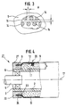
- die Vorderansicht eines Endes einer erfindungsgemäßen Andrückwalze, teilweise im Längsschnitt,
- Fig. 2
- einen Schnitt II - II durch den Andrückmantel der Andrückwalze nach Fig. 1 mit der Darstellung eines Teils des Querschnitts der Andrückwalze,
- Fig. 3
- eine Ansicht A nach Fig. 2 mit Darstellung einer Draufsicht auf die luftgefüllten Zellen,
- Fig. 4
- eine Vorderansicht entsprechend Fig. 1, jedoch bei einem zweiten Ausführungsbeispiel einer Andrückwalze,
- Fig. 5
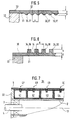
- eine Ausführungsvariante eines elastischen Andrückmantels nach Fig. 4 in ausschnittsweiser vergrößerter Schnittdarstellung,
- Fig. 6
- eine weitere Ausführungsvariante einer elastischen Andrückmantels nach Fig. 4 in ausschnittsweiser vergrößerter Schnittdarstellung,
- Fig. 7
- eine weitere Ausführungsvariante mit mehreren gasgefüllten Zellen in ausschnittsweiser Schnittdarstellung.
- Eine insgesamt mit 1 bezeichnete Andrückwalze besteht aus einem Tragrohr 2, welches an seinen beiden Enden 6 jeweils ein über ein Kugellager 3 gelagerten Lagerzapfen 4 aufnimmt. Die Lagerzapfen 4 sind in schwenkbaren Armen bzw. in verfahrbaren Klebeschlitten z. B. nach der DE 41 35 101 A1 bekannten Andrück- und Trenneinrichhtung gelagert. Auf beiden Enden 6 des Tragrohres 2 ist jeweils ein kreisringförmiger Deckel 7 oder Endscheibe aufgesetzt, so daß dessen lichte Innendurchmesser auf dem Außendurchmesser des Tragrohres 2 aufsitzt. Beide Deckel 3 stützen mit ihrem Umfang jeweils die Enden 8 eines elastischen hohlzylinderförmigen Andrückmantels 9 ab, so daß zwischen der äußeren Mantelfläche 11 des Tragrohres 2 und der inneren Mantelfläche 12 des Mantels 9 ein hohlzylinderförmiger Raum 13 entsteht, welcher eine Vielzahl von luftgefüllten Zellen - alle mit 14 benannt, jedoch nicht immer bezeichnet - aufnimmt. Die Zellen 14 können jeweils eine Zylinderform aufweisen, aus Folie bestehen sowie flächenhaft neben - und hintereinander (Fig. 3) auf eine flexibles Trägermaterial 16, z. B. Folie, luftdicht aufgesetzt sein. Das so mit gas- bzw. luftgefüllten Zellen 14 bestückte Trägermaterial 16 kann eine Breite aufweisen, die der nutzbaren axialen Länge der Andrückwalze 1 entspricht. Das Material 14, 16 kann mehrlagig und spiralförmig zur Rotationsachse 17 der Andrückwalze 1 auf das Tragrohr 2 aufgewickelt sein, so daß die Seitenränder des Trägermaterials 16 innen an den kreisringförmigen Deckeln 7 anliegen. Somit ist der Raum 13 mit kompressiblen Material 14, 16 ausgefüllt. Derartiges Material 14, 16 kann aus handelsüblicher Luftpolsterfolie bestehen. Die Teile 2, 3, 4, 6, 7, 8 sind zweifach vorhanden, jedoch nur einem dargestellt. Die Zellen 14 sind in einer nicht näher bezeichneten Vielzahl vorhanden. Periphere Zellen 14 bilden eine Mantelfläche 28, welche als Lauffläche der Andrückwalze 1 dienen kann. Zweckmäßigerweise ist jedoch die periphere Mantelfläche 28 der Zellen 14 von einem elastischen Andrückmantel 9 umgeben, so daß dieser die Lauffläche bildet. Es ist jedoch auch möglich, alle Zellen 14 untereinander zu verbinden, z. B. mittels rohrförmiger Verbindungen, so daß zwischen den Zellen 14 ein definierter Luftausgleich erfolgen kann.
- In einem zweiten Ausführungsbeispiel ist eine insgesamt mit 21 bezeichnete Andrückwalze dargestellt, deren Tragrohr 2 an seinen beiden Enden 6 jeweils einen Ringflansch 22 aufnimmt. Beide Ringflansche 22 weisen an den einanderzugewandten Flanken 23 jeweils eine kreisförmige Nut 24 auf, in welcher jeweils das Ende 8 eines elastischen Andrückmantels 9 befestigt ist, so daß sich zwischen der äußeren Mantelfläche 11 des Tragrohres 2 sowie der inneren Mantelfläche 12 des elastischen Andrückmantels 9, begrenzt von den Ringflanschen 22, ein hohlzylinderförmiger Raum oder Zelle 13 ergibt, in welcher mittels eines im Ringflansch 22 angeordneten Ventils 26, welches als Rückschlagventil ausgebildet sein kann, Druckluft eingeleitet werden kann. Somit ist die Zelle 13 ebenfalls mit kompressiblen Material ausgestattet, wobei der Luftdruck in der Zelle 13 mittels einer bekannten Druckluftquelle auffüllbar und somit auch einstellbar ist (Fig. 4). Somit ist sowohl eine Härte der Andrückwalze 21 als auch eine sogenannte "Abplattung", welche beim Gegendrücken gegen eine Vorratsrolle entsteht, einstellbar. Die Teile 22, 23, 24 sind zweifach vorhanden. Bereits im Ausführungsbeispiel 1 genannte Teile sind nicht nochmals erwähnt und gleichermaßen ausgebildet.
- Nach einer anderen Ausführungsvariante des zweiten Ausführungsbeispiels können die Enden 8 des elastischen Andrückmantels 9 auch auf dem äußeren Umfang 27 des Ringflansches 27 aufgeschrumpft sein.
- Zur besseren Stabilität eines anderen elastischen Andrückmantels 29; 36 kann dieser auf seiner Innenseite 31 oder Außenseite 32 in axialer sowie in peripherer Richtung voneinander im Abstand a beabstandete Noppen 33; 34 aufweisen. In Fig. 5 sind die Noppen 33 nur auf der Innenseite 31 des elastischen Andrückmantels 29 und in Fig. 6 sind die Noppen 34 auf der Außenseite 32 des elastischen Andrückmantels 36 dargestellt. Dabei können die Noppen 33; 34 kegelförmig oder zylinderförmig ausgebildet sein.
- Nach einer anderen Ausführungsvariante der in Fig. 5 und 6 dargestellten elastischen Andrückmäntel 29; 36 können diese auf ihrer Innenseite 31 oder Außenseite 36 voneinander im Abstand a beabstandete, in peripherer Richtung der Andrückwalze 21 umlaufende Ringe 37; 38 aufweisen (in Fig. 5 und 6 als zweites Bezugszeichen, getrennt mittels Semikolon, bezeichnet). Eine Höhe h der Noppen 33, 34 oder der Ringe 37, 38 entspricht mindestens einer Dicke d des elastischen Andrückmantels 29; 36. Die Ringe 37 (Fig. 5) können an ihren oberen und unteren Kanten abgerundet sein, so daß diese im Querschnitt eine etwa kegelige bis kegelstumpfförmige Form einnehmen. Die Ringe 38 sind scharfkantig dargestellt.
- Nach einer weiteren nichtdargestellten Ausführungsvariante kann der elastische Andrückmantel 36 auf seiner Außenseite statt der Noppen 33 voneinander im Abstand von ca. 0,25 mal a beabstandete "Stacheln" aus elastischem Material, z. B. Gummi, aufweisen mit einer Höhe, welche größer ist als die Höhe h der Noppen 33, 34 oder der Ringe 37, 38.
- Es ist auch weiterhin möglich, einen elastischen Andrückmantel 9, im Längsschnitt gesehen, wellenlinienförmig auszubilden. Das für die elastischen Andrückmäntel 9; 29; 36 verwendete Material kann z. B. aus Gummi bestehen. Das für das Tragrohr 2 verwendete Material kann aus Metall, glasfaser - oder kohlefaserversträrktem Material bestehen.
- Alle Noppen 33, 34, Ringe 37, 38 oder Stacheln sind stoffschlüssig mit dem jeweils genannten elastischen Andrückmantel 9, 29, 36 verbunden.
- Nach einem weiteren Ausführungsbeispiel ist eine insgesamt mit 39 bezeichnete Andrückwalze gezeigt, welche auf dem Tragrohr 2 mehrere, z. B. vier in axialer Richtung 17 hintereinander angeordnete gasgefüllte Zellen 41, 42, 43, 44 aufweist, welche jeweils mittels eines im elastischen Andrückmantel 46 angeordnetem Ventil 47, 48, 49, 50 separat mit Gas beaufschlagbar ist. Damit kann, falls erforderlich, für jede Zelle 41 bis 44 ein unterschiedlicher Gasdruck eingestellt werden.
-
- 1
- Andrückwalze
- 2
- Tragrohr
- 3
- Kugellager
- 4
- Lagerzapfen
- 5
- -
- 6
- Ende (2)
- 7
- Deckel, kreisringförmig (2)
- 8
- Ende (9)
- 9
- Andrückmantel, elastisch (1)
- 10
- -
- 11
- Mantelfläche, äußere (2)
- 12
- Mantelfläche, innere (9)
- 13
- Zelle (11, 12)
- 14
- Zelle, luftgefüllt
- 15
- -
- 16
- Trägermaterial
- 17
- Rotationsachse (1)
- 18
- -
- 19
- -
- 20
- -
- 21
- Andrückwalze
- 22
- Ringflansch
- 23
- Flanke (22)
- 24
- Nut, kreisförmig (22)
- 25
- -
- 26
- Ventil (22)
- 27
- Umfang, äußerer (22)
- 28
- Mantelfläche, peripher (14)
- 29
- Andrückmantel, elastisch
- 30
- -
- 31
- Innenseite (29)
- 32
- Außenseite (29)
- 33
- Noppe
- 34
- Noppe
- 35
- -
- 36
- Andrückmantel, elastisch
- 37
- Ring (29)
- 38
- Ring (36)
- 39
- Andrückwalze
- 40
- -
- 41
- Zelle, luftgefüllt (39)
- 42
- Zelle, luftgefüllt (39)
- 43
- Zelle, luftgefüllt (39)
- 44
- Zelle, luftgefüllt (39)
- 45
- -
- 46
- Andrückmantel, elastisch (39)
- 47
- Ventil (41)
- 48
- Ventil (42)
- 49
- Ventil (43)
- 50
- Ventil (44)
- a
- Abstand (33, 34, 37, 38)
- b
- Abstand (2; 9)
- c
- Abstand (14; 14)
- d
- Dicke (29, 36)
- h
- Höhe (33, 34, 37, 38)
Claims (16)
- Andrückwalze (1; 21; 39) zum Andrücken einer ersten laufenden Warenbahn an den mit einem Klebemittel versehenen Anfang einer auf einer rotierenden Vorratsrolle aufgewickelten zweiten Warenbahn, insbesondere Papierbahn, wobei die Länge des aktiven Teils der Andrückwalze der Breite der Warenbahn entspricht, dadurch gekennzeichnet, daß zwischen einem Tragrohr (2) der Andrückwalze (39) und einem sich koaxial zum Tragrohr (2) erstreckenden elastischen hohlzylinderförmigen Andrückmantel (9; 29; 36) eine einzige (13) oder mehrere gasgefüllte Zellen (14; 41, 42, 43, 44) vorgesehen sind.
- Andrückwalze nach Anspruch 1, dadurch gekennzeichnet, daß die radial außen liegenden Flächen der Zellen (13; 14; 41, 42, 43, 44) selbst Bestandteil des elastischen Andrückmantels (9; 28; 29; 36) sind.
- Andrückwalze nach einem der Ansprüche 1 oder 2, dadurch gekennzeichnet, daß eine Mehrzahl von Zellen (14) über die Länge des Tragrohres (2) gesehen nebeneinander angeordnet sind.
- Andrückwalze nach einem der Ansprüche 1 bis 3, dadurch gekennzeichnet, daß die Zellen (14) auf einem flexiblen Trägermaterial (16) angeordnet sind, welches mehrlagig auf dem Tragrohr (2) angeordnet ist.
- Andrückwalze nach einem der Ansprüche 1 bis 4, dadurch gekennzeichnet, daß die Zellen (14) jeweils geschlossen sind.
- Andrückwalze nach einem der Ansprüche 1 bis 4, dadurch gekennzeichnet, daß die Zellen (14) untereinander verbunden sind.
- Andrückwalze nach Anspruch 1, dadurch gekennzeichnet, daß ein Gasdruck in der einzigen Zelle (13) über ein im elastischen Andrückmantel (9; 29; 36) angeordnetes Ventil (26) einstellbar ist.
- Andrückwalze nach Anspruch 7, dadurch gekennzeichnet, daß der elastische Andrückmantel (29; 36) auf seiner Innenseite (31) oder Außenseite (32) Noppen (33; 34) aufweist.
- Andrückwalze nach Anspruch 8, dadurch gekennzeichnet, daß die Noppen (33) kegelförmig ausgebildet sind.
- Andrückwalze nach Anspruch 8, dadurch gekennzeichnet, daß die Noppen (34) zylinderförmig ausgebildet sind.
- Andrückwalze nach Anspruch 7, dadurch gekennzeichnet, daß der elastische Andrückmantel (29; 36) auf seiner Innen- (31) oder Außenseite (32) voneinander beabstandete, in Umfangsrichtung der Andrückwalze (21) umlaufende Ringe (37; 38) aufweist.
- Andruckwalze nach Anspruch 11, dadurch gekennzeichnet, daß die Ringe (37) an ihren Kanten abgerundet sind.
- Andrückwalze nach einem der Ansprüche 7 bis 12, dadurch gekennzeichnet, daß die Höhe h der Noppen (33; 34) oder Ringe (37; 38) mindestens einer Dicke (d) des elastischen Andrückmantels (29; 36) entspricht.
- Andrückwalze nach Anspruch 7, dadurch gekennzeichnet, daß der elastische Andrückmantel (36) auf seiner Außenseite (32) Stacheln aufweist.
- Andrückwalze nach Anspruch 7, dadurch gekennzeichnet, daß der elastische Andrückmantel (9) im Längsschnitt gesehen, wellenlinienförmig ausgebildet ist.
- Andrückwalze nach Anspruch 1, dadurch gekennzeichnet, daß der Gasdruck bei mehreren in axialer Richtung (17) der Andrückwalze (39) hintereinander angeordneten gasgefüllten Zellen in jeder Zelle (41; 42; 43; 44) separat über jeweils ein im elastischen Andrückmantel angeordnetes Ventil (47; 48; 49; 50) einstellbar ist.
Applications Claiming Priority (2)
| Application Number | Priority Date | Filing Date | Title |
|---|---|---|---|
| DE4431648 | 1994-09-06 | ||
| DE4431648A DE4431648C1 (de) | 1994-09-06 | 1994-09-06 | Andrückwalze für das Andrücken einer laufenden Warenbahn |
Publications (3)
| Publication Number | Publication Date |
|---|---|
| EP0700855A2 true EP0700855A2 (de) | 1996-03-13 |
| EP0700855A3 EP0700855A3 (de) | 1997-02-12 |
| EP0700855B1 EP0700855B1 (de) | 1999-04-14 |
Family
ID=6527493
Family Applications (1)
| Application Number | Title | Priority Date | Filing Date |
|---|---|---|---|
| EP95113666A Expired - Lifetime EP0700855B1 (de) | 1994-09-06 | 1995-08-31 | Andrückwalze für das Andrücken einer laufenden Warenbahn |
Country Status (4)
| Country | Link |
|---|---|
| US (1) | US5634606A (de) |
| EP (1) | EP0700855B1 (de) |
| JP (1) | JP2666892B2 (de) |
| DE (2) | DE4431648C1 (de) |
Families Citing this family (11)
| Publication number | Priority date | Publication date | Assignee | Title |
|---|---|---|---|---|
| US6257133B1 (en) | 1999-03-15 | 2001-07-10 | International Paper | Method and apparatus for controlling cross directional nip dynamics |
| US6378434B1 (en) * | 2000-03-07 | 2002-04-30 | Baldwin Graphicsystem, Inc. | Adjustable matte for handling sheets in a printing press and method of using same |
| US6905119B2 (en) * | 2002-06-19 | 2005-06-14 | Hewlett-Packard Development Company, L.P. | Pressurized roller |
| DE102004023565A1 (de) * | 2004-05-13 | 2005-12-08 | Voith Paper Patent Gmbh | Presswalze |
| KR20070072877A (ko) * | 2004-10-22 | 2007-07-06 | 코닌클리케 필립스 일렉트로닉스 엔.브이. | 압력 컨트롤을 구비한 롤러 마이크로-컨택트 프린터 |
| US20080229941A1 (en) * | 2007-03-19 | 2008-09-25 | Babak Heidari | Nano-imprinting apparatus and method |
| US8518633B2 (en) * | 2008-01-22 | 2013-08-27 | Rolith Inc. | Large area nanopatterning method and apparatus |
| US20100113237A1 (en) * | 2008-11-05 | 2010-05-06 | Chun-Tsai Chen | Inflatable shaft |
| US20160229206A1 (en) * | 2015-02-09 | 2016-08-11 | Seiko Epson Corporation | Print apparatus and print method |
| IT202200006755A1 (it) * | 2022-04-06 | 2023-10-06 | Guglielmo Biagiotti | Rullo per il trattamento di materiale in nastro, in particolare per materiale cartaceo |
| CN116833277B (zh) * | 2023-08-30 | 2023-11-14 | 潍坊华宝机械制造有限公司 | 一种沟槽管件槽口滚压机 |
Citations (2)
| Publication number | Priority date | Publication date | Assignee | Title |
|---|---|---|---|---|
| DE2331125B1 (de) | 1973-06-19 | 1974-08-01 | Maschinenfabrik Augsburg-Nuernberg Ag, 8900 Augsburg | Andrückwalze zum Herbeiführen des Anklebens einer neuen Rolle an die ablaufende Bahn insbesondere bei Rollensternen von Rotationsdruckmaschinen |
| DE4135101A1 (de) | 1991-10-24 | 1993-04-29 | Koenig & Bauer Ag | Bahnzufuehrungsvorrichtung fuer papierrollenwechsel bei rotationsdruckmaschinen |
Family Cites Families (22)
| Publication number | Priority date | Publication date | Assignee | Title |
|---|---|---|---|---|
| CH388699A (de) * | 1960-07-04 | 1965-02-28 | Benninger Ag Maschf | Biegungsfreie Walze |
| US3235906A (en) * | 1964-06-18 | 1966-02-22 | Fmc Corp | Film spreading apparatus |
| US3470948A (en) * | 1966-05-18 | 1969-10-07 | Kleinewefers Soehne Maschf | Bend-free roller for calenders,rolling mills,and the like |
| FR1509125A (fr) * | 1966-11-30 | 1968-01-12 | Papeteries De Stenay | Rouleau de laminage |
| GB1203629A (en) * | 1966-11-30 | 1970-08-26 | Stenay Papeterie | Improved rolling or calendering roll |
| US3493161A (en) * | 1967-04-17 | 1970-02-03 | Eastman Kodak Co | Web support roller surface |
| SE324991B (de) * | 1969-07-08 | 1970-06-15 | Sandvikens Jernverks Ab | |
| DE1940175A1 (de) * | 1969-08-07 | 1971-02-18 | Berthold Zipfel | Walze zur Druckbehandlung flaechiger Materialien |
| GB1349744A (en) * | 1970-06-05 | 1974-04-10 | Crone B S | Continuous web joining apparatus |
| US3618869A (en) * | 1970-06-30 | 1971-11-09 | Ibm | Servoing mechanism for improved typewriter ribbon spooling |
| US3972488A (en) * | 1971-02-12 | 1976-08-03 | International Paper Company | Expandable chuck |
| US3917185A (en) * | 1972-11-24 | 1975-11-04 | Sonoco Products Co | Business machine core |
| US3812561A (en) * | 1973-01-15 | 1974-05-28 | W Lundgren | Temple roll |
| US4425695A (en) * | 1979-01-16 | 1984-01-17 | Rengo Kabushiki Kaisha (Rengo Co., Ltd.) | Rolls for use in corrugated fibreboard production system |
| US4327467A (en) * | 1980-05-27 | 1982-05-04 | Goodyear Aerospace Corporation | Inflated shell structure for curing or embossing roller |
| DE3105171C2 (de) * | 1981-02-13 | 1983-03-17 | Kleinewefers Gmbh, 4150 Krefeld | Schleppwalze zur Druckbehandlung von Warenbahnen |
| US4541585A (en) * | 1983-09-06 | 1985-09-17 | Beloit Corporation | Compliant drum and rider roll |
| JPH032431Y2 (de) * | 1985-06-27 | 1991-01-23 | ||
| JP2668881B2 (ja) * | 1987-07-17 | 1997-10-27 | ソニー株式会社 | 画像信号の高能率符号化装置 |
| EP0562266B1 (de) * | 1992-03-26 | 2000-07-12 | J.M. Voith GmbH | Wickelmaschine zum Aufwickeln einer Bahn, insbesondere einer Papierbahn |
| DE4222880C2 (de) * | 1992-07-11 | 2003-09-18 | Voith Paper Patent Gmbh | Splicevorrichtung |
| US5431358A (en) * | 1993-07-26 | 1995-07-11 | Alexander, Iii; William J. | Web roll support apparatus and method |
-
1994
- 1994-09-06 DE DE4431648A patent/DE4431648C1/de not_active Expired - Fee Related
-
1995
- 1995-08-31 EP EP95113666A patent/EP0700855B1/de not_active Expired - Lifetime
- 1995-08-31 DE DE59505634T patent/DE59505634D1/de not_active Expired - Fee Related
- 1995-09-05 US US08/523,128 patent/US5634606A/en not_active Expired - Fee Related
- 1995-09-06 JP JP7229355A patent/JP2666892B2/ja not_active Expired - Lifetime
Patent Citations (2)
| Publication number | Priority date | Publication date | Assignee | Title |
|---|---|---|---|---|
| DE2331125B1 (de) | 1973-06-19 | 1974-08-01 | Maschinenfabrik Augsburg-Nuernberg Ag, 8900 Augsburg | Andrückwalze zum Herbeiführen des Anklebens einer neuen Rolle an die ablaufende Bahn insbesondere bei Rollensternen von Rotationsdruckmaschinen |
| DE4135101A1 (de) | 1991-10-24 | 1993-04-29 | Koenig & Bauer Ag | Bahnzufuehrungsvorrichtung fuer papierrollenwechsel bei rotationsdruckmaschinen |
Also Published As
| Publication number | Publication date |
|---|---|
| JPH08169601A (ja) | 1996-07-02 |
| US5634606A (en) | 1997-06-03 |
| JP2666892B2 (ja) | 1997-10-22 |
| EP0700855B1 (de) | 1999-04-14 |
| EP0700855A3 (de) | 1997-02-12 |
| DE4431648C1 (de) | 1996-01-18 |
| DE59505634D1 (de) | 1999-05-20 |
Similar Documents
| Publication | Publication Date | Title |
|---|---|---|
| DE3501635C2 (de) | ||
| DE3105171C2 (de) | Schleppwalze zur Druckbehandlung von Warenbahnen | |
| AT393523B (de) | Presswalze, die zum behandeln bahnfoermigen gutes, vorzugsweise zum entwaessern einer faserstoffbahn dient | |
| DE1575639B2 (de) | Walze und Verfahren zum Herstellen derselben | |
| EP0406172B1 (de) | Vorrichtung zum Aufbringen einer weichelastischen Schicht auf Walzen für graphische Maschinen | |
| EP0700855B1 (de) | Andrückwalze für das Andrücken einer laufenden Warenbahn | |
| DE3338487A1 (de) | Presswalze | |
| EP0141141B2 (de) | Durchbiegungseinstellwalze | |
| DE2612375C2 (de) | Spannkopf für die die Kernrohre von Wickeln aus Papier, Kunststoffolien oder dergleichen | |
| DE4026007C2 (de) | Durchbiegungseinstellwalze | |
| EP3302930B1 (de) | Kalibriereinrichtung und verfahren zum kalibrieren eines folienschlauches | |
| EP0045856B1 (de) | Schweissvorrichtung zur Herstellung hohlzylindrischer Körper | |
| DE2025849B2 (de) | Uberfuhrtrommel von Bogenrota tionsdruckmaschinen mit Vorrichtungen zum Verhindern des Abschmierens | |
| DE2132823A1 (de) | Rollenspindel zum Greifen der Wickelhuelsen fuer Papierrollen u. dgl. | |
| EP0406171B1 (de) | Verfahren und Vorrichtung zur Herstellung von Klebewalzen für Rollenwechsler von bahnverarbeitenden Maschinen insbesondere Rollenrotations-Druckmaschinen | |
| DE2821586A1 (de) | Expandierbarer spulenhalter | |
| DE3126716A1 (de) | Abdichtanordnung | |
| DE19521859C2 (de) | Durchbiegungssteuerbare Walze | |
| EP0470332A1 (de) | Walze zum Führen und Strecken von Bändern und/oder Folienbahnen | |
| WO1993022572A1 (de) | Rollenlager | |
| DE3642090C1 (de) | Einseitige Wellpappenmaschine | |
| DE3546650C2 (en) | Press casing | |
| DE4407828A1 (de) | Walze, insbesondere für Textilbehandlungsmaschinen | |
| CH658496A5 (de) | Schlauchquetschpumpe. | |
| DE2636868A1 (de) | Spule fuer einen gekruemmten stabbreithalter, sowie damit ausgestatteter breithalter |
Legal Events
| Date | Code | Title | Description |
|---|---|---|---|
| PUAI | Public reference made under article 153(3) epc to a published international application that has entered the european phase |
Free format text: ORIGINAL CODE: 0009012 |
|
| AK | Designated contracting states |
Kind code of ref document: A2 Designated state(s): CH DE FR GB IT LI SE |
|
| PUAL | Search report despatched |
Free format text: ORIGINAL CODE: 0009013 |
|
| AK | Designated contracting states |
Kind code of ref document: A3 Designated state(s): CH DE FR GB IT LI SE |
|
| 17P | Request for examination filed |
Effective date: 19970807 |
|
| 17Q | First examination report despatched |
Effective date: 19970911 |
|
| GRAG | Despatch of communication of intention to grant |
Free format text: ORIGINAL CODE: EPIDOS AGRA |
|
| GRAG | Despatch of communication of intention to grant |
Free format text: ORIGINAL CODE: EPIDOS AGRA |
|
| GRAH | Despatch of communication of intention to grant a patent |
Free format text: ORIGINAL CODE: EPIDOS IGRA |
|
| RAP1 | Party data changed (applicant data changed or rights of an application transferred) |
Owner name: KOENIG & BAUER AKTIENGESELLSCHAFT |
|
| GRAH | Despatch of communication of intention to grant a patent |
Free format text: ORIGINAL CODE: EPIDOS IGRA |
|
| GRAA | (expected) grant |
Free format text: ORIGINAL CODE: 0009210 |
|
| AK | Designated contracting states |
Kind code of ref document: B1 Designated state(s): CH DE FR GB IT LI SE |
|
| REG | Reference to a national code |
Ref country code: CH Ref legal event code: EP |
|
| REF | Corresponds to: |
Ref document number: 59505634 Country of ref document: DE Date of ref document: 19990520 |
|
| ITF | It: translation for a ep patent filed | ||
| GBT | Gb: translation of ep patent filed (gb section 77(6)(a)/1977) |
Effective date: 19990520 |
|
| ET | Fr: translation filed | ||
| PLBE | No opposition filed within time limit |
Free format text: ORIGINAL CODE: 0009261 |
|
| STAA | Information on the status of an ep patent application or granted ep patent |
Free format text: STATUS: NO OPPOSITION FILED WITHIN TIME LIMIT |
|
| 26N | No opposition filed | ||
| PGFP | Annual fee paid to national office [announced via postgrant information from national office to epo] |
Ref country code: GB Payment date: 20010725 Year of fee payment: 7 |
|
| PGFP | Annual fee paid to national office [announced via postgrant information from national office to epo] |
Ref country code: FR Payment date: 20010820 Year of fee payment: 7 |
|
| PGFP | Annual fee paid to national office [announced via postgrant information from national office to epo] |
Ref country code: SE Payment date: 20010822 Year of fee payment: 7 |
|
| PGFP | Annual fee paid to national office [announced via postgrant information from national office to epo] |
Ref country code: CH Payment date: 20010904 Year of fee payment: 7 |
|
| REG | Reference to a national code |
Ref country code: GB Ref legal event code: IF02 |
|
| PG25 | Lapsed in a contracting state [announced via postgrant information from national office to epo] |
Ref country code: LI Free format text: LAPSE BECAUSE OF NON-PAYMENT OF DUE FEES Effective date: 20020831 Ref country code: GB Free format text: LAPSE BECAUSE OF NON-PAYMENT OF DUE FEES Effective date: 20020831 Ref country code: CH Free format text: LAPSE BECAUSE OF NON-PAYMENT OF DUE FEES Effective date: 20020831 |
|
| PG25 | Lapsed in a contracting state [announced via postgrant information from national office to epo] |
Ref country code: SE Free format text: LAPSE BECAUSE OF NON-PAYMENT OF DUE FEES Effective date: 20020901 |
|
| REG | Reference to a national code |
Ref country code: CH Ref legal event code: PL |
|
| GBPC | Gb: european patent ceased through non-payment of renewal fee |
Effective date: 20020831 |
|
| PG25 | Lapsed in a contracting state [announced via postgrant information from national office to epo] |
Ref country code: FR Free format text: LAPSE BECAUSE OF NON-PAYMENT OF DUE FEES Effective date: 20030430 |
|
| EUG | Se: european patent has lapsed | ||
| REG | Reference to a national code |
Ref country code: FR Ref legal event code: ST |
|
| PGFP | Annual fee paid to national office [announced via postgrant information from national office to epo] |
Ref country code: DE Payment date: 20040927 Year of fee payment: 10 |
|
| PG25 | Lapsed in a contracting state [announced via postgrant information from national office to epo] |
Ref country code: IT Free format text: LAPSE BECAUSE OF NON-PAYMENT OF DUE FEES;WARNING: LAPSES OF ITALIAN PATENTS WITH EFFECTIVE DATE BEFORE 2007 MAY HAVE OCCURRED AT ANY TIME BEFORE 2007. THE CORRECT EFFECTIVE DATE MAY BE DIFFERENT FROM THE ONE RECORDED. Effective date: 20050831 |
|
| PG25 | Lapsed in a contracting state [announced via postgrant information from national office to epo] |
Ref country code: DE Free format text: LAPSE BECAUSE OF NON-PAYMENT OF DUE FEES Effective date: 20060301 |