EP0701033B1 - Panneau architectural - Google Patents
Panneau architectural Download PDFInfo
- Publication number
- EP0701033B1 EP0701033B1 EP95111078A EP95111078A EP0701033B1 EP 0701033 B1 EP0701033 B1 EP 0701033B1 EP 95111078 A EP95111078 A EP 95111078A EP 95111078 A EP95111078 A EP 95111078A EP 0701033 B1 EP0701033 B1 EP 0701033B1
- Authority
- EP
- European Patent Office
- Prior art keywords
- face
- underlying structural
- structural member
- projection
- members
- Prior art date
- Legal status (The legal status is an assumption and is not a legal conclusion. Google has not performed a legal analysis and makes no representation as to the accuracy of the status listed.)
- Expired - Lifetime
Links
- 239000000853 adhesive Substances 0.000 claims description 19
- 230000001070 adhesive effect Effects 0.000 claims description 19
- 239000006260 foam Substances 0.000 claims description 11
- 230000008878 coupling Effects 0.000 claims description 9
- 238000010168 coupling process Methods 0.000 claims description 9
- 238000005859 coupling reaction Methods 0.000 claims description 9
- 229910000838 Al alloy Inorganic materials 0.000 claims description 4
- 239000000463 material Substances 0.000 claims description 4
- 239000000203 mixture Substances 0.000 claims description 4
- 229920003002 synthetic resin Polymers 0.000 claims description 4
- 239000000057 synthetic resin Substances 0.000 claims description 4
- 229920005989 resin Polymers 0.000 claims description 3
- 239000011347 resin Substances 0.000 claims description 3
- 238000010276 construction Methods 0.000 description 3
- 239000004576 sand Substances 0.000 description 2
- TVEXGJYMHHTVKP-UHFFFAOYSA-N 6-oxabicyclo[3.2.1]oct-3-en-7-one Chemical compound C1C2C(=O)OC1C=CC2 TVEXGJYMHHTVKP-UHFFFAOYSA-N 0.000 description 1
- 230000010485 coping Effects 0.000 description 1
- 230000001419 dependent effect Effects 0.000 description 1
- 230000002708 enhancing effect Effects 0.000 description 1
- 239000006261 foam material Substances 0.000 description 1
- 230000013011 mating Effects 0.000 description 1
- 230000002123 temporal effect Effects 0.000 description 1
Images




Classifications
-
- E—FIXED CONSTRUCTIONS
- E04—BUILDING
- E04C—STRUCTURAL ELEMENTS; BUILDING MATERIALS
- E04C2/00—Building elements of relatively thin form for the construction of parts of buildings, e.g. sheet materials, slabs, or panels
- E04C2/44—Building elements of relatively thin form for the construction of parts of buildings, e.g. sheet materials, slabs, or panels characterised by the purpose
- E04C2/52—Building elements of relatively thin form for the construction of parts of buildings, e.g. sheet materials, slabs, or panels characterised by the purpose with special adaptations for auxiliary purposes, e.g. serving for locating conduits
- E04C2/526—Building elements of relatively thin form for the construction of parts of buildings, e.g. sheet materials, slabs, or panels characterised by the purpose with special adaptations for auxiliary purposes, e.g. serving for locating conduits with adaptations not otherwise provided for, for connecting, transport; for making impervious or hermetic, e.g. sealings
-
- E—FIXED CONSTRUCTIONS
- E04—BUILDING
- E04F—FINISHING WORK ON BUILDINGS, e.g. STAIRS, FLOORS
- E04F13/00—Coverings or linings, e.g. for walls or ceilings
- E04F13/07—Coverings or linings, e.g. for walls or ceilings composed of covering or lining elements; Sub-structures therefor; Fastening means therefor
- E04F13/08—Coverings or linings, e.g. for walls or ceilings composed of covering or lining elements; Sub-structures therefor; Fastening means therefor composed of a plurality of similar covering or lining elements
- E04F13/0862—Coverings or linings, e.g. for walls or ceilings composed of covering or lining elements; Sub-structures therefor; Fastening means therefor composed of a plurality of similar covering or lining elements composed of a number of elements which are identical or not, e.g. carried by a common web, support plate or grid
Definitions
- the present invention relates to architectural panels for building a fence, a gate or a building wall.
- a conventional fence is built by fixing and stacking concrete blocks side by side and one on another with readymixed concrete. It is however difficult to build fences having various appearances with such stacked blocks.
- the structure as disclosed in, for example, Japanese Examined Utility Model Publication No. 22042/1994 may be employed. According to the structure disclosed in the publication, a groove is formed in the bed or underlying structural member such as a block, a projection or a weir-shaped projection is formed in the back of the face member, such as a tile, and the projection of the face member is fitted in and adhered to the groove of the bed, so that the face member is attached to the bed.
- the projection of the face member With the projection of the face member fitted in the groove of the bed, however, the projection of the face member may be broken during transportation.
- the groove should be made narrow (generally, about 3 mm). This requires that the projection should also be formed narrow, so that the projection becomes easier to break. Further, if a projection is formed in a brittle face member, it is easily broken when fitted in the groove in the bed. Similar problems arise when face members are attached to beds to construct the facing of a gate or the wall of a building.
- NL-A 7 016 713 discloses an architectural panel constructed by a coupling structure of two pairs of connected bodies and connectors. There is provided a facing member with a plurality of smaller protrusions for fitting the facing member to an underlying structural member.
- FR-A-1 578 821 discloses a similar multiple protrusion arrangement.
- NL-A 7 016 713 as well as FR-A-1 578 821 do not disclose the use of synthesized resin foam material and do not refer to the transportation of facing members and underlying structural members.
- an architectural panel having a face member to be fitted to a bed or underlying structural member of a fence, a gate or a wall of a building, the face member having a projection or projections formed on a back thereof and a groove or holes formed on the back thereof in such a way that the projection or projections of the face member are fitted in a groove or holes of another face member which makes a pair with the former face member.
- the face member has a base made of a foam member and a mixture of an incombustible powdery material and an incombustible adhesive is coated on the surface of the base of the face member to provide a stony finish.
- the bed or underlying structural member is made of a synthetic resin foam member.
- a through hole may be formed in the bed or underlying strucutral member and a support of a fence may be made of an aluminium alloy extruded shape, whereby the through hole is fitted over the support to attach the bed to the support. Further, holes may be formed in the top and bottom of the bed or underlying structural member and vertically adjoining beds may be coupled by a coupling member fitted in the holes in the adjoining beds.
- the face member of this invention is attached to the bed by fitting the projection or groove provided on the back of the face member in or on the groove or projection of the bed and adhering those projection and groove.
- the projection and groove or holes of one face member are fitted in and on the groove or holes and projection of another face member so that those projections are protected between two face members.
- reference numeral "1" denotes a support made of an aluminum alloy extruded shape whose bottom end is buried in a concrete sill 2
- reference numeral "3” denotes the bed of a fence
- reference numeral "4" denotes a face member.
- the bed 3 of this example is made of a synthetic foam member, and has a through hole 3a in the up and down direction, a projection 3b at the bottom and a recess 3c at the top.
- a groove 3d for attachment to the face member 4 is formed horizontally in one side of the bed 3 (it may be formed on both sides).
- the face member 4 has a base 4a and a top layer 4b.
- the base 4a is made of a synthetic resin foam member
- the top layer 4b is formed by a dried uniform coat of a mixture of an incombustible powdery material, such as sand or gravel, and an incombustible, weather-resistive synthetic resin adhesive. Accordingly, the top layer 4b has a stony finish.
- a projection (weir-shaped projection) 4c having substantially the same height as the depth of the groove 3d formed in the bed 3 is formed horizontally on the back of the face member 4.
- a groove 4d is formed in the back of the face member 4, in parallel to and adjacent to the projection 4c. The groove 4d has substantially the same depth as the height of the projection 4c and is slightly wider than the projection 4c.
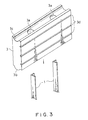
- Fig. 2 shows the face member 4 adhered only to a part of the bed 3.
- a total of six face members 4 are attached to a single bed 3, in two rows horizontally with three face members 4 arranged in the vertical direction in each row.
- the correlation between the quantities of the bed 3 and the face members 4 may however be changed in various ways; for example, a single face member 4 may be attached to a single bed 3. In adhering the face member 4 to the bed 3 by the adhesive 5, the groove 4d in the face member 4 holds the adhesive 5, thus preventing the downward flow of the adhesive 5.
- the top of the support 1 may be designed to protrude above the bed 3, so that another member, such as coping or mesh fence, can be attached to the protruding portion to build a fence.
- the face members 4 are joined with the projections 4c protected therebetween by fitting the projection 4c of one face member 4 into the groove 4d of the mating face member 4, as shown in Fig. 1B. Accordingly, the projections 4c are protected and prevented from being broken during transportation.
- Sand, gravel or the like are adhered on the top layer 4b of the face member 4 by an adhesive, yielding the stony-finished face member 4, and the bed 3 is covered with those face members 4 so that the face members 4, though being light, have an increased strength.
- the bed 3 and the face member 4, if made of a foam member to reduce their weights as in this embodiment, facilitate the construction and transportation of the architectural panel. Further, even if the bed 3 is broken down and falls on a pedestrian at the time of an earthquake, the pedestrian is less likely to be injured.
- a coupling member 6 of a foam member which becomes thinner toward the top and bottom ends to have a tapered shape, is fitted in the through holes of vertically adjoining beds 3 to connect those beds 3.
- the beds 3 are joined in this manner to build a fence.
- the through hole 3a has tapered top and bottom ends 3e to match with the taper shape of the coupling member 6.
- This example has such an advantage that the support 1 should not necessarily be provided so that a fence is built easily and at a low cost.
- one side or the other side of the through hole 3a or the coupling member 6 may be designed to have a polygonal or elliptical cross section.
- the projection 4c of the face member 4 is fitted in the groove 3d provided in the bed 3 and the groove 4d of the face member 4 is fitted and adhered onto a projection 3f provided on the bed 3 by the adhesive 5, thereby enhancing the bonding strength of the face member 4.
- the fitting of this projection 3f into the groove 4d may serve to position the face member 4 or enhance the coupling strength, while the projection 4c of the face member 4 may be loosely fitted in the groove 3d of the bed 3.
- Fig. 7 shows an example wherein a gate is built.
- a support 7 made of an aluminum alloy extruded section is secured to the sill 2.
- a bed 8 made of a foam member is attached to the support 7 by fitting its hole 8a over the support 7.
- the projection 4c of the face member 4 is fitted in a groove 8b provided in the outer surface of the bed 8 and is secured to the groove 8b by an adhesive.
- the beds 8 are fitted over the support 7 one on another, facilitating the construction, and the beds 8 are supported by the support 7 to be prevented from being shifted.
- the built gate has an enhanced strength.
- Fig. 8 shows an example in which the wall of a building is constructed by the panels of this invention.
- a bed 11 made of a foam member or the like is attached to a stud 9 by a securing member 10 or an adhesive and the projection 4c of the face member 4 is fitted and secured in a groove 11a of the bed 11 by the adhesive 5 so that the bed 11 and the face member 4 are attached together.
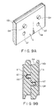
- Fig. 9A shows another example of the face member embodying this invention
- Fig. 9B shows two face members of this type combined.
- a plurality of projections 4e are formed side by side at the back of the face member 4, and holes 4f equal in number to the projections 4e are provided at the same intervals as the projections 4e.
- the projections 4e and holes 4f of one face member are fitted in and on the holes 4f and projections of another face member so that the face members are attached, back to back, to each other.
- the projections 4e are fitted in the grooves 3d, 8b or 11a or the holes so that the face member 4 is attached to the bed 3, 8 or 11.
- grooves may be provided in place of the holes 4f.
- the shapes of the projection 4e and the hole 4f may be altered in various other forms as long as both can be fitted together.
- a groove or holes may be formed in a concrete block already placed in position so that the projections 4c, 4e of the face member 4 can be securely fitted in that groove.
- the face members 4 of this invention may be attached to such existing concrete blocks to build a fence.
- the specific shapes of the bed 3 and the face member 4 and the attachment therebetween are not limited to the illustrated ones and may be modified in various other forms.
- two or more projections 4c may be provided in the face member 4 and two or more grooves 4d may be formed in the face member 4.
- the ends of the beds 3 may be butted against each other at right angles or in an inclined manner.
Landscapes
- Engineering & Computer Science (AREA)
- Architecture (AREA)
- Civil Engineering (AREA)
- Structural Engineering (AREA)
- Fencing (AREA)
- Finishing Walls (AREA)
- Panels For Use In Building Construction (AREA)
- Gates (AREA)
Claims (5)
- Panneau architectural comprenant une pluralité d'éléments de façade (4), un élément structurel sous-jacent (3) et un adhésif (5) destiné à fixer lesdits éléments de façade (4) audit élément structurel sous-jacent (3) ;chaque élément de façade (4) comporte une base (4a) en mousse de résine synthétique, et un mélange d'un matériau en poudre incombustible et d'un adhésif incombustible est enrobé sur la face avant de ladite base (4a) dudit élément de façade (4) pour donner un fini de pierre ;chaque élément de façade (4) comporte une saillie linéaire (4c) et une rainure linéaire (4d), le long de sa face arrière, lesdites saillie (4c) et rainure (4d) étant parallèles entre elles et traversent entièrement ledit élément de façade (4) ;chaque rainure (4d) a pratiquement la même profondeur, à partir de ladite face arrière, que la hauteur de ladite saillie (4c), à partir de ladite face arrière, et une largeur supérieure à celle de ladite saillie (4c) ;la disposition permettant de joindre, arrière contre arrière, les deux éléments de façade, avec saillies (4c) et rainures (4d) verrouillées ensemble pour protéger lesdites saillies et rainures pendant le transport et le stockage ;ledit élément structurel sous-jacent (3) présente des rainures (3d), le long de sa surface ;chaque élément de façade (4) est fixé audit élément structurel sous-jacent (3) en ajustant ladite saillie (4c), sur sa face arrière, dans une desdites rainures (3d) formées dans la face avant dudit élément structurel sous-jacent (3d) etledit adhésif (5) est appliqué auxdites rainures (3d) dudit élément structurel sous-jacent (3) et desdits éléments de façade (4) de façon que ledit élément structurel sous-jacent (3) et lesdits éléments de façade (4) soient fixés les uns aux autres, ladite face arrière desdits éléments de façade (4) touchant ladite face avant dudit élément structurel sous-jacent (3), et ladite rainure (4d) dudit élément de façade (4) retenant ledit adhésif (5).
- Panneau architectural comprenant une pluralité d'éléments de façade (4), un élément structurel sous-jacent (3) et un adhésif (5) destiné à fixer lesdits éléments de façade (4) audit élément structurel sous-jacent (3) ;chaque élément de façade (4) comporte une base (4a) en mousse de résine synthétique, et un mélange d'un matériau en poudre incombustible et d'un adhésif incombustible est enrobé sur la face avant de ladite base (4a) dudit élément de façade (4) pour donner un fini de pierre ;chaque élément de façade (4) comporte des saillies (4e) et des trous (4f), formés sur sa face arrière respectivement ;chaque trou (4f) a pratiquement la même profondeur, à partir de ladite face arrière, que la hauteur de ladite saillie (4e), à partir de ladite face arrière, et une largeur supérieure à celle de ladite saillie (4e) ;la disposition permettant aux deux éléments de façade d'être joints, arrière contre arrière, avec saillies (4e) et trous (4f) verrouillées ensemble pour protéger lesdits saillies et trous, pendant le transport et le stockage ;ledit élément structurel sous-jacent (3) présente des rainures (3d), le long de sa surface ;chaque élément de façade (4) est fixé audit élément structurel sous-jacent (3) en ajustant ladite saillie (4e), sur sa dite face arrière, dans un desdits trous (3f) formées dans la face avant dudit élément structurel sous-jacent (3d) etledit adhésif (5) est appliqué aux dites rainures (3d) dudit élément structurel sous-jacent (3) et desdits éléments de façade (4) de façon que ledit élément structurel sous-jacent (3) et lesdits éléments de façade (4) soient fixés les uns aux autres, ladite face arrière desdits éléments de façade (4) touchant ladite face avant dudit élément structurel sous-jacent (3), et ledit trou (4f) dudit élément de façade (4) retenant ledit adhésif (5).
- Panneau architectural suivant la revendication 1 ou 2, dans lequel ledit élément structurel sous-jacent (3) est fait d'un élément synthétique de mousse de résine.
- Panneau architectural suivant l'une quelconque des revendications précédentes, dans lequel un trou de part en part (3a) est formé dans ledit élément structurel sous-jacent (3) et un support (1) de clôture est une forme extrudée en alliage d'aluminium, de façon à ajuster ledit trou (3a) sur ledit support (1) pour monter ledit élément structurel sous-jacent (3) sur ledit support (1).
- Panneau architectural suivant l'une quelconque des revendications précédentes, dans lequel des trous (3a) sont percés dans un dessus et dans un fond dudit élément structurel sous-jacent (3) et des éléments structurels sous-jacents (3), verticalement joints, sont couplés par un élément de couplage (6) ajusté dans lesdits trous joints (3a) dans lesdits éléments structurels sous-jacents (3).
Applications Claiming Priority (3)
| Application Number | Priority Date | Filing Date | Title |
|---|---|---|---|
| JP242297/94 | 1994-09-10 | ||
| JP6242297A JP2644196B2 (ja) | 1994-09-10 | 1994-09-10 | 建築用パネル |
| JP24229794 | 1994-09-10 |
Publications (2)
| Publication Number | Publication Date |
|---|---|
| EP0701033A1 EP0701033A1 (fr) | 1996-03-13 |
| EP0701033B1 true EP0701033B1 (fr) | 2001-10-17 |
Family
ID=17087145
Family Applications (1)
| Application Number | Title | Priority Date | Filing Date |
|---|---|---|---|
| EP95111078A Expired - Lifetime EP0701033B1 (fr) | 1994-09-10 | 1995-07-14 | Panneau architectural |
Country Status (8)
| Country | Link |
|---|---|
| US (1) | US5566517A (fr) |
| EP (1) | EP0701033B1 (fr) |
| JP (1) | JP2644196B2 (fr) |
| BR (1) | BR9503974A (fr) |
| CA (1) | CA2154493C (fr) |
| DE (1) | DE69523246T2 (fr) |
| ES (1) | ES2166385T3 (fr) |
| MY (1) | MY112437A (fr) |
Families Citing this family (21)
| Publication number | Priority date | Publication date | Assignee | Title |
|---|---|---|---|---|
| US5839249A (en) * | 1996-10-16 | 1998-11-24 | Roberts; Scott J. | Foam block wall and fabrication method |
| US6412243B1 (en) * | 1997-04-30 | 2002-07-02 | Franklin S. Sutelan | Ultra-lite modular composite building system |
| US5899040A (en) * | 1997-09-08 | 1999-05-04 | Cerrato; Dominic | Flexible interlocking wall system |
| US6758020B2 (en) * | 1997-09-08 | 2004-07-06 | Cercorp Initiatives Incorporated | Flexible interlocking wall system |
| US6244009B1 (en) * | 1997-09-08 | 2001-06-12 | Dominic Cerrato | Flexible interlocking wall system |
| CA2281297C (fr) * | 1999-08-31 | 2003-07-08 | Chia-Ming Chang | Element de plancher embouvete |
| US6455148B1 (en) | 2000-07-07 | 2002-09-24 | Reynolds Metals Company | Composite panel with a foamed plastic core |
| GB0130622D0 (en) * | 2001-12-21 | 2002-02-06 | Ibstock Brick Ltd | Composite cladding unit |
| CA2584508A1 (fr) * | 2002-05-09 | 2003-11-09 | Institut National De La Recherche Scientifique | Methode de production de nanotubes de carbone a paroi simple |
| US6796094B1 (en) * | 2002-10-30 | 2004-09-28 | Dionisie Kelemen | Mortarless concrete wall system |
| US7802409B2 (en) * | 2005-09-20 | 2010-09-28 | Intellectual Property Management, Llc | System of concrete structures having panel and column portions with rigid member and end of panel portion of one structure received in slot of column portion of adjacent structure |
| USD621075S1 (en) * | 2009-02-04 | 2010-08-03 | Creaton Ag | Attachment portion of a cladding tile |
| US20100236173A1 (en) * | 2009-03-19 | 2010-09-23 | Sergiy Pacha | System of Wall Facings |
| USD629125S1 (en) * | 2009-09-04 | 2010-12-14 | Johnsonite Inc. | Wall base |
| USD623770S1 (en) * | 2009-09-04 | 2010-09-14 | Johnsonite Inc. | Wall base |
| USD621530S1 (en) * | 2009-09-08 | 2010-08-10 | Sawyer Steven T | Molded vinyl watertable |
| KR100972102B1 (ko) * | 2009-12-16 | 2010-07-23 | 장훈 | 건축물 벽체의 장식물 |
| US8225565B2 (en) * | 2011-08-11 | 2012-07-24 | Jesse Barton Cox | Insulated natural log cabin |
| US20160032586A1 (en) * | 2014-08-01 | 2016-02-04 | Just Biofiber Corp. | Load bearing interlocking structural blocks and modular building system |
| US9512621B1 (en) | 2015-07-02 | 2016-12-06 | Ronald Trezza | Structure connection system |
| WO2017079517A1 (fr) * | 2015-11-05 | 2017-05-11 | Shildan, Inc. | Composite céramique |
Citations (1)
| Publication number | Priority date | Publication date | Assignee | Title |
|---|---|---|---|---|
| US3789556A (en) * | 1971-07-13 | 1974-02-05 | J Skinner | Interlocking structural units |
Family Cites Families (21)
| Publication number | Priority date | Publication date | Assignee | Title |
|---|---|---|---|---|
| US1970414A (en) * | 1933-02-21 | 1934-08-14 | Charles S Brown | Wall structure |
| US2118936A (en) * | 1937-09-07 | 1938-05-31 | Malinovszky Andrew | Wall structure |
| CH423170A (de) * | 1959-10-26 | 1966-10-31 | Werner W Siek Gmbh | Verfahren zur Herstellung von Platten und nach diesem Verfahren hergestellte Platten |
| US3449876A (en) * | 1968-02-21 | 1969-06-17 | George H Howlett | Tendon anchorage |
| FR1578821A (fr) * | 1968-03-21 | 1969-08-22 | ||
| US3864885A (en) * | 1969-02-26 | 1975-02-11 | George B Muse | Wall structures |
| US3609926A (en) * | 1969-02-26 | 1971-10-05 | George B Muse | Block structure |
| NL7016713A (en) * | 1970-11-13 | 1971-12-27 | Plastic profile - with foam body having spaced apart gripping ribs for building frames | |
| US3777431A (en) * | 1972-03-29 | 1973-12-11 | T Bowman | Erectable and disassemblable partition and panel therefor |
| FR2259195B3 (fr) * | 1974-01-29 | 1977-10-21 | Berger Jules | |
| FR2274752A2 (fr) * | 1974-06-13 | 1976-01-09 | Eram Manufacture Fse Chaussure | Procede de fabrication de dalles prefabriquees constituees de carreaux assembles grace a un melange thermo-auto-adhesif |
| DE3125938A1 (de) * | 1981-07-01 | 1983-01-20 | Caluplast-Farbenfabriken Wichmann GmbH & Co, 4410 Warendorf | "verkleidungsplatte" |
| US4532745A (en) * | 1981-12-14 | 1985-08-06 | Core-Form | Channel and foam block wall construction |
| US4522003A (en) * | 1982-04-19 | 1985-06-11 | Manten Co., Ltd. | Tiles and arrangement for setting tiles |
| HU187614B (en) * | 1983-11-30 | 1986-02-28 | Imre Szombathelyi | Building unit and method for constructing buildings particularly reinforced concrete ones by using of the method |
| DE3505841A1 (de) * | 1985-02-20 | 1986-08-21 | Lorenz 4600 Dortmund Kesting | Vorrichtung zum vermauern grossformatiger mauerkunststeine |
| US4944127A (en) * | 1986-09-24 | 1990-07-31 | The Dow Chemical Company | Composite building panel and methods |
| US5351454A (en) * | 1990-01-22 | 1994-10-04 | Hoechst Aktiengesellschaft | Self-supporting facade component in sandwich construction |
| JP2501180Y2 (ja) | 1991-09-05 | 1996-06-12 | 川崎重工業株式会社 | 自走式破砕ユニット |
| US5231813A (en) * | 1991-09-16 | 1993-08-03 | Drawdy Curtis P | Insulated panel apparatus |
| JPH0622042A (ja) * | 1992-06-30 | 1994-01-28 | Nec Corp | 無応答呼情報通知方式 |
-
1994
- 1994-09-10 JP JP6242297A patent/JP2644196B2/ja not_active Expired - Lifetime
- 1994-12-27 US US08/364,475 patent/US5566517A/en not_active Expired - Fee Related
-
1995
- 1995-02-17 MY MYPI95000398A patent/MY112437A/en unknown
- 1995-07-14 DE DE69523246T patent/DE69523246T2/de not_active Expired - Fee Related
- 1995-07-14 EP EP95111078A patent/EP0701033B1/fr not_active Expired - Lifetime
- 1995-07-14 ES ES95111078T patent/ES2166385T3/es not_active Expired - Lifetime
- 1995-07-24 CA CA002154493A patent/CA2154493C/fr not_active Expired - Fee Related
- 1995-09-08 BR BR9503974A patent/BR9503974A/pt not_active IP Right Cessation
Patent Citations (1)
| Publication number | Priority date | Publication date | Assignee | Title |
|---|---|---|---|---|
| US3789556A (en) * | 1971-07-13 | 1974-02-05 | J Skinner | Interlocking structural units |
Also Published As
| Publication number | Publication date |
|---|---|
| CA2154493C (fr) | 1999-10-12 |
| DE69523246T2 (de) | 2002-04-18 |
| CA2154493A1 (fr) | 1996-03-11 |
| DE69523246D1 (de) | 2001-11-22 |
| EP0701033A1 (fr) | 1996-03-13 |
| ES2166385T3 (es) | 2002-04-16 |
| US5566517A (en) | 1996-10-22 |
| MY112437A (en) | 2001-06-30 |
| JP2644196B2 (ja) | 1997-08-25 |
| BR9503974A (pt) | 1996-09-24 |
| JPH0882068A (ja) | 1996-03-26 |
Similar Documents
| Publication | Publication Date | Title |
|---|---|---|
| US5566517A (en) | Architectural panel | |
| US8322114B2 (en) | Cladding assembly and method of cladding posts | |
| US6719277B2 (en) | Thermoformed wall and fencing assemblies | |
| US4524551A (en) | Construction units for the erection of walls and method of utilization | |
| CA1284724C (fr) | Parement mural composite a pierres apparentes | |
| KR101121904B1 (ko) | 구조 패널 | |
| US20090000240A1 (en) | Method and system for modular building construction | |
| US4269545A (en) | Retaining wall structure and method of constructing same | |
| US6330775B1 (en) | Prefabricated building wall structure | |
| JPH05321437A (ja) | タイル張設構築物 | |
| JPH068557B2 (ja) | タイルブロツクを用いた建物の外装壁 | |
| JPH08105250A (ja) | 擁壁用外面パネル | |
| JPH024980Y2 (fr) | ||
| GB2380742A (en) | Plastic tile roof assembly | |
| CA2154494C (fr) | Methode de construction de panneaux architecturaux | |
| JPH08105248A (ja) | 擁壁の構造 | |
| JP2582367Y2 (ja) | 橋の床構造 | |
| CA1168826A (fr) | Construction d'un mur | |
| JPH08302958A (ja) | 建築用パネルとその施工方法 | |
| JP3236798B2 (ja) | 建築構成材 | |
| US20140013686A1 (en) | Panel member | |
| JPS6040753Y2 (ja) | 手摺 | |
| JPH0721699Y2 (ja) | 建物の隅棟における棟芯構造 | |
| CA1332288C (fr) | Elements a emboitement pour la construction de murs, le soutenement de talus ou le revetement de lits de cours d'eau | |
| JP2782067B2 (ja) | 嵌合連結構造を備えた棟瓦 |
Legal Events
| Date | Code | Title | Description |
|---|---|---|---|
| PUAI | Public reference made under article 153(3) epc to a published international application that has entered the european phase |
Free format text: ORIGINAL CODE: 0009012 |
|
| AK | Designated contracting states |
Kind code of ref document: A1 Designated state(s): DE ES FR IT |
|
| 17P | Request for examination filed |
Effective date: 19960801 |
|
| 17Q | First examination report despatched |
Effective date: 19980730 |
|
| GRAG | Despatch of communication of intention to grant |
Free format text: ORIGINAL CODE: EPIDOS AGRA |
|
| GRAG | Despatch of communication of intention to grant |
Free format text: ORIGINAL CODE: EPIDOS AGRA |
|
| GRAH | Despatch of communication of intention to grant a patent |
Free format text: ORIGINAL CODE: EPIDOS IGRA |
|
| GRAH | Despatch of communication of intention to grant a patent |
Free format text: ORIGINAL CODE: EPIDOS IGRA |
|
| GRAA | (expected) grant |
Free format text: ORIGINAL CODE: 0009210 |
|
| AK | Designated contracting states |
Kind code of ref document: B1 Designated state(s): DE ES FR IT |
|
| ET | Fr: translation filed | ||
| REF | Corresponds to: |
Ref document number: 69523246 Country of ref document: DE Date of ref document: 20011122 |
|
| REG | Reference to a national code |
Ref country code: ES Ref legal event code: FG2A Ref document number: 2166385 Country of ref document: ES Kind code of ref document: T3 |
|
| PGFP | Annual fee paid to national office [announced via postgrant information from national office to epo] |
Ref country code: FR Payment date: 20020717 Year of fee payment: 8 |
|
| PGFP | Annual fee paid to national office [announced via postgrant information from national office to epo] |
Ref country code: ES Payment date: 20020724 Year of fee payment: 8 |
|
| PGFP | Annual fee paid to national office [announced via postgrant information from national office to epo] |
Ref country code: DE Payment date: 20020730 Year of fee payment: 8 |
|
| PLBE | No opposition filed within time limit |
Free format text: ORIGINAL CODE: 0009261 |
|
| STAA | Information on the status of an ep patent application or granted ep patent |
Free format text: STATUS: NO OPPOSITION FILED WITHIN TIME LIMIT |
|
| 26N | No opposition filed | ||
| PG25 | Lapsed in a contracting state [announced via postgrant information from national office to epo] |
Ref country code: ES Free format text: LAPSE BECAUSE OF NON-PAYMENT OF DUE FEES Effective date: 20030715 |
|
| PG25 | Lapsed in a contracting state [announced via postgrant information from national office to epo] |
Ref country code: DE Free format text: LAPSE BECAUSE OF NON-PAYMENT OF DUE FEES Effective date: 20040203 |
|
| REG | Reference to a national code |
Ref country code: ES Ref legal event code: FD2A Effective date: 20030715 |
|
| PG25 | Lapsed in a contracting state [announced via postgrant information from national office to epo] |
Ref country code: IT Free format text: LAPSE BECAUSE OF NON-PAYMENT OF DUE FEES;WARNING: LAPSES OF ITALIAN PATENTS WITH EFFECTIVE DATE BEFORE 2007 MAY HAVE OCCURRED AT ANY TIME BEFORE 2007. THE CORRECT EFFECTIVE DATE MAY BE DIFFERENT FROM THE ONE RECORDED. Effective date: 20050714 |
|
| PG25 | Lapsed in a contracting state [announced via postgrant information from national office to epo] |
Ref country code: FR Free format text: LAPSE BECAUSE OF NON-PAYMENT OF DUE FEES Effective date: 20030731 |