EP0701103A2 - Auf optischer Interferenz basierender Dickenmessapparat - Google Patents
Auf optischer Interferenz basierender Dickenmessapparat Download PDFInfo
- Publication number
- EP0701103A2 EP0701103A2 EP95110817A EP95110817A EP0701103A2 EP 0701103 A2 EP0701103 A2 EP 0701103A2 EP 95110817 A EP95110817 A EP 95110817A EP 95110817 A EP95110817 A EP 95110817A EP 0701103 A2 EP0701103 A2 EP 0701103A2
- Authority
- EP
- European Patent Office
- Prior art keywords
- light signal
- light
- film
- collected
- offset
- Prior art date
- Legal status (The legal status is an assumption and is not a legal conclusion. Google has not performed a legal analysis and makes no representation as to the accuracy of the status listed.)
- Withdrawn
Links
- 230000003287 optical effect Effects 0.000 title description 8
- 239000013307 optical fiber Substances 0.000 claims abstract description 9
- 230000001427 coherent effect Effects 0.000 claims abstract description 6
- 239000000835 fiber Substances 0.000 claims description 8
- 230000008878 coupling Effects 0.000 claims 5
- 238000010168 coupling process Methods 0.000 claims 5
- 238000005859 coupling reaction Methods 0.000 claims 5
- 239000010408 film Substances 0.000 description 50
- 238000005259 measurement Methods 0.000 description 14
- 238000000034 method Methods 0.000 description 4
- 238000010586 diagram Methods 0.000 description 3
- 238000004519 manufacturing process Methods 0.000 description 3
- 238000012545 processing Methods 0.000 description 2
- 239000007787 solid Substances 0.000 description 2
- 239000010409 thin film Substances 0.000 description 2
- 230000008602 contraction Effects 0.000 description 1
- 238000012937 correction Methods 0.000 description 1
- 230000007423 decrease Effects 0.000 description 1
- 230000002950 deficient Effects 0.000 description 1
- 239000000839 emulsion Substances 0.000 description 1
- 230000007257 malfunction Effects 0.000 description 1
- 239000000463 material Substances 0.000 description 1
- 238000012986 modification Methods 0.000 description 1
- 230000004048 modification Effects 0.000 description 1
- 238000001579 optical reflectometry Methods 0.000 description 1
- 238000004886 process control Methods 0.000 description 1
- 230000035945 sensitivity Effects 0.000 description 1
- 238000001228 spectrum Methods 0.000 description 1
- 239000002699 waste material Substances 0.000 description 1
Images
Classifications
-
- G—PHYSICS
- G01—MEASURING; TESTING
- G01B—MEASURING LENGTH, THICKNESS OR SIMILAR LINEAR DIMENSIONS; MEASURING ANGLES; MEASURING AREAS; MEASURING IRREGULARITIES OF SURFACES OR CONTOURS
- G01B9/00—Measuring instruments characterised by the use of optical techniques
- G01B9/02—Interferometers
- G01B9/0209—Low-coherence interferometers
-
- G—PHYSICS
- G01—MEASURING; TESTING
- G01B—MEASURING LENGTH, THICKNESS OR SIMILAR LINEAR DIMENSIONS; MEASURING ANGLES; MEASURING AREAS; MEASURING IRREGULARITIES OF SURFACES OR CONTOURS
- G01B11/00—Measuring arrangements characterised by the use of optical techniques
- G01B11/02—Measuring arrangements characterised by the use of optical techniques for measuring length, width or thickness
- G01B11/06—Measuring arrangements characterised by the use of optical techniques for measuring length, width or thickness for measuring thickness ; e.g. of sheet material
- G01B11/0616—Measuring arrangements characterised by the use of optical techniques for measuring length, width or thickness for measuring thickness ; e.g. of sheet material of coating
- G01B11/0675—Measuring arrangements characterised by the use of optical techniques for measuring length, width or thickness for measuring thickness ; e.g. of sheet material of coating using interferometry
-
- G—PHYSICS
- G01—MEASURING; TESTING
- G01B—MEASURING LENGTH, THICKNESS OR SIMILAR LINEAR DIMENSIONS; MEASURING ANGLES; MEASURING AREAS; MEASURING IRREGULARITIES OF SURFACES OR CONTOURS
- G01B9/00—Measuring instruments characterised by the use of optical techniques
- G01B9/02—Interferometers
- G01B9/02055—Reduction or prevention of errors; Testing; Calibration
- G01B9/0207—Error reduction by correction of the measurement signal based on independently determined error sources, e.g. using a reference interferometer
- G01B9/02072—Error reduction by correction of the measurement signal based on independently determined error sources, e.g. using a reference interferometer by calibration or testing of interferometer
-
- G—PHYSICS
- G01—MEASURING; TESTING
- G01B—MEASURING LENGTH, THICKNESS OR SIMILAR LINEAR DIMENSIONS; MEASURING ANGLES; MEASURING AREAS; MEASURING IRREGULARITIES OF SURFACES OR CONTOURS
- G01B9/00—Measuring instruments characterised by the use of optical techniques
- G01B9/02—Interferometers
- G01B9/02097—Self-interferometers
Definitions
- the Michelson interferometer must be located close to the film under measurement.
- the device taught by Flournoy utilizes a collimated light beam generated from a point light source.
- the amount of light available at the Michelson interferometer depends on the solid angle subtended by the Michelson interferometer as viewed from the light source. This solid angle decreases rapidly with distance; hence, both the source and Michelson interferometer must be very close to the film.
- Optical instruments such as the Michelson interferometer are poorly suited for location in manufacturing environments which tend to be dirty.
- the device taught by Flournoy is very sensitive to the angle of incidence of the light beam on the film. Small alignment errors can lead to errors in the thickness measurement. Even in instruments in which the incident light beam is perpendicular to the film surface, angular alignment errors can cause the reflected light to miss the entrance of the Michelson interferometer.
- prior art devices utilize white light sources such as heated filaments to generate the low coherence light signal that is directed at the film.
- white light sources such as heated filaments
- the amount of light reflected at the film boundaries is quite small. Since these light sources are limited in power, the sensitivity of measurements using this type of light source is limited by signal to noise considerations.
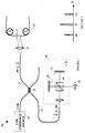
- Figure 1 is a block diagram of an apparatus according to the present invention for measuring the thickness of a film.
- Figure 2 illustrates the signal generated by the Michelson interferometer shown in Figure 1.
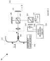
- Figure 3 is a block diagram of the preferred embodiment of a Michelson interferometer system according to the present invention.
- the light delivered to Michelson interferometer 18 includes two signals which result from the refection of the light incident on film 13 at the two surfaces of film 13. If film 13 has an index of refraction equal to ⁇ and a thickness of L, the two light signals will be separated in time by 2 ⁇ L/c, where c is the speed of light.
- the light incident on Michelson interferometer is split into two beams that traverse different paths by beam splitter 19. The first path is determined by the position of fixed mirror 20 and the second by moveable mirror 21. After traversing the different paths, the light is recombined by splitter 19 and directed to a photodiode 22 which measures the intensity of the light which varies with the position of mirror 21 due to the interference of the light.
- the envelop of the interference pattern as a function of the position, X, of mirror 21 is shown in Figure 2.
- This function has three peaks.
- the two smaller peaks result from the cases in which the paths differ by the delay between the first and second peaks. In one of these cases, the first peak interferes with the second peak.
- the remaining peak corresponds to the interference of the second peak in one arm of the Michelson interferometer with the first peak in the other arm.
- Lens 15 also provides a means for adjusting the light collection efficiency of the system to movements of the film being measured.
- "flutter" will be defined to be the motion of the film along the optical axis of lens 15. If the light from lens 15 is tightly focused; i.e., focused light has a high numerical aperture, then the collection efficiency will be very sensitive to flutter. In a tightly focused system, flutter causes the boundary of the film to move in and out of focus. When the boundary is out of focus, the light collected by lens 15 and reinjected into fiber 14 is substantially reduced. Hence, if the film is mounted so as to produce a significant amount of flutter, lens 15 preferably has a low numerical aperture.
- the accuracy with which the position of mirror 21 can be measured using conventional measuring and calibration techniques limits the accuracy of the measurement of the film thickness.
- the actuator that moves mirror 21 can be calibrated by using a reference coherent light source as the input to Michelson interferometer 118 and counting the resulting interference fringe pattern to calibrate the actuator.
- a reference coherent light source as the input to Michelson interferometer 118
- counting the resulting interference fringe pattern to calibrate the actuator.
- temperature, changes in mechanical linkages, and other factors limit the reliability of the calibration.
- FIG. 3 is a block diagram of the preferred embodiment of the Michelson interferometer system 70 used in the present invention.
- an element in Figure 3 that serves the same function as a corresponding element in Figure 1 is numbered with a number that differs by 100 from that of the number of the corresponding element shown in Figure 1.
- a reference light source 134 which is preferably a laser is added to the light reflected from the film with the aid of a coupler 145 that adds light from source 134 to the light from the film coupled through fiber 117.
- the light from the reference source gives rise to interference fringes at the reference light frequency.
- the intensity of light from these fringes goes through one maximum for every one half wavelength that mirror 121 moves.
- the reference wavelength is chosen to be sufficiently different from that of the light reflected from the film that the two signals may be separated with the aid of a beam splitter 131 and optical filters 138 and 139. Alternatively, a dichotic beam splitter may be used.
- the reference fringe pattern is detected by photodiode 133 which serves as a reference input to signal processing circuit 135.
- Signal processing circuit 135 samples the output of photodiode 122 utilizing the reference fringe pattern for timing. Since the reference fringe pattern effectively calibrates the distance X during the actual measurement, the above-mentioned problems with calibrations is overcome. Using a reference light signal for distance measurement allows an absolute distance calibration that is accurate to better than the wavelength of the reference light.
Landscapes
- Physics & Mathematics (AREA)
- General Physics & Mathematics (AREA)
- Length Measuring Devices By Optical Means (AREA)
- Instruments For Measurement Of Length By Optical Means (AREA)
Applications Claiming Priority (2)
| Application Number | Priority Date | Filing Date | Title |
|---|---|---|---|
| US304247 | 1989-01-31 | ||
| US08/304,247 US5473432A (en) | 1994-09-12 | 1994-09-12 | Apparatus for measuring the thickness of a moving film utilizing an adjustable numerical aperture lens |
Publications (2)
| Publication Number | Publication Date |
|---|---|
| EP0701103A2 true EP0701103A2 (de) | 1996-03-13 |
| EP0701103A3 EP0701103A3 (de) | 1997-05-21 |
Family
ID=23175697
Family Applications (1)
| Application Number | Title | Priority Date | Filing Date |
|---|---|---|---|
| EP95110817A Withdrawn EP0701103A3 (de) | 1994-09-12 | 1995-07-11 | Auf optischer Interferenz basierender Dickenmessapparat |
Country Status (3)
| Country | Link |
|---|---|
| US (1) | US5473432A (de) |
| EP (1) | EP0701103A3 (de) |
| JP (1) | JPH08101020A (de) |
Cited By (1)
| Publication number | Priority date | Publication date | Assignee | Title |
|---|---|---|---|---|
| RU2307318C1 (ru) * | 2005-12-19 | 2007-09-27 | Петр Витальевич Волков | Интерферометрическое измерительное устройство (варианты) |
Families Citing this family (23)
| Publication number | Priority date | Publication date | Assignee | Title |
|---|---|---|---|---|
| US5633712A (en) * | 1995-08-28 | 1997-05-27 | Hewlett-Packard Company | Method and apparatus for determining the thickness and index of refraction of a film using low coherence reflectometry and a reference surfaces |
| US5731876A (en) * | 1996-09-17 | 1998-03-24 | Hewlett-Packard Company | Method and apparatus for on-line determination of the thickness of a multilayer film using a partially reflecting roller and low coherence reflectometry |
| FR2765964A1 (fr) * | 1997-07-08 | 1999-01-15 | Bertin & Cie | Dispositif optique de mesure de distance avec une grande precision |
| US6034774A (en) * | 1998-06-26 | 2000-03-07 | Eastman Kodak Company | Method for determining the retardation of a material using non-coherent light interferometery |
| US6034772A (en) * | 1998-10-29 | 2000-03-07 | Eastman Kodak Company | Method for processing interferometric measurement data |
| US6067161A (en) * | 1998-10-29 | 2000-05-23 | Eastman Kodak Company | Apparatus for measuring material thickness profiles |
| US6038027A (en) * | 1998-10-29 | 2000-03-14 | Eastman Kodak Company | Method for measuring material thickness profiles |
| US6470294B1 (en) * | 1999-04-13 | 2002-10-22 | Qualitek-Vib, Inc. | System and method for the on-line measurement of glue application rate on a corrugator |
| CA2277855A1 (fr) | 1999-07-14 | 2001-01-14 | Solvision | Methode et systeme de mesure de la hauteur des billes de soudure d'un circuit imprime |
| CA2301822A1 (fr) * | 2000-03-24 | 2001-09-24 | 9071 9410 Quebec Inc. | Projection simultanee de plusieurs patrons avec acquisition simultanee pour l'inspection d'objets en trois dimensions |
| DE10047836A1 (de) * | 2000-09-27 | 2002-04-11 | Hosokawa Alpine Ag & Co | Verfahren und Vorrichtung zur Regelung des Foliendickenprofils in Folienblasanlagen |
| KR100409090B1 (ko) * | 2000-11-27 | 2003-12-11 | 케이맥(주) | 미세패턴 박막두께 측정장치. |
| US6937350B2 (en) * | 2001-06-29 | 2005-08-30 | Massachusetts Institute Of Technology | Apparatus and methods for optically monitoring thickness |
| KR20030016935A (ko) * | 2001-08-23 | 2003-03-03 | 광주과학기술원 | 광섬유 렌즈의 초점거리를 이용한 물질의 두께 측정장치및 그 방법 |
| US6806969B2 (en) * | 2001-10-19 | 2004-10-19 | Agilent Technologies, Inc. | Optical measurement for measuring a small space through a transparent surface |
| US6804008B1 (en) * | 2001-11-14 | 2004-10-12 | Fiber Optic Systems Technology, Inc. | Fiber optic sensing instrument and system with fiber of adjustable optical path length and method of using it |
| US6870975B1 (en) | 2001-11-14 | 2005-03-22 | Fiber Optic Systems Technology, Inc. | Fiber optic sensor usable over wide range of gage lengths |
| US7116429B1 (en) * | 2003-01-18 | 2006-10-03 | Walecki Wojciech J | Determining thickness of slabs of materials by inventors |
| EP3150958A1 (de) * | 2015-10-02 | 2017-04-05 | Nederlandse Organisatie voor toegepast- natuurwetenschappelijk onderzoek TNO | Optischer dickenmessvorrichtung und verfahren |
| CN107167085B (zh) * | 2017-04-25 | 2019-09-27 | 哈尔滨工程大学 | 一种共光路自校准薄膜厚度测量装置及测量方法 |
| CN109959342B (zh) * | 2017-12-26 | 2021-04-13 | 长春长光华大智造测序设备有限公司 | 物镜数值孔径的检测方法及装置 |
| CN109631783A (zh) * | 2019-01-22 | 2019-04-16 | 淮阴师范学院 | 透镜组轴上镜面间距的低相干光干涉测量装置及方法 |
| RU2709600C1 (ru) * | 2019-05-15 | 2019-12-18 | Федеральное государственное бюджетное учреждение науки Научно-технологический центр уникального приборостроения Российской академии наук (НТЦ УП РАН) | Интерферометр Майкельсона для определения показателя преломления поверхностных плазмон-поляритонов терагерцевого диапазона |
Citations (1)
| Publication number | Priority date | Publication date | Assignee | Title |
|---|---|---|---|---|
| US3319515A (en) | 1963-08-27 | 1967-05-16 | Du Pont | Interferometric optical phase discrimination apparatus |
Family Cites Families (3)
| Publication number | Priority date | Publication date | Assignee | Title |
|---|---|---|---|---|
| JPS61140806A (ja) * | 1984-12-14 | 1986-06-27 | Jeol Ltd | 膜厚測定方法 |
| EP0650030B1 (de) * | 1989-09-25 | 1999-05-12 | Mitsubishi Denki Kabushiki Kaisha | Apparat und Verfahren für die Ausmessung von dünnen mehrschichtigen Lagen |
| US5341205A (en) * | 1991-01-15 | 1994-08-23 | The United States Of America As Represented By The Secretary Of The Navy | Method for characterization of optical waveguide devices using partial coherence interferometry |
-
1994
- 1994-09-12 US US08/304,247 patent/US5473432A/en not_active Expired - Fee Related
-
1995
- 1995-07-11 EP EP95110817A patent/EP0701103A3/de not_active Withdrawn
- 1995-08-29 JP JP7245354A patent/JPH08101020A/ja active Pending
Patent Citations (1)
| Publication number | Priority date | Publication date | Assignee | Title |
|---|---|---|---|---|
| US3319515A (en) | 1963-08-27 | 1967-05-16 | Du Pont | Interferometric optical phase discrimination apparatus |
Cited By (1)
| Publication number | Priority date | Publication date | Assignee | Title |
|---|---|---|---|---|
| RU2307318C1 (ru) * | 2005-12-19 | 2007-09-27 | Петр Витальевич Волков | Интерферометрическое измерительное устройство (варианты) |
Also Published As
| Publication number | Publication date |
|---|---|
| EP0701103A3 (de) | 1997-05-21 |
| US5473432A (en) | 1995-12-05 |
| JPH08101020A (ja) | 1996-04-16 |
Similar Documents
| Publication | Publication Date | Title |
|---|---|---|
| US5473432A (en) | Apparatus for measuring the thickness of a moving film utilizing an adjustable numerical aperture lens | |
| US5610716A (en) | Method and apparatus for measuring film thickness utilizing the slope of the phase of the Fourier transform of an autocorrelator signal | |
| US5633712A (en) | Method and apparatus for determining the thickness and index of refraction of a film using low coherence reflectometry and a reference surfaces | |
| CN109791040B (zh) | 用于借助彩色共焦传感器进行光学表面测量的方法和装置 | |
| GB2144537A (en) | Profile measuring instrument | |
| CN101849158A (zh) | 光学传感器装置 | |
| US5642196A (en) | Method and apparatus for measuring the thickness of a film using low coherence reflectometry | |
| CN109163662A (zh) | 基于波长扫描的光谱共焦位移测量方法及装置 | |
| WO2013091584A1 (zh) | 一种检测基质内缺陷的方法及装置 | |
| WO2013084557A1 (ja) | 形状測定装置 | |
| EP0760459B1 (de) | System zum Messen der Dicke und des Brechungsindexes eines Films | |
| US20070146724A1 (en) | Vibration-resistant interferometer apparatus | |
| CN208721004U (zh) | 基于波长扫描的光谱共焦位移测量装置 | |
| JP2002296018A (ja) | 3次元形状計測装置 | |
| JP2005106706A (ja) | 屈折率及び厚さの測定装置ならびに測定方法 | |
| JPS6334963B2 (de) | ||
| JP3325648B2 (ja) | 変位測定装置 | |
| JPH0469508A (ja) | 非接触式形状測定装置及び形状測定法 | |
| JP2003148909A (ja) | 干渉装置 | |
| CN118999385A (zh) | 一种精密离心机转臂动态半径变化测量装置及方法 | |
| JP2003518254A (ja) | 移動構成要素上の任意ポイントのタイムマーカを発生するための方法及び該方法を実施するための光学式トリガー装置 | |
| CN117190870A (zh) | 一种结合单色光和白光的干涉测量装置及方法 | |
| JP2989995B2 (ja) | 位置合せ装置 | |
| Holly | Lateral Interferometry-Its Characteristics, Technology and Applications | |
| JP2005274428A (ja) | 厚さ測定装置ならびに厚さ測定方法 |
Legal Events
| Date | Code | Title | Description |
|---|---|---|---|
| PUAI | Public reference made under article 153(3) epc to a published international application that has entered the european phase |
Free format text: ORIGINAL CODE: 0009012 |
|
| AK | Designated contracting states |
Kind code of ref document: A2 Designated state(s): DE FR GB |
|
| PUAL | Search report despatched |
Free format text: ORIGINAL CODE: 0009013 |
|
| AK | Designated contracting states |
Kind code of ref document: A3 Designated state(s): DE FR GB |
|
| 17P | Request for examination filed |
Effective date: 19970916 |
|
| 17Q | First examination report despatched |
Effective date: 19990512 |
|
| GRAG | Despatch of communication of intention to grant |
Free format text: ORIGINAL CODE: EPIDOS AGRA |
|
| STAA | Information on the status of an ep patent application or granted ep patent |
Free format text: STATUS: THE APPLICATION HAS BEEN WITHDRAWN |
|
| 18W | Application withdrawn |
Withdrawal date: 20000322 |