EP0701111A2 - Hakenprüfvorrichtung - Google Patents
Hakenprüfvorrichtung Download PDFInfo
- Publication number
- EP0701111A2 EP0701111A2 EP95202214A EP95202214A EP0701111A2 EP 0701111 A2 EP0701111 A2 EP 0701111A2 EP 95202214 A EP95202214 A EP 95202214A EP 95202214 A EP95202214 A EP 95202214A EP 0701111 A2 EP0701111 A2 EP 0701111A2
- Authority
- EP
- European Patent Office
- Prior art keywords
- wipper
- testing device
- pontoon
- vessel
- hook
- Prior art date
- Legal status (The legal status is an assumption and is not a legal conclusion. Google has not performed a legal analysis and makes no representation as to the accuracy of the status listed.)
- Withdrawn
Links
- 238000012360 testing method Methods 0.000 title claims abstract description 36
- 230000000694 effects Effects 0.000 description 4
- 230000006378 damage Effects 0.000 description 3
- 208000027418 Wounds and injury Diseases 0.000 description 2
- 208000014674 injury Diseases 0.000 description 2
- 230000002452 interceptive effect Effects 0.000 description 2
- 238000012986 modification Methods 0.000 description 2
- 230000004048 modification Effects 0.000 description 2
- 238000001514 detection method Methods 0.000 description 1
- 238000006073 displacement reaction Methods 0.000 description 1
Images


Classifications
-
- G—PHYSICS
- G01—MEASURING; TESTING
- G01L—MEASURING FORCE, STRESS, TORQUE, WORK, MECHANICAL POWER, MECHANICAL EFFICIENCY, OR FLUID PRESSURE
- G01L5/00—Apparatus for, or methods of, measuring force, work, mechanical power, or torque, specially adapted for specific purposes
- G01L5/0028—Force sensors associated with force applying means
- G01L5/0033—Force sensors associated with force applying means applying a pulling force
Definitions
- the subject invention relates to a testing device for wipper hooks on vessels.
- Wipper hooks are used on vessels wherein during sailing a load or person has to be moved from one vessel to an adjacent vessel.
- a line is provided extending from an eye provided on a mast on one vessel to a corresponding eye on another mast of the other vessel.
- testing is not only realized in the direction perpendicular to the board of the vessel, but also in the direction with an angle thereto such a safety area had to be relatively large.
- a further problem encountered was that during testing the testing device had to be displaced all along the side of the vessel. This means that the safety area had to be constantly changed.
- the present invention provides a testing device which is particularly useful for testing wipper hooks.
- the testing device is specifically designed to test these wipper hooks without interfering any other activities on the vessel and without the danger of injury or daage to persons and articles on the quay where the vessel is moored.
- the testing device for wipper hooks on vessels comprising a vessel, such as a pontoon to be positioned against the vessel on which the wipper hook is provided, said pontoon being provided with traction means connected to a line system, arranged to engage the wipper hook to be tested, wherein the traction means are provided with means to determine the traction force exerted on the wipper hook.
- the invention aims to provide a testing device which can simply be adapted to these several heights.
- the traction means comprise height adjustable engagement means having line receiving means.
- this sleeve is preferably rotatable with regard to the post such that it will automatically direct itself to the wipper hook to be tested.
- These height adjustable engagement means preferably comprise a sleeve slidably arranged on a vertical post.
- a further advantage of the invention is the possibility to accurately measure the force exerted on the wipper hook. To that end a load cell is placed in the line connecting the traction means and the wipper hook.
- the traction force on the wipper hook is preferably provided by a hydraulic ram having guiding means for the line.
- the pontoon can easily be displaced alongside the vessel of which the wipper hooks have to be tested by the provision of winch means.
- the cables of the winches are connected to the vessel and by paying or tensioning the cables the vessel can be moved alongside the vessel.
- ballast means are provided on the pontoon according to the invention.
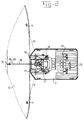
- the testing device is generally referred to by 1. It comprises a vessel or pontoon 2. To pontoon 2 a vertical mast 3 is connected on which a sleeve 4 can be slid in upward and downward direction and which can also rotate around the mast. The vertical movement is controlled by a winch 5 which is connected to sleeve 4 through cables 6. Winches 7 and 8 are provided to control the relative position of the pontoon to the vessel. Cables 9 and 10 are connected to these winches on the one hand and connected to bollards 11 on the vessel 12 to be tested on the other hand. On this vessel 12 several masts 13 are provided with eyes 14. The integrity of eyes 14 and masts 13 (wipper hooks) has to be tested according- to standardized specifications.
- Pontoon 2 is furthermore provided with fender blocks 15 and 16.
- a control cabin 17 has all the necessary equipment to control both the movement of the pontoon as well as the detection and magnitude of the force exerted by the traction means.
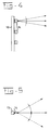
- traction means comprise a chain 18 on the one hand connected through a chain stopper with sleeve 4 and on the other hand having a hook 19 to engage an eye 14.
- a load cell 20 is accommodated to obtain the most accurate information about the force exerted near hook 19.
- the related data are transferred through line 21.
- Sleeve 14 comprises a hydraulic ram 22 having a pulley 23 on its piston part. Another pulley 24 is provided to guide chain 18. By outward displacement of ram 22 the length of the chain 18 in horizontal direction is shortened.
- ballast weights 25 are provided on the deck of pontoon 2. Together with crane 26 these ballast weights could be used for testing davits on the vessel to be tested.
- the device described above functions as follows.
- the pontoon 2 is moored against the vessel 12 and accurately positioned with regard to eye 14 to be tested by man penetrationng winches 7 and 8 and thus cables 9,10. Both winches 7 and 8 are hydraulically operated in a so called tensioning system. After the correct position of the pontoon relative to the eyelet to be tested is obtained the correct height of chain 18 is adjusted.
- the minimum value is about 4 tonnes whilst normally the maximum is about 20 tonnes.
Landscapes
- Chemical & Material Sciences (AREA)
- Analytical Chemistry (AREA)
- Physics & Mathematics (AREA)
- General Physics & Mathematics (AREA)
- Investigating Strength Of Materials By Application Of Mechanical Stress (AREA)
Applications Claiming Priority (2)
| Application Number | Priority Date | Filing Date | Title |
|---|---|---|---|
| US290500 | 1981-08-06 | ||
| US08/290,500 US5501108A (en) | 1994-08-15 | 1994-08-15 | Testing device for wipper hooks |
Publications (2)
| Publication Number | Publication Date |
|---|---|
| EP0701111A2 true EP0701111A2 (de) | 1996-03-13 |
| EP0701111A3 EP0701111A3 (de) | 1997-01-29 |
Family
ID=23116287
Family Applications (1)
| Application Number | Title | Priority Date | Filing Date |
|---|---|---|---|
| EP95202214A Withdrawn EP0701111A3 (de) | 1994-08-15 | 1995-08-15 | Hakenprüfvorrichtung |
Country Status (2)
| Country | Link |
|---|---|
| US (1) | US5501108A (de) |
| EP (1) | EP0701111A3 (de) |
Families Citing this family (1)
| Publication number | Priority date | Publication date | Assignee | Title |
|---|---|---|---|---|
| US6098470A (en) * | 1998-11-11 | 2000-08-08 | Alexander/Ryan Marine & Safety Co. | Method and apparatus for testing hook release |
Family Cites Families (12)
| Publication number | Priority date | Publication date | Assignee | Title |
|---|---|---|---|---|
| US1136511A (en) * | 1913-11-17 | 1915-04-20 | Daimler Motoren | Tractive-force-measuring appliance. |
| US1433067A (en) * | 1920-01-23 | 1922-10-24 | Burr Company | Dynamometer |
| US2079021A (en) * | 1936-03-19 | 1937-05-04 | John C Malcolm | Indicating mechanism for trawling |
| US2108433A (en) * | 1937-01-26 | 1938-02-15 | Dravo Corp | Fleet testing dynamometer |
| CH358950A (de) * | 1958-01-18 | 1961-12-15 | Inventio Ag | Vorrichtung zur Bildung eines Belastungsgewichtes für Belastungsprüfungen, z.B. an Aufzügen, Kränen, Seilbahnen |
| US3110176A (en) * | 1960-07-26 | 1963-11-12 | Melvin E Dreier | Testing device for tractor pulling power |
| GB1226440A (de) * | 1968-12-13 | 1971-03-31 | ||
| US3661090A (en) * | 1970-01-09 | 1972-05-09 | Nat Defence Canada | Lateral load transfer |
| US3624783A (en) * | 1970-06-12 | 1971-11-30 | Santa Fe Int Corp | Motion control system |
| US3720400A (en) * | 1970-11-25 | 1973-03-13 | Garrett Corp | Cable drum gear apparatus |
| US4106335A (en) * | 1976-12-27 | 1978-08-15 | Santa Fe International Corporation | Sea sled tow line vector system |
| US4755947A (en) * | 1986-03-03 | 1988-07-05 | Parmac, Inc. | Monitor for and method of deploying anchor lines for off shore platforms |
-
1994
- 1994-08-15 US US08/290,500 patent/US5501108A/en not_active Expired - Fee Related
-
1995
- 1995-08-15 EP EP95202214A patent/EP0701111A3/de not_active Withdrawn
Non-Patent Citations (1)
| Title |
|---|
| None |
Also Published As
| Publication number | Publication date |
|---|---|
| EP0701111A3 (de) | 1997-01-29 |
| US5501108A (en) | 1996-03-26 |
Similar Documents
| Publication | Publication Date | Title |
|---|---|---|
| US3967572A (en) | Anchoring system and chain stopper therefor | |
| EP2729353B1 (de) | Spannverfahren für ankertau | |
| USRE36971E (en) | Method of determining and analyzing a ship's weight | |
| EP3155393B1 (de) | Pollertestsystem | |
| US9630814B2 (en) | System and apparatus for motion compensation and anti-pendulation | |
| US4632622A (en) | Marine cargo transfer device | |
| US11505401B1 (en) | Method and apparatus for storage and transportation of cargo | |
| US6044787A (en) | Ship and a method adapted to generate tensile stresses in a pull line extended between the ships and an object to which a pull is to be applied | |
| GB2502993A (en) | Dockside bollard testing | |
| US5501108A (en) | Testing device for wipper hooks | |
| US3428194A (en) | Ship barge handling cranes and beams | |
| US4246860A (en) | Method for anchor retrieval | |
| CN214001962U (zh) | 一种船上救生钟铠装缆挂缆辅助平台 | |
| CN110356980B (zh) | 新型平台整体吊装下水方法 | |
| NO171446B (no) | Fremgangsmaate og anordning for loefting av en tung gjenstand fra en posisjon paa et flytende fartoey | |
| EP0145688A2 (de) | Vorrichtung an Bord von Schiffen zum Zuwasserlassen oder Einholen von Bojen oder sonstigen schwimmenden Stationen | |
| CN85104776A (zh) | 系船装置 | |
| KR102622812B1 (ko) | 계류용 후크장치 | |
| CN120364061A (zh) | 一种具有自航系统的转载驳船的系泊系统 | |
| RU2072938C1 (ru) | Устройство для подъема затонувшего объекта | |
| US11215541B1 (en) | In-situ bollard tester | |
| SU998314A1 (ru) | Способ перемещени груза двум кранами | |
| House | Lifting Gear | |
| SU927633A1 (ru) | Устройство дл опускани грузов под воду | |
| CN117923294A (zh) | 一种大型坐底式海洋装备近岸布放方法 |
Legal Events
| Date | Code | Title | Description |
|---|---|---|---|
| PUAI | Public reference made under article 153(3) epc to a published international application that has entered the european phase |
Free format text: ORIGINAL CODE: 0009012 |
|
| AK | Designated contracting states |
Kind code of ref document: A2 Designated state(s): BE DE DK ES FR GB IT SE |
|
| PUAL | Search report despatched |
Free format text: ORIGINAL CODE: 0009013 |
|
| AK | Designated contracting states |
Kind code of ref document: A3 Designated state(s): BE DE DK ES FR GB IT SE |
|
| 17P | Request for examination filed |
Effective date: 19970704 |
|
| STAA | Information on the status of an ep patent application or granted ep patent |
Free format text: STATUS: THE APPLICATION IS DEEMED TO BE WITHDRAWN |
|
| 18D | Application deemed to be withdrawn |
Effective date: 20000228 |