EP0701138A2 - Méthode d'analyse de signaux à l'aide d'histograms - Google Patents
Méthode d'analyse de signaux à l'aide d'histograms Download PDFInfo
- Publication number
- EP0701138A2 EP0701138A2 EP95305879A EP95305879A EP0701138A2 EP 0701138 A2 EP0701138 A2 EP 0701138A2 EP 95305879 A EP95305879 A EP 95305879A EP 95305879 A EP95305879 A EP 95305879A EP 0701138 A2 EP0701138 A2 EP 0701138A2
- Authority
- EP
- European Patent Office
- Prior art keywords
- level
- signal
- amplitude
- time
- input signal
- Prior art date
- Legal status (The legal status is an assumption and is not a legal conclusion. Google has not performed a legal analysis and makes no representation as to the accuracy of the status listed.)
- Granted
Links
- 238000004458 analytical method Methods 0.000 title claims abstract description 19
- 238000000034 method Methods 0.000 title claims abstract description 10
- 230000035945 sensitivity Effects 0.000 description 7
- 230000003750 conditioning effect Effects 0.000 description 5
- 230000001960 triggered effect Effects 0.000 description 3
- 125000004122 cyclic group Chemical group 0.000 description 2
- 238000010586 diagram Methods 0.000 description 2
- 230000008014 freezing Effects 0.000 description 2
- 238000007710 freezing Methods 0.000 description 2
- 238000012986 modification Methods 0.000 description 2
- 230000004048 modification Effects 0.000 description 2
- 230000003252 repetitive effect Effects 0.000 description 2
- 230000007704 transition Effects 0.000 description 2
- 238000007796 conventional method Methods 0.000 description 1
- 238000001514 detection method Methods 0.000 description 1
- 230000009977 dual effect Effects 0.000 description 1
- 230000006870 function Effects 0.000 description 1
- 239000004973 liquid crystal related substance Substances 0.000 description 1
Images


Classifications
-
- G—PHYSICS
- G01—MEASURING; TESTING
- G01R—MEASURING ELECTRIC VARIABLES; MEASURING MAGNETIC VARIABLES
- G01R13/00—Arrangements for displaying electric variables or waveforms
- G01R13/20—Cathode-ray oscilloscopes
- G01R13/22—Circuits therefor
- G01R13/34—Circuits for representing a single waveform by sampling, e.g. for very high frequencies
- G01R13/345—Circuits for representing a single waveform by sampling, e.g. for very high frequencies for displaying sampled signals by using digital processors by intermediate A.D. and D.A. convertors (control circuits for CRT indicators)
-
- G—PHYSICS
- G01—MEASURING; TESTING
- G01R—MEASURING ELECTRIC VARIABLES; MEASURING MAGNETIC VARIABLES
- G01R13/00—Arrangements for displaying electric variables or waveforms
- G01R13/20—Cathode-ray oscilloscopes
- G01R13/22—Circuits therefor
- G01R13/24—Time-base deflection circuits
-
- G—PHYSICS
- G01—MEASURING; TESTING
- G01R—MEASURING ELECTRIC VARIABLES; MEASURING MAGNETIC VARIABLES
- G01R13/00—Arrangements for displaying electric variables or waveforms
- G01R13/20—Cathode-ray oscilloscopes
- G01R13/22—Circuits therefor
- G01R13/32—Circuits for displaying non-recurrent functions such as transients; Circuits for triggering; Circuits for synchronisation; Circuits for time-base expansion
Definitions
- This invention relates generally to scaling and triggering arrangements for oscilloscopes, and in particular to a system for analyzing input signals using amplitude and time histograms to establish vertical sensitivity, time base setting, and triggering levels for oscilloscopes to provide stable, viewable displays.
- Typical digital oscilloscopes rely on the user to manually adjust vertical and horizontal scale factors, and to adjust the triggering level to achieve stable triggering. More sophisticated oscilloscopes utilize digital comparators to detect peak amplitude values of input signals automatically to establish vertical sensitivity and level-crossing trigger detection automatically to establish a time base setting as well as a triggered display.
- a method of achieving automatic signal scaling and stable triggering for digital storage oscilloscopes employs amplitude and time histograms to analyze an incoming signal.
- An untriggered, or free-running, incoming signal is converted to digital representations, or samples, by an analog-to-digital converter (ADC) in the conventional manner and processed by an acquisition processor.
- ADC analog-to-digital converter
- the digitized samples are first analyzed to form an amplitude histogram by counting the number of occurrences of each discrete amplitude value.
- the minimum (MIN) and maximum (MAX) signal excursions may be quickly determined by this method.
- the MIN and MAX amplitude values may then be used to adjust the vertical sensitivity of the input amplifier to result in an on-screen displayed waveform of an appropriately-scaled (on the vertical axis) reconstructed signal.
- lower and upper triggering levels may be established within the peak-to-peak signal amplitude to permit level-crossing trigger signals to be generated by an associated trigger circuit.
- the digitized samples are analyzed to form a time histogram by counting the number of samples that occur over each of a number of signal periods for cyclic waveforms such as sine or square waves, or intervals for complex waveforms, using level-crossing signal analysis to determine the signal intervals. That is, a signal interval (which for purposes of this discussion includes signal periods) is detected when the signal passes through a first level, then a second level, and then back to the first level, such as a low-high-low sequence or a high-low-high sequence. These occurrences are ordered in the form of lengths of intervals on a time histogram to determine which interval occurs most often. The interval thus determined as being the predominant interval of the input signal may then be used to adjust the horizontal time base to result in an on-screen displayed waveform of a predetermined or user-selected number of cycles of the signal.
- Signal conditioning circuit 12 may include conventional attenuators and gain-switching preamplifiers to adjust the input signal amplitude to a suitable level.
- the preamplified electrical signal is then applied to a track-and-hold/analog-to-digital converter (ADC) 14, which converts instantaneous values of the input signal to digitized samples at a rate determined by an acquisition clock 16.
- a replica of the input signal is applied from the signal conditioning circuit 12 to a trigger circuit 18, which issues a valid trigger signal upon the occurrence of a predetermined event (to be described later).
- the digitized samples produced by ADC 14 are continuously written into addresses in an acquisition memory 20 until acquisition is halted by a valid trigger event, freezing the memory contents. Thereafter, the digitized samples may be processed as digital data by a system microprocessor or CPU 22 and transferred to a system memory 24, from which such digital data may reconstructed for display.
- display device 42 may be any of a number of well-known available devices having a viewing screen suitable for displaying signal waveforms and textual information, such as a cathode-ray tube or a flat-panel liquid-crystal display.
- CPU 22 analyzes the waveform from the digitized samples that are being written into the acquisition memory 20 and subsequently provides information for automatically scaling the waveform by adjusting the vertical sensitivity of amplifiers within signal conditioning circuit 12, and by adjusting the time base 38 to display a predetermined or user-selected number of cycles of waveform. Information is also provided to establish stable triggering.
- a stream of digitized samples from ADC 14 is continuously written into acquisition memory 20, as mentioned earlier.
- CPU 22 analyzes the samples to develop an amplitude histogram by counting the number of occurrences of each discrete amplitude value over some finite time interval, such as one trace, or display screen width of information. That is, suppose one trace is made up of 500 digitized samples. Each sample value is used as an index in the amplitude histogram.
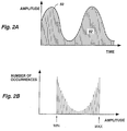
- Fig. 2A which shows a representation of an analog waveform 50, which for purposes of discussion is a sine wave.
- Vertical lines 52 represent the discrete amplitude values of instantaneous samples taken along the time axis of the waveform.
- CPU 22 determines the number of times over one trace that each discrete amplitude value occurs, and internally constructs an amplitude histogram as shown in Fig. 2B.
- the minimum (MIN) and maximum (MAX) amplitude values of the waveform are quickly discerned, and the two values are stored.
- the minimum and maximum amplitude values are used to determine whether or not attenuation or gain settings need to be adjusted, and the amount of adjustment needed.
- CPU 22 may then apply vertical sensitivity information, such as attenuation and vertical gain, to signal conditioning circuit 12 to appropriately scale the amplitude of the input signal to a viewable level on display device 42.
- the MIN and MAX values may be displayed to a user, who can then manually adjust the vertical sensitivity controls and settings from the front panel in the conventional manner.
- the histogram analysis and vertical gain adjustments may be repeated until optimal signal peak-to-peak amplitude (the distance between MIN and MAX in the histogram) is attained.
- the minimum and maximum values are used to calculate two levels, e.g., at the 15% and 85% points, on the waveform for later use in making time histogram calculations and for establishing level-crossing trigger events to be generated by trigger circuit 22.
- the amplitude histogram form of analysis is based on statistics, and therefore it is necessary that the waveform traces being analyzed not be triggered during this time. Accordingly, trigger circuit 18 is disabled during the signal analysis.
- the time intervals are signal intervals or periods as measured beginning at both the low and high levels. The time is measured between a starting point at each level to an end point that is the same point on the waveform as the starting point to determine the time for one interval of signal. That is, a signal interval is detected when the signal passes through a first level, then a second level, and then back to the first level, such as a low-high-low sequence or a high-low-high sequence. For example, the length of each interval of signal in Fig.
- the interval determined as being the predominant interval of the input signal may then be used to manually or automatically adjust the horizontal time base to result in an on-screen displayed waveform of a predetermined or user-selected number of cycles of the signal.
- the user wishes to view two cycles of a 5-megahertz signal. Since each cycle of signal has a period of 0.2 microseconds, the length of displayed waveform over ten horizontal divisions will be adjusted to 0.4 microseconds, or 40 nanoseconds per division.
- the time base setting may therefore be quickly calculated and selected by the microprocessor or CPU 22, or may displayed to a user who can then manually adjust the time base controls.
- CPU 22 determines either a low trigger level or a high trigger level from intervals which best match the signal period. The selected low or high trigger level is then applied to trigger circuit 12, and triggered operation is commenced. It should be noted that if neither the low level nor high level match a predominant signal interval, both a low and a high trigger level may be selected for use at the same time, providing a two-level triggering mode to obtain a stable display.
- FIG. 4A Another example of time histogram signal analysis is shown in Figs. 4A and 4B.
- Fig. 4A a more complex waveform 50 is shown along with low and high levels 54, 56 determined from an amplitude histogram analysis.
- the intervals T0, T2 and T4 are the low-high-low transition intervals
- the intervals T1, T3 and T5 are the high-low-high transition intervals.
- the interval represented by T1, T2, T3, and T5 is the predominant interval, and is used to determine the time base setting. Also, since this interval value recurs most often, level 56, in this instance, is selected as the trigger level and applied to trigger circuit 18.
- an amplitude histogram analysis is first used to determine minimum and maximum amplitude levels of the signal, and then a time histogram analysis is used to determine the period, or interval of the input signal. From these two analyses, vertical gain and time base adjustments or settings may be made either manually or automatically using conventional techniques, and a triggering level (or dual triggering level) established to provide a stable, usable display.
Landscapes
- Physics & Mathematics (AREA)
- General Physics & Mathematics (AREA)
- Measurement Of Current Or Voltage (AREA)
- Controls And Circuits For Display Device (AREA)
- Analogue/Digital Conversion (AREA)
Applications Claiming Priority (2)
| Application Number | Priority Date | Filing Date | Title |
|---|---|---|---|
| US304909 | 1994-09-12 | ||
| US08/304,909 US5495168A (en) | 1994-09-12 | 1994-09-12 | Method of signal analysis employing histograms to establish stable, scaled displays in oscilloscopes |
Publications (3)
| Publication Number | Publication Date |
|---|---|
| EP0701138A2 true EP0701138A2 (fr) | 1996-03-13 |
| EP0701138A3 EP0701138A3 (fr) | 1997-04-16 |
| EP0701138B1 EP0701138B1 (fr) | 2002-03-20 |
Family
ID=23178497
Family Applications (1)
| Application Number | Title | Priority Date | Filing Date |
|---|---|---|---|
| EP95305879A Expired - Lifetime EP0701138B1 (fr) | 1994-09-12 | 1995-08-22 | Méthode d'analyse de signaux à l'aide d'histograms |
Country Status (4)
| Country | Link |
|---|---|
| US (1) | US5495168A (fr) |
| EP (1) | EP0701138B1 (fr) |
| JP (1) | JP2640224B2 (fr) |
| DE (1) | DE69525888T2 (fr) |
Cited By (10)
| Publication number | Priority date | Publication date | Assignee | Title |
|---|---|---|---|---|
| EP0898713A4 (fr) * | 1996-04-10 | 1999-08-11 | Lecroy Corp | Complexe de mesure d'enregistrement optique |
| EP1152248A3 (fr) * | 1996-04-10 | 2002-01-23 | Lecroy Corporation | Procédé de mesure d'enrégistrement optique |
| US6553270B1 (en) * | 1999-06-30 | 2003-04-22 | Kimberly-Clark Worldwide, Inc. | Proactive control of a process after the beginning of a destabilizing event |
| WO2004030023A3 (fr) * | 2002-09-25 | 2004-06-17 | Ionalytics Corp | Procede de triage destine a une optimisation automatisee d'elements electroniques d'accord lc d'un generateur de formes d'ondes asymetriques |
| EP1505397A1 (fr) * | 2003-07-11 | 2005-02-09 | Ionalytics Corporation | Optimisation automatisée de l' accord du circuit résonant LC d' un générateur de formes d' ondes asymétriques. |
| US7084394B2 (en) | 2002-09-25 | 2006-08-01 | Ionalytics Corporation | FAIMS apparatus and method for separating ions |
| US7225096B2 (en) | 2002-09-25 | 2007-05-29 | Thermo Finnigan Llc | Method of controlling and correcting an asymmetric waveform |
| WO2014072271A1 (fr) * | 2012-11-12 | 2014-05-15 | Rohde & Schwarz Gmbh & Co. Kg | Procédé et dispositif de détermination d'une condition de déclenchement d'un événement de signalisation rare |
| WO2015011098A1 (fr) * | 2013-07-24 | 2015-01-29 | Commissariat à l'énergie atomique et aux énergies alternatives | Procede et dispositif de mesure du module d'une impedance electrique |
| CN104535815A (zh) * | 2014-12-16 | 2015-04-22 | 北京航天测控技术有限公司 | 一种全数字的两级组合触发信号提取方法 |
Families Citing this family (42)
| Publication number | Priority date | Publication date | Assignee | Title |
|---|---|---|---|---|
| US6263290B1 (en) | 1995-02-22 | 2001-07-17 | Michael K. Williams | Process and machine for signal waveform analysis |
| US5764524A (en) * | 1996-02-12 | 1998-06-09 | Snap-On Technologies, Inc. | Method and apparatus for detection of missing pulses from a repetitive pulse train |
| US5941926A (en) * | 1996-04-10 | 1999-08-24 | Snap-On Technologies, Inc. | Engine analyzer with cylinder triggering of oscilloscope display having fixed-time sweep |
| US6151010A (en) * | 1996-05-24 | 2000-11-21 | Lecroy, S.A. | Digital oscilloscope display and method therefor |
| DE19649525A1 (de) * | 1996-11-29 | 1998-06-04 | Hermann Electronic Gmbh | Verfahren und Einrichtung zur datenreduzierten Signalabtastung, -speicherung und -darstellung eines analogen elektrischen Eingangssignals |
| US6571185B1 (en) | 1999-04-20 | 2003-05-27 | Tektronix, Inc. | Continually responsive and anticipating automatic setup function for a digital oscilloscope |
| US6621767B1 (en) * | 1999-07-14 | 2003-09-16 | Guide Technology, Inc. | Time interval analyzer having real time counter |
| US6571186B1 (en) * | 1999-09-14 | 2003-05-27 | Textronix, Inc. | Method of waveform time stamping for minimizing digitization artifacts in time interval distribution measurements |
| US6418386B1 (en) * | 1999-12-06 | 2002-07-09 | Koninklijke Philips Electronics N.V. | High and low voltage measurement in waveform analysis |
| US6993578B1 (en) * | 1999-12-08 | 2006-01-31 | Agilent Technologies, Inc. | Method and system for managing performance data about a network |
| CA2402631C (fr) * | 2000-03-09 | 2011-10-11 | Smartsignal Corporation | Operateur generalise de similarite angulaire lenticulaire |
| US6957172B2 (en) | 2000-03-09 | 2005-10-18 | Smartsignal Corporation | Complex signal decomposition and modeling |
| US6525525B1 (en) | 2000-05-02 | 2003-02-25 | Tektronix, Inc. | Oscilloscope with simplified setup procedure, and procedure for setting up oscilloscope |
| US6704445B1 (en) * | 2000-09-08 | 2004-03-09 | Avid Technology, Inc. | Spike tolerant histograms |
| US6556939B1 (en) | 2000-11-22 | 2003-04-29 | Smartsignal Corporation | Inferential signal generator for instrumented equipment and processes |
| US6975962B2 (en) * | 2001-06-11 | 2005-12-13 | Smartsignal Corporation | Residual signal alert generation for condition monitoring using approximated SPRT distribution |
| US20030076337A1 (en) * | 2001-10-19 | 2003-04-24 | Chenjing Fernando | Scaling method and apparatus for displaying signals |
| US20060256137A1 (en) * | 2001-10-19 | 2006-11-16 | Chenjing Fernando | Scaling method and apparatus for displaying signals |
| US6847905B2 (en) * | 2002-02-12 | 2005-01-25 | Tektronix, Inc. | Architecture providing increased information display for long acquisitions or constrained memory bandwidth |
| US6934646B2 (en) * | 2002-10-21 | 2005-08-23 | Agilent Technologies, Inc. | Waveform complexity detector |
| US7155355B2 (en) * | 2003-02-25 | 2006-12-26 | Tektronix, Inc. | Method of constraints control for oscilloscope vertical subsection and display parameters |
| US6915218B2 (en) * | 2003-02-25 | 2005-07-05 | Tektronix, Inc. | Method of constraints control for oscilloscope timebase subsection and display parameters |
| US7818131B2 (en) * | 2005-06-17 | 2010-10-19 | Venture Gain, L.L.C. | Non-parametric modeling apparatus and method for classification, especially of activity state |
| CN101365378A (zh) | 2005-11-29 | 2009-02-11 | 风险获利有限公司 | 根据残差监测人体健康 |
| US8275577B2 (en) | 2006-09-19 | 2012-09-25 | Smartsignal Corporation | Kernel-based method for detecting boiler tube leaks |
| US8311774B2 (en) * | 2006-12-15 | 2012-11-13 | Smartsignal Corporation | Robust distance measures for on-line monitoring |
| US8024140B2 (en) * | 2007-08-23 | 2011-09-20 | Amherst Systems Associates, Inc. | Waveform anomoly detection and notification systems and methods |
| US8094034B2 (en) | 2007-09-18 | 2012-01-10 | Georgia Tech Research Corporation | Detecting actuation of electrical devices using electrical noise over a power line |
| TWI346784B (en) * | 2007-10-23 | 2011-08-11 | Pegatron Corp | Automiatic jitter measurement method |
| US9766277B2 (en) | 2009-09-25 | 2017-09-19 | Belkin International, Inc. | Self-calibrating contactless power consumption sensing |
| EP2526384B1 (fr) * | 2010-03-01 | 2013-12-04 | Siemens Aktiengesellschaft | Procede et dispositif pour la détermination précoce de la formation de dommages dans un palier |
| CA3035892C (fr) | 2010-07-02 | 2021-06-29 | Belkin International, Inc. | Systemes et procedes de mesure de puissance electrique utilisee dans une structure, et systemes et procedes d'etalonnage associes |
| US9291694B2 (en) | 2010-07-02 | 2016-03-22 | Belkin International, Inc. | System and method for monitoring electrical power usage in an electrical power infrastructure of a building |
| US8624424B2 (en) * | 2011-09-26 | 2014-01-07 | Belkin International, Inc. | Systems and methods to emulate high frequency electrical signatures |
| US9134347B2 (en) * | 2012-10-01 | 2015-09-15 | Tektronix, Inc. | Rare anomaly triggering in a test and measurement instrument |
| CN103116053B (zh) * | 2013-01-31 | 2015-11-04 | 福建利利普光电科技有限公司 | 一种用于测量数字存储示波器的自动量程测量方法 |
| EP3182140B8 (fr) * | 2015-12-14 | 2019-02-20 | Rohde & Schwarz GmbH & Co. KG | Dispositif de mesure et procédé avec fonction de déclenchement automatique |
| JP2017151308A (ja) * | 2016-02-25 | 2017-08-31 | キヤノン株式会社 | 情報処理装置および情報処理方法 |
| US11640523B2 (en) | 2019-01-02 | 2023-05-02 | Rohde & Schwarz Gmbh & Co. Kg | Method for training a neural network, method for automatically characterizing a measurement signal, measurement apparatus and method for analyzing |
| CN110763888B (zh) * | 2019-11-15 | 2021-12-07 | 北京普源精电科技有限公司 | 自动识别触发类型的方法、装置及示波器 |
| US20220043031A1 (en) * | 2020-08-06 | 2022-02-10 | Rohde & Schwarz Gmbh & Co. Kg | Method of analyzing a signal and signal analysis device |
| JP7617209B1 (ja) * | 2023-09-08 | 2025-01-17 | 星和電機株式会社 | リップル電圧算出装置、コンピュータプログラム、リップル電圧算出方法及び電源装置 |
Family Cites Families (5)
| Publication number | Priority date | Publication date | Assignee | Title |
|---|---|---|---|---|
| EP0225704A3 (fr) * | 1985-12-02 | 1988-08-03 | Tektronix, Inc. | Méthode et appareil pour faire l'analyse de la forme d'une onde |
| US5003248A (en) * | 1986-11-10 | 1991-03-26 | Hewlett-Packard Company | Probability density histogram display |
| US4743844A (en) * | 1986-12-19 | 1988-05-10 | Tektronix, Inc. | Self-adjusting oscilloscope |
| JPH0245767A (ja) * | 1988-06-30 | 1990-02-15 | Tektronix Inc | デジタル・オシロスコープの自動調整方法 |
| EP0448322A3 (en) * | 1990-03-23 | 1992-11-25 | Tektronix, Inc. | Automatic extraction of pulseparametrics from multi-valued functions |
-
1994
- 1994-09-12 US US08/304,909 patent/US5495168A/en not_active Expired - Lifetime
-
1995
- 1995-08-22 EP EP95305879A patent/EP0701138B1/fr not_active Expired - Lifetime
- 1995-08-22 DE DE69525888T patent/DE69525888T2/de not_active Expired - Lifetime
- 1995-09-11 JP JP7232643A patent/JP2640224B2/ja not_active Expired - Lifetime
Non-Patent Citations (1)
| Title |
|---|
| None |
Cited By (15)
| Publication number | Priority date | Publication date | Assignee | Title |
|---|---|---|---|---|
| EP1152248A3 (fr) * | 1996-04-10 | 2002-01-23 | Lecroy Corporation | Procédé de mesure d'enrégistrement optique |
| EP0898713A4 (fr) * | 1996-04-10 | 1999-08-11 | Lecroy Corp | Complexe de mesure d'enregistrement optique |
| US6553270B1 (en) * | 1999-06-30 | 2003-04-22 | Kimberly-Clark Worldwide, Inc. | Proactive control of a process after the beginning of a destabilizing event |
| US7084394B2 (en) | 2002-09-25 | 2006-08-01 | Ionalytics Corporation | FAIMS apparatus and method for separating ions |
| WO2004030023A3 (fr) * | 2002-09-25 | 2004-06-17 | Ionalytics Corp | Procede de triage destine a une optimisation automatisee d'elements electroniques d'accord lc d'un generateur de formes d'ondes asymetriques |
| WO2004030022A3 (fr) * | 2002-09-25 | 2004-07-01 | Ionalytics Corp | Optimisation automatisee de l'electronique de syntonisation lc du generateur de forme d'onde asymetrique |
| US7225096B2 (en) | 2002-09-25 | 2007-05-29 | Thermo Finnigan Llc | Method of controlling and correcting an asymmetric waveform |
| US7058528B2 (en) | 2003-07-11 | 2006-06-06 | Ionalytics Corporation | Automated optimization of asymmetric waveform generator LC tuning electronics |
| EP1505397A1 (fr) * | 2003-07-11 | 2005-02-09 | Ionalytics Corporation | Optimisation automatisée de l' accord du circuit résonant LC d' un générateur de formes d' ondes asymétriques. |
| WO2014072271A1 (fr) * | 2012-11-12 | 2014-05-15 | Rohde & Schwarz Gmbh & Co. Kg | Procédé et dispositif de détermination d'une condition de déclenchement d'un événement de signalisation rare |
| US9759747B2 (en) | 2012-11-12 | 2017-09-12 | Rohde & Schwarz Gmbh & Co. Kg | Method and a device for determining a trigger condition for a rare signal event |
| WO2015011098A1 (fr) * | 2013-07-24 | 2015-01-29 | Commissariat à l'énergie atomique et aux énergies alternatives | Procede et dispositif de mesure du module d'une impedance electrique |
| FR3009087A1 (fr) * | 2013-07-24 | 2015-01-30 | Commissariat Energie Atomique | Procede et dispositif de mesure du module d'une impedance electrique. |
| CN104535815A (zh) * | 2014-12-16 | 2015-04-22 | 北京航天测控技术有限公司 | 一种全数字的两级组合触发信号提取方法 |
| CN104535815B (zh) * | 2014-12-16 | 2017-08-25 | 北京航天测控技术有限公司 | 一种全数字的两级组合触发信号提取方法 |
Also Published As
| Publication number | Publication date |
|---|---|
| EP0701138B1 (fr) | 2002-03-20 |
| DE69525888T2 (de) | 2002-09-05 |
| JP2640224B2 (ja) | 1997-08-13 |
| JPH08178964A (ja) | 1996-07-12 |
| EP0701138A3 (fr) | 1997-04-16 |
| US5495168A (en) | 1996-02-27 |
| DE69525888D1 (de) | 2002-04-25 |
Similar Documents
| Publication | Publication Date | Title |
|---|---|---|
| US5495168A (en) | Method of signal analysis employing histograms to establish stable, scaled displays in oscilloscopes | |
| EP0812425B1 (fr) | Procede et machine pour l'analyse de la forme d'onde de signaux | |
| US6571186B1 (en) | Method of waveform time stamping for minimizing digitization artifacts in time interval distribution measurements | |
| US6311138B2 (en) | Digital storage oscilloscope with simultaneous primary measurement and derived parameter display on common time axis and method therefor | |
| JP2733746B2 (ja) | ロジック信号表示方法 | |
| EP0506223B1 (fr) | Topologie de mise à l'échelle automatique et très rapide pour oscilloscope numérique | |
| US5939877A (en) | Graphical system and method for automatically scaling waveforms in a signal measurement system | |
| US6681191B1 (en) | Frequency domain analysis system for a time domain measurement instrument | |
| US7027991B2 (en) | Voice-responsive command and control system and methodology for use in a signal measurement system | |
| JP4201997B2 (ja) | オシロスコープ及びその動作方法 | |
| WO1996026448A9 (fr) | Procede et machine pour l'analyse de la forme d'onde de signaux | |
| US9874587B1 (en) | One-pass trigger jitter reduction for digital instruments | |
| US20120001657A1 (en) | Apparatus and method for improved edge triggering in a test and measurement instrument | |
| US5123034A (en) | Automatic anomalous event detection | |
| US7216046B2 (en) | Method of generating a variable persistence waveform database | |
| US5352976A (en) | Multi-channel trigger dejitter | |
| US11143679B2 (en) | Method and apparatus for processing a measurement signal | |
| EP1111396B1 (fr) | Système d'analyse en domaine fréquentiel pour un instrument de mesure en domaine temporel | |
| US4529930A (en) | Programmable delay for digitizer circuits | |
| US8214163B2 (en) | Envelope generation algorithm | |
| US20050165568A1 (en) | Alias detection when displaying FFTS | |
| Crook | Local intelligence in instruments |
Legal Events
| Date | Code | Title | Description |
|---|---|---|---|
| PUAI | Public reference made under article 153(3) epc to a published international application that has entered the european phase |
Free format text: ORIGINAL CODE: 0009012 |
|
| AK | Designated contracting states |
Kind code of ref document: A2 Designated state(s): DE FR GB |
|
| PUAL | Search report despatched |
Free format text: ORIGINAL CODE: 0009013 |
|
| AK | Designated contracting states |
Kind code of ref document: A3 Designated state(s): DE FR GB |
|
| 17P | Request for examination filed |
Effective date: 19970613 |
|
| 17Q | First examination report despatched |
Effective date: 20000901 |
|
| GRAG | Despatch of communication of intention to grant |
Free format text: ORIGINAL CODE: EPIDOS AGRA |
|
| GRAG | Despatch of communication of intention to grant |
Free format text: ORIGINAL CODE: EPIDOS AGRA |
|
| GRAG | Despatch of communication of intention to grant |
Free format text: ORIGINAL CODE: EPIDOS AGRA |
|
| GRAH | Despatch of communication of intention to grant a patent |
Free format text: ORIGINAL CODE: EPIDOS IGRA |
|
| GRAH | Despatch of communication of intention to grant a patent |
Free format text: ORIGINAL CODE: EPIDOS IGRA |
|
| REG | Reference to a national code |
Ref country code: GB Ref legal event code: IF02 |
|
| GRAA | (expected) grant |
Free format text: ORIGINAL CODE: 0009210 |
|
| AK | Designated contracting states |
Kind code of ref document: B1 Designated state(s): DE FR GB |
|
| REF | Corresponds to: |
Ref document number: 69525888 Country of ref document: DE Date of ref document: 20020425 |
|
| ET | Fr: translation filed | ||
| PLBE | No opposition filed within time limit |
Free format text: ORIGINAL CODE: 0009261 |
|
| STAA | Information on the status of an ep patent application or granted ep patent |
Free format text: STATUS: NO OPPOSITION FILED WITHIN TIME LIMIT |
|
| 26N | No opposition filed |
Effective date: 20021223 |
|
| PGFP | Annual fee paid to national office [announced via postgrant information from national office to epo] |
Ref country code: DE Payment date: 20140827 Year of fee payment: 20 |
|
| PGFP | Annual fee paid to national office [announced via postgrant information from national office to epo] |
Ref country code: GB Payment date: 20140827 Year of fee payment: 20 Ref country code: FR Payment date: 20140818 Year of fee payment: 20 |
|
| REG | Reference to a national code |
Ref country code: DE Ref legal event code: R071 Ref document number: 69525888 Country of ref document: DE |
|
| REG | Reference to a national code |
Ref country code: GB Ref legal event code: PE20 Expiry date: 20150821 |
|
| PG25 | Lapsed in a contracting state [announced via postgrant information from national office to epo] |
Ref country code: GB Free format text: LAPSE BECAUSE OF EXPIRATION OF PROTECTION Effective date: 20150821 |