EP0701143B1 - Gerät zur Bilderzeugung mit magnetischer Resonanz - Google Patents
Gerät zur Bilderzeugung mit magnetischer Resonanz Download PDFInfo
- Publication number
- EP0701143B1 EP0701143B1 EP95305393A EP95305393A EP0701143B1 EP 0701143 B1 EP0701143 B1 EP 0701143B1 EP 95305393 A EP95305393 A EP 95305393A EP 95305393 A EP95305393 A EP 95305393A EP 0701143 B1 EP0701143 B1 EP 0701143B1
- Authority
- EP
- European Patent Office
- Prior art keywords
- coil
- gradient
- force
- coils
- primary
- Prior art date
- Legal status (The legal status is an assumption and is not a legal conclusion. Google has not performed a legal analysis and makes no representation as to the accuracy of the status listed.)
- Expired - Lifetime
Links
- 238000002595 magnetic resonance imaging Methods 0.000 title claims description 13
- 238000004804 winding Methods 0.000 claims description 32
- 230000014509 gene expression Effects 0.000 description 17
- 238000009826 distribution Methods 0.000 description 14
- 239000011159 matrix material Substances 0.000 description 14
- 238000003384 imaging method Methods 0.000 description 11
- 230000006870 function Effects 0.000 description 10
- 230000003993 interaction Effects 0.000 description 10
- 238000000034 method Methods 0.000 description 9
- 238000010276 construction Methods 0.000 description 4
- 230000008901 benefit Effects 0.000 description 3
- 238000005481 NMR spectroscopy Methods 0.000 description 2
- 238000006073 displacement reaction Methods 0.000 description 2
- 229910052734 helium Inorganic materials 0.000 description 2
- 239000001307 helium Substances 0.000 description 2
- SWQJXJOGLNCZEY-UHFFFAOYSA-N helium atom Chemical compound [He] SWQJXJOGLNCZEY-UHFFFAOYSA-N 0.000 description 2
- RYGMFSIKBFXOCR-UHFFFAOYSA-N Copper Chemical compound [Cu] RYGMFSIKBFXOCR-UHFFFAOYSA-N 0.000 description 1
- 239000004593 Epoxy Substances 0.000 description 1
- 230000005534 acoustic noise Effects 0.000 description 1
- 230000009471 action Effects 0.000 description 1
- 230000000712 assembly Effects 0.000 description 1
- 238000000429 assembly Methods 0.000 description 1
- 230000015556 catabolic process Effects 0.000 description 1
- 230000008859 change Effects 0.000 description 1
- 238000006243 chemical reaction Methods 0.000 description 1
- 239000004020 conductor Substances 0.000 description 1
- 229910052802 copper Inorganic materials 0.000 description 1
- 239000010949 copper Substances 0.000 description 1
- 239000002537 cosmetic Substances 0.000 description 1
- 238000006731 degradation reaction Methods 0.000 description 1
- 230000002939 deleterious effect Effects 0.000 description 1
- 230000001419 dependent effect Effects 0.000 description 1
- 230000000694 effects Effects 0.000 description 1
- 230000008030 elimination Effects 0.000 description 1
- 238000003379 elimination reaction Methods 0.000 description 1
- 238000011156 evaluation Methods 0.000 description 1
- 230000005284 excitation Effects 0.000 description 1
- 239000000284 extract Substances 0.000 description 1
- 239000007788 liquid Substances 0.000 description 1
- 230000003278 mimic effect Effects 0.000 description 1
- 230000008569 process Effects 0.000 description 1
- 230000009467 reduction Effects 0.000 description 1
- 239000011347 resin Substances 0.000 description 1
- 229920005989 resin Polymers 0.000 description 1
- 230000003068 static effect Effects 0.000 description 1
Images

Classifications
-
- G—PHYSICS
- G01—MEASURING; TESTING
- G01R—MEASURING ELECTRIC VARIABLES; MEASURING MAGNETIC VARIABLES
- G01R33/00—Arrangements or instruments for measuring magnetic variables
- G01R33/20—Arrangements or instruments for measuring magnetic variables involving magnetic resonance
- G01R33/28—Details of apparatus provided for in groups G01R33/44 - G01R33/64
- G01R33/38—Systems for generation, homogenisation or stabilisation of the main or gradient magnetic field
- G01R33/385—Systems for generation, homogenisation or stabilisation of the main or gradient magnetic field using gradient magnetic field coils
-
- G—PHYSICS
- G01—MEASURING; TESTING
- G01R—MEASURING ELECTRIC VARIABLES; MEASURING MAGNETIC VARIABLES
- G01R33/00—Arrangements or instruments for measuring magnetic variables
- G01R33/20—Arrangements or instruments for measuring magnetic variables involving magnetic resonance
- G01R33/28—Details of apparatus provided for in groups G01R33/44 - G01R33/64
- G01R33/38—Systems for generation, homogenisation or stabilisation of the main or gradient magnetic field
- G01R33/385—Systems for generation, homogenisation or stabilisation of the main or gradient magnetic field using gradient magnetic field coils
- G01R33/3854—Systems for generation, homogenisation or stabilisation of the main or gradient magnetic field using gradient magnetic field coils means for active and/or passive vibration damping or acoustical noise suppression in gradient magnet coil systems
-
- G—PHYSICS
- G01—MEASURING; TESTING
- G01R—MEASURING ELECTRIC VARIABLES; MEASURING MAGNETIC VARIABLES
- G01R33/00—Arrangements or instruments for measuring magnetic variables
- G01R33/20—Arrangements or instruments for measuring magnetic variables involving magnetic resonance
- G01R33/28—Details of apparatus provided for in groups G01R33/44 - G01R33/64
- G01R33/42—Screening
- G01R33/421—Screening of main or gradient magnetic field
- G01R33/4215—Screening of main or gradient magnetic field of the gradient magnetic field, e.g. using passive or active shielding of the gradient magnetic field
Definitions
- the invention relates to a magnetic resonance imaging apparatus comprising: a main magnet for generating a temporally constant magnetic field through a patient receiving bore; a gradient field coil assembly having a primary coil and a shield coil for generating magnetic fields forming magnetic field gradients in said bore and tending to cancel outside the gradient field coil assembly; and an RF coil for exciting magnetic resonance in the bore; said temporally constant magnetic field having components at the location of the gradient field coil assembly which extend in the axial and radial directions with respect to said bore and which, during operation, interact with current applied to the primary and shield coils of the gradient field coil assembly in such a manner that a net Lorenz force is experienced by the primary and shield coils, the primary coil or the shield coil comprising additional force correction windings mounted adjacent edge areas of the respective primary or shield coil axially remote from the isocenter of the magnetic field.
- Magnetic resonance imagers commonly include a bore having a diameter of 90 centimeters or more for receiving the body of an examined patient.
- the bore is surrounded by a series of annular superconducting magnets for creating a substantially uniform magnetic field longitudinally along the patient receiving bore.
- the more axially spaced the annular magnets the more uniform the primary magnetic field within the patient receiving bore tends to be and the longer the axial dimension over which such magnetic field uniformity exists.
- the bore is at least 1.6 meters long and often longer.
- One way to improve access to the patient is to shorten the length of the magnet and the patient receiving bore. If the magnet and the bore were shortened to about 1 meter or roughly the diameter of the bore, patient access is much improved. Although the size of the uniform magnetic field area compresses to a more disk-like shape, the area of substantial uniformity is still sufficient for a series of 10 to 20 contiguous slice images. NMR helical or continuous scanning methods can also be employed.
- the gradient coil generally includes windings for generating three linear and orthogonal magnetic field gradients for providing spatial resolution and discrimination of nuclear magnetic resonance signals.
- Gradient coils are typically designed and constructed to optimize strength and linearity over the imaging volume and stored energy and inductance in the gradient coil. See, for example, U.S. Patent No. 5,296,810 of Morich.
- current pulses are applied to the x, y, and/or z-gradient coils.
- a magnetic resonance imaging apparatus of the kind mentioned in the opening paragraph is known from EP-A-0 231 879.
- the primary and shield coils of the known apparatus produce a linear gradient field inside the gradient field coil assembly. Outside the gradient field coil assembly the magnetic field of the primary and shield coils has a substantially zero value.
- interaction between the gradient field coil assembly and external structures are eliminated.
- the generation of unwanted eddy currents in the main magnet by the magnetic field of the gradient field coil assembly is prevented.
- a reduction in eddy current effects of greater than a factor 100 are readily obtained.
- the elimination of induced eddy currents improves the stability of the gradient field.
- a magnetic resonance imaging apparatus is characterized in that current is applied to the force correction windings, during operation, in an opposite sense to the current applied to the respective primary or shield coil so that a Lorentz force is experienced by the force correction windings, said current applied to the force correction windings being such that said Lorentz force experienced by the force correction windings is equal and opposite to said net Lorentz force experienced by the primary and shield coils.
- the patient receiving bore typically has a length to a diameter ratio of less than 1.5:1, e.g. of 1:1.
- the gradient coil assembly is a self-shielded gradient coil having a primary coil and a shield coil, current pulses passing through the primary and shield coils generating magnetic fields that combine within the gradient coil assembly to form a linear magnetic field gradient and tend to cancel outside the gradient coil assembly, the current pulses passing through the shield coil interacting with said radial magnetic field components to generate a first force, the primary gradient coil including said force correction windings such that current pulses passing through the primary gradient coil interact with said radial magnetic field components to generate a second force that is equal and opposite to the first force.
- the gradient coil assembly includes primary and secondary gradient coils which each include four symmetrically arranged thumbprint coils for generating a magnetic field gradient transverse to the longitudinal axis of the bore, the current pulses passing through the thumbprint coils interacting with said axial and radial magnetic field components to generate said radial force, the force correction windings including force offsetting current loops disposed adjacent an end of at least one of the primary and secondary gradient coils for carrying current flows which circulate in an opposite direction to a most adjacent thumbprint coil for offsetting the said radial force along the radial direction.
- the gradient coil assembly includes a primary z-gradient coil including a series of loop coils which are mounted around a cylindrical former for generating a z-gradient field along the longitudinal axis of the bore and the force correction windings include loops extending around ends of the cylindrical former and connected in series with the z-gradient loop coils for carrying common current pulses but in an opposite direction.
- the gradient coil assembly includes a primary z-gradient coil for generating a z-gradient field along the longitudinal axis of the bore and a secondary, shield z-gradient coil and the secondary z-gradient coil is disposed surrounding the primary z-gradient coil, current pulses applied to the primary and secondary z-gradient coils causing magnetic fields which combine within the gradient coil assembly to generate a linear gradient axially along the bore and the coil assembly and which cancel exterior to the coil assembly.
- One advantage of the present invention is that it facilitates access to portions of the patient in the examination region.
- Another advantage of the present invention is that it improves image quality.
- Another advantage of the present invention is that it simplifies mounting and construction of gradient coils.
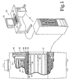
- the apparatus includes a plurality of primary magnet coils 10 which generate a temporally constant magnetic field along a longitudinal or z-axis of a central bore 12.
- the primary magnet coils are supported by a former 14 and received in a toroidal helium vessel or can 16.
- the can 16 is filled with liquid helium to maintain the primary magnet coils at superconducting temperatures.
- the can 16 is surrounded by one or more cold shields 18 which are supported in a vacuum dewar 20.
- a whole body gradient coil assembly 30 includes x, y, and z-coils mounted around the bore 12.
- the gradient coil assembly is a self-shielded gradient coil assembly that includes primary x, y, and z-coil assemblies 32 potted in a dielectric former 34 and a secondary or shield gradient coil assembly 36 that is supported on a bore defining cylinder 38 of the vacuum dewar 20.
- the dielectric former 34 with potted gradient coils can function as a bore liner or a cosmetic bore liner can be inserted to line it.
- shims (not shown) for adjusting the magnetic field are positioned as needed between the primary and shield coil dielectric formers.
- a whole body RF coil 40 is mounted inside the gradient coil assembly 30.
- a whole body RF shield 42 e.g. a layer of copper mesh, is mounted between RF coil 40 and the gradient coil assembly 30.
- An operator interface and control station 50 includes a human-readable display such as a video monitor 52 and an operator input means including a keyboard 54 and a mouse 56. Track balls, light pens, and other operator input devices are also contemplated.
- Computer racks 58 hold a magnetic resonance sequence memory and controller, a reconstruction processor, and other computer hardware and software for controlling the radio frequency coil 40 and the gradient coil 30 to implement any of a multiplicity of conventional magnetic resonance imaging sequences, including echo-planar, echo-volume, spin echo, and other imaging sequences. Echo-planar and echo-volume imaging sequences are characterized by short data acquisition times and high gradient strengths and slew rates.
- the racks 58 also hold a digital transmitter for providing RF excitation and resonance manipulation signals to the RF coil and a digital receiver for receiving and demodulating magnetic resonance signals.
- An array processor and associated software reconstruct the received magnetic resonance signals into an image representation which is stored in computer memory, on disk, or in other recording media.
- a video processor selectively extracts portions of the stored reconstructed image representation and formats the-data for display by the video monitor 52.
- An image printer can also be provided for making paper copies of selected images.
- the diameter and length of the bore 12 have a size ratio of about 1:1.
- the present invention is also applicable to other magnets, particularly magnets with limited main magnetic field uniformity. Typically, one might expect magnets with a bore length to diameter ratio of up to 1.5:1 to be candidates for the present invention.
- the present invention will also be applicable to magnetic resonance imagers with longer bores in which there is a sufficient main magnetic field non-uniformity, particularly radial field components, in the area of the gradient coils to cause image degradation due to vibration or in which there are sufficient net forces that mechanical mounting of the gradient coils becomes difficult.
- the main magnetic field magnets 10 produce a main magnetic field B 0 over the imaging volume.
- the z-component of the main magnetic field B z0 remains constant over a central imaging region of about 40 to 45 centimetres in diameter in a x,y plane at the magnetic isocenter.
- the imaging region is shorter than 40 centimetres.
- the B field changes significantly at larger axial or z-displacements from isocenter and with radial or ⁇ displacement from the central axis of the bore.
- the dependence of B z0 on the axial and radial positions becomes more significant around the gradient and RF coil locations, typically the region bounded by 30 cm.
- the second problem deals with the interaction between the current density for a transverse x or y-gradient coil and both the B ⁇ 0 and B z0 components of the main magnetic field.
- the result of such an interaction is again determined from the Lorentz force equation, but is a radially directed net force. Due to the azimuthal dependence of the transverse gradient's current density, the radially directed force is along the x or y-direction for an x or y-gradient coil, respectively. Again, the magnitude of this force is dependent on the value of the static magnetic fields B ⁇ 0 and B z0 components at the locations of the current lines for the x and y-gradient coils. Because the radius of the x and y-gradient coils is different, the value of the corresponding force will also be different. The value of the components of B 0 change with radial position.
- the z-gradient coil is self-shielded, having an inner or primary winding 60 of radius a and an outer or secondary shield coil 62 of radius b.
- the primary z-gradient coil is preferably circular loops wound on the dielectric former 34 and potted in epoxy or other resin.
- the shield z-gradient coil is preferably circularly wound on the dielectric former 38 that is incorporated into the vacuum dewar.
- the current density for the inner gradient coil J ⁇ a (z) is azimuthally directed and varies only along the axial direction of the coil.
- the current density for the outer gradient coil J ⁇ b (z) is azimuthally directed and also varies along the axial direction of the coil.
- the Fourier transform pairs for j ⁇ a,b and B ⁇ 0 a,b are: These equations can be used to obtain the Fourier or k-space representation of the net thrust force as: Because B ⁇ 0 a,b (z) is a pure real, odd-symmetric function of z:
- the expression of the axial z-component of the magnetic field due to the gradient coil B z , in the three regions which the two coils define can be simplified, due to the behavior of the current density. More specifically, no angular dependence is considered for a current which is uniform around the circumference of a cylindrical gradient coil. The current in the z-gradient coil is restricted to vary along the z-direction. With these constraints, the expression of B z in the three regions is: where j ⁇ a (k), j ⁇ b (k) are the Fourier transforms of the current densities of the inner coil of radius a and the outer coil of radius b, respectively.
- the z-gradient coil generated magnetic field B z is linear in the internal region of both coils and zero outside the two coils.
- B z in the region b ⁇ is set to zero, i.e., Equation (6c) is set to zero.
- the current is preferably restricted to become zero at the ends of the coil which restricts the values that k n can take.
- Equation (20) Equation (20)
- the functional E can be defined as: where B zSC and F zSC net are the prespecified constraint values of the magnetic field at the constraint points and the z-directed thrust force, respectively.
- the D jn matrix can correspond to either the magnetic field expression or to the z-directed thrust force expression.
- Equation (24a) For the expression of B ⁇ 0 a,b (z), data is obtained from the actual main magnet 10. Due to the antisymmetry of the B ⁇ 0 a,b (z), only positive z-values are generated.
- Q corresponds to the total number of points along z
- B ⁇ a,b is the corresponding value of B ⁇ 0 a,b (z) at the location z ⁇ .
- the Fourier transform B ⁇ 0 a,b (k) is:
- the Lagrangian multipliers are determined.
- the Fourier components of the current density for the primary or inner gradient coil in matrix form are:
- the next step is the process for discretization of the continuous current distribution for both coils.
- the continuous current distribution is divided into positive and negative current regions. Integrating the area underneath each region, the total current contained in each region is obtained.
- discrete current loops are positioned on a dielectric former to mimic the behavior of the continuous current pattern.
- Each region is filled with discrete wires carrying the prescribed amount of current. The amount of current is the same for each wire loop, in the preferred embodiment.
- the continuous current density is divided into smaller segments which correspond to the selected equal amount of current. The selected current amount may be iteratively adjusted in order to match the continuous current densities in the selected current regions more closely.
- Each wire is placed at the midpoint of the corresponding segment in order to obtain an equal distribution from both sides of the segment.
- This current distribution is then analyzed to calculate the generated magnetic field to assure that the desired magnetic field is, in fact, obtained.
- the inner or primary coil has a radius of about 340 millimetres and a length of about 700 to 900 millimetres.
- the outside or shield coil is about 385 millimetres in radius.
- Five constraint points are preferably chosen to define the characteristics of the field and the thrust force.
- the field is to be constrained inside a 40 cm. to 50 cm. generally ellipsoidal imaging volume.
- the first constraint point establishes a gradient field strength, e.g., about 13.5 mT/m.
- the second constraint point defines the linearity of the field along the gradient axis.
- the magnetic field is confined to vary not more than 5%.
- the remaining two constraints define the uniformity of the field across a plane perpendicular to the gradient axis.
- the magnetic field is constrained to stay within 7% of its actual value at a radial distance of about 22 cm. from the center of the coils.
- the last constraint point defines the value of the z-directed thrust force which is preferably less than -1.0e -08 Newtons.
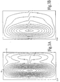
- a suitable primary gradient coil meeting these constraints is illustrated in FIGURE 2A and a suitable outer or shield gradient coil meeting these conditions is illustrated in FIGURE 2B. It will be noted that the primary gradient coil has several force correcting windings 64 of reversed polarity at its ends or extremes. If these reverse polarity windings were removed, the gradient coil would suffer a net longitudinal force component in excess of the above-discussed constraints.
- the force correcting current for cancelling the axial force can be determined iteratively. More specifically, several coil windings are disposed at the ends of one of the primary and secondary coils, preferably the primary coils. The net force on the gradient coil assembly during a gradient current pulse is measured. The current flow through the force correcting windings (or the number of force correcting loops) is iteratively adjusted until the axial force is substantially zeroed.
- the gradient coil assembly further includes an x-gradient coil and a y-gradient coil.
- the x and y-gradient coils are of substantially the same construction, but rotated 90°. Of course, because one is laminated over the other, they will have a small difference in radius.
- the x and y-gradient coils each include four substantially identical windings arranged symmetrically on either side of the isocenter.
- Each of the quadrants of the primary x or y-gradient coil contains a winding substantially as illustrated in FIGURE 3A.
- Each of the quadrants of the shield x or y-gradient coil contains a winding substantially as illustrated in FIGURE 3B.
- a current distribution is again calculated to produce the selected gradient strength, minimize stored energy, and zero the net lateral Lorentz forces.
- the total current density can be represented as: where ⁇ ( ⁇ - ⁇ 0 ) is the restriction that the current is confined on a cylindrical surface of radius ⁇ 0 .
- the x and y-gradient coils are self-shielded. That is, they have an inner or primary coil of radius a and an outer secondary or shield coil of radius b.
- the current density for the outer coil of radius b is analogous to Equation (30).
- the interaction between the components of the current density and the corresponding components of the main magnetic field yields an x-directed Lorentz force for self-shielded x-gradient coils and a y-direction force for self-shielded y-gradient coils.
- the following discussion focuses on x-gradient coils. However, it is to be appreciated that the same discussion is equally applicable to y-gradient coils which will be of the same construction but rotated 90° and of slightly different radius.
- the expression for F x net from Equation (32b) is rewritten as: where * represents the complex conjugate of the Fourier transforms of the two components of the main magnetic field.
- Equation (46) is the same as Equation (28), the expressions of the continuous current distribution for both coils is found by following the steps described above.
- ⁇ ⁇ J 0
- the contour plots of the current density are determined by: where N is the number of the current contours, S min is the minimum value of the current density
- S inc S max -S min N with S max representing the maximum value of the current density.
- S max representing the maximum value of the current density.
- the contours which are generated by this method follow the flow of the current and the distance between them corresponds to a current equal to an amount of S inc in amps.
- the discrete wires are positioned to coincide with these contour lines.
- the self-shielded force free x-gradient coil has a radius of the inner coil of about 1/3 metre and a length which is about -100 to 900 mm.
- the radius of the outer coil is about 0.4 metres.
- the number of Fourier coefficients which are used is equal to the total number of constraint points increased by 1.
- four constraint points are chosen to specify the quality of the magnetic field inside a 40-50 cm. by 25 cm. ellipsoidal volume, and to eliminate the net Lorentz force for the whole gradient coil system.
- the first constraint sets the strength of the gradient field, e.g. 13.5 mT/m.
- the second constraint specifies the linearity of the gradient field along the x-axis and up to the distance of 25 cm. from the isocenter of the gradient field, e.g., 5%.
- the third constraint specifies the uniformity of the gradient field along the z-axis at a distance up to ⁇ 6 cm. from the isocenter of the gradient field, e.g., 12%.
- the fourth constraint specifies the value of the net x-directed force on the gradient sets location, e.g., 1x10 -7 Newtons.
- the current in the force correcting winding effectively flows in an opposite spiral direction to the primary coil portion 70.
- the current distribution and number of turns in the force cancelling coil portion 72 is selected to zero the net x or y-direction force generated by the primary coil section 70 of FIGURE 3A.
- similar force free results can also be obtained by placing a winding having an opposite sense than the secondary x or y-gradient coil near an outer edge of that coil. The amperage through the force offsetting windings or the number of windings are adjusted until a current density is achieved which produces an x or y-force component which is equal and opposite to the force component generated by the other x or y-gradient coils.
- force balancing coils are applied to only the primary winding of shielded gradient coils in the preferred embodiment, it is to be appreciated that the primary and secondary coils can each be individually force balanced.
Landscapes
- Physics & Mathematics (AREA)
- Condensed Matter Physics & Semiconductors (AREA)
- General Physics & Mathematics (AREA)
- Magnetic Resonance Imaging Apparatus (AREA)
Claims (6)
- Gerät zur Bilderzeugung mit magnetischer Resonanz, das Folgendes umfasst: einen Hauptmagneten (10) zur Erzeugung eines temporär konstanten Magnetfelds durch eine Patientenaufnahmeöffnung (12); eine Gradientenfeldspulenanordnung (30) mit einer Primärspule (32) und einer Abschirmungsspule (36) zur Erzeugung von Magnetfeldern, die in der genannten Öffnung Magnetfeldgradienten bilden und dazu neigen, außerhalb der Patientenaufnahmeöffnung aufgehoben zu werden; und eine HF-Spule (4) zur Erzeugung von Magnetresonanz in der Öffnung; wobei das genannte temporär konstante Magnetfeld Komponenten an der Gradientenfeldspulenanordnung hat, die sich in Bezug auf die Öffnung in axialer und radialer Richtung erstrecken und die während des Betriebs mit dem Strom, der an die Primär- und Abschirmungsspulen (32, 36) der Gradientenfeldspulenanordnung angelegt wird, auf eine solche Weise in Wechselwirkung treten, dass die Primärund Abschirmungsspulen (32, 36) eine Lorentz-Nettokraft erfahren, wobei die Primärspule (32) oder die Abschirmungsspule (36) zusätzliche Kraftkorrekturwicklungen (64, 72) haben, die jeweils angrenzend an Kantenbereiche der Primärspule oder der Abschirmungsspule (32, 36), axial vom Isozentrum des Magnetfelds abgesetzt, angeordnet sind, dadurch gekennzeichnet, dass den Kraftkorrekturwicklungen während des Betriebs Strom zugeführt wird, und zwar in einer Richtung, die der Richtung des der betreffenden Primär- oder Abschirmungsspule (32, 36) zugeführten Stroms entgegengesetzt ist, so dass die Kraftkorrekturwicklungen eine Lorentz-Kraft erfahren, wobei der genannte Strom, der den Kraftkorrekturwicklungen zugeführt wird, so beschaffen ist, dass die genannte durch die Kraftkorrekturwicklungen erfahrene Lorentz-Kraft gleich und entgegengesetzt zu der von den Primär- oder Abschirmungsspulen (32, 36) erfahrenen Lorentz-Nettokraft ist.
- Gerät zur Bilderzeugung mit magnetischer Resonanz nach Anspruch 1, dadurch gekennzeichnet, dass die Patientenaufnahmeöffnung (12) eine Länge/Durchmesser-Verhältnis von weniger als 1,5:1 hat.
- Gerät zur Bilderzeugung mit magnetischer Resonanz nach Anspruch 1 dadurch gekennzeichnet, dass die Patientenaufnahmeöffnung (12) eine Länge/Durchmesser-Verhältnis von 1:1 hat.
- Gerät zur Bilderzeugung mit magnetischer Resonanz nach Anspruch 1, 2 oder 3, dadurch gekennzeichnet, dass die Primär- und Abschirmungsspulen (32, 36) jeweils vier symmetrisch angeordnete Thumbprint-Spulen (70) haben, um transversal zur Längsachse der Öffnung (12) einen Magnetfeldgradienten zu erzeugen, wobei die durch die Thumbprint-Spulen (70) fließenden Stromimpulse in Wechselwirkung mit den axialen und radialen Magnetfeldkomponenten treten, um eine radiale Lorentz-Kraft zu erzeugen, wobei die Kraftkorrekturwicklungen kraftausgleichende Stromschleifen (72) enthalten, die angrenzend an einen Kantenbereich von mindestens einer der Primär- und Abschirmungsspulen (32, 36) und axial abgesetzt vom Isozentrum angeordnet sind, um Stromflüsse zu führen, die in entgegengesetzter Richtung zu einer am dichtesten angrenzenden Thumbprint-Spule (70) zirkulieren, um die genannte radiale Lorentz-Kraft entlang der radialen Richtung auszugleichen.
- Gerät zur Bilderzeugung mit magnetischer Resonanz nach Anspruch 1, 2 oder 3, dadurch gekennzeichnet, dass die Gradientenfeldspulenanordnung (30) eine primäre z-Gradientenspule (32) mit einer Reihe von Schleifenspulen (60) umfasst, die um einen zylindrischen Spulenkörper (34) herum angeordnet sind, um entlang der Längsachse der Öffnung (12) ein z-Gradientenfeld zu erzeugen, und dass die Kraftkorrekturwicklungen Schleifen (64) haben, die um Enden des zylindrischen Spulenkörpers (34) herum verlaufen und mit den z-Gradienten-Schleifenspulen (60) in Reihe geschaltet sind.
- Gerät zur Bilderzeugung mit magnetischer Resonanz nach Anspruch 1, 2 oder 3, dadurch gekennzeichnet, dass die Gradientenfeldspulenanordnung (30) eine primäre z-Gradientenspule hat, um entlang der Längsachse der Öffnung (12) ein z-Gradientenfeld zu erzeugen, weiterhin umfassend: einen zylindrischen Spulenkörper (34); eine erste Vielzahl von Schleifen (60), die auf einer erste Seite des Isozentrums um den Spulenkörper (34) herum verlaufen und Stromimpulse in einer ersten Richtung um den Spulenkörper herum führen; eine zweite Vielzahl von Schleifen (60), die auf einer zweiten zweite Seite des Isozentrums um den Spulenkörper (34) herum verlaufen und um das Isozentrum herum symmetrisch mit der ersten Vielzahl von Schleifen (60) sind, wobei die zweite Vielzahl von Schleifen (60) Stromimpulse in einer zweiten Richtung um den Spulenkörper (34) herum und entgegengesetzt zur ersten Richtung führt, wobei die Stromimpulse durch die erste und die zweite Vielzahl von Schleifen (60) fließen und mit den genannten radialen Magnetfeldkomponenten in Wechselwirkung treten, um eine axiale Lorentz-Kraft zu verursachen; erste kraftausgleichende Spulen (64), die um den Spulenkörper (34) herum auf der ersten Seite des Isozentrums und axial davon abgesetzt verlaufen und Stromimpulse in der genannten zweiten Richtung führen; und zweite kraftausgleichende Spulen (64), die um den Spulenkörer (34) herum auf der zweiten Seite des Isozentrums und axial davon abgesetzt verlaufen und Stromimpulse in der genannten ersten Richtung führen, wobei die Stromimpulse, die durch die ersten und zweiten kraftausgleichenden Spulen (64) fließen, mit den genannten radialen Magnetfeldkomponenten in Wechselwirkung treten, um eine axiale Kraft zu verursachen, die die genannte axiale Lorentz-Kraft ausgleicht.
Applications Claiming Priority (2)
| Application Number | Priority Date | Filing Date | Title |
|---|---|---|---|
| US303620 | 1989-01-30 | ||
| US08/303,620 US5545996A (en) | 1994-03-15 | 1994-09-09 | Gradient coil with cancelled net thrust force |
Publications (2)
| Publication Number | Publication Date |
|---|---|
| EP0701143A1 EP0701143A1 (de) | 1996-03-13 |
| EP0701143B1 true EP0701143B1 (de) | 2003-11-12 |
Family
ID=23172935
Family Applications (1)
| Application Number | Title | Priority Date | Filing Date |
|---|---|---|---|
| EP95305393A Expired - Lifetime EP0701143B1 (de) | 1994-09-09 | 1995-08-01 | Gerät zur Bilderzeugung mit magnetischer Resonanz |
Country Status (4)
| Country | Link |
|---|---|
| US (1) | US5545996A (de) |
| EP (1) | EP0701143B1 (de) |
| JP (1) | JP3682627B2 (de) |
| DE (1) | DE69532101T2 (de) |
Families Citing this family (19)
| Publication number | Priority date | Publication date | Assignee | Title |
|---|---|---|---|---|
| JPH08252235A (ja) * | 1995-03-16 | 1996-10-01 | Toshiba Corp | 磁気共鳴映像装置 |
| DE19511834A1 (de) * | 1995-03-30 | 1996-10-02 | Siemens Ag | Diagnostisches Magnetresonanzgerät |
| US5942898A (en) * | 1996-12-13 | 1999-08-24 | Picker International, Inc. | Thrust balanced bi-planar gradient set for MRI scanners |
| FI103384B (fi) * | 1997-11-28 | 1999-06-30 | Nexstim Oy | Stimulointikärki ja menetelmä stimulaattorikelan äänen vaimentamiseksi |
| US6765381B2 (en) * | 2001-08-10 | 2004-07-20 | Varian, Inc. | Extended maxwell pair gradient coils |
| GB0204023D0 (en) * | 2002-02-20 | 2002-04-03 | Tesla Engineering Ltd | Gradient coil structure for magnetic resonance imaging |
| WO2004070412A1 (en) * | 2003-02-05 | 2004-08-19 | Koninklijke Philips Electronics N.V. | Compensation of magnetic field disturbances due to vibrations in an mri system |
| DE10310356A1 (de) * | 2003-03-10 | 2004-10-07 | Siemens Ag | Magnetresonanzgerät mit einem Grundfeldmagneten und wenigstens einer Gradientenspulen |
| US7230426B2 (en) * | 2003-06-20 | 2007-06-12 | General Electric Company | Split-shield gradient coil with improved fringe-field |
| RU2008129669A (ru) * | 2005-12-20 | 2010-01-27 | Конинклейке Филипс Электроникс Н.В. (Nl) | Магнитно-резонансный сканер с градиентной катушкой, расположенной рядом с обмотками основного магнита |
| EP2041594A2 (de) | 2006-07-07 | 2009-04-01 | Koninklijke Philips Electronics N.V. | Mri-gradientenspulen-baugruppe mit geräuschunterdrückung |
| JP4852053B2 (ja) * | 2008-01-23 | 2012-01-11 | 株式会社日立メディコ | 磁気共鳴イメージング装置 |
| CZ2010384A3 (cs) * | 2010-05-18 | 2011-07-13 | Ceské vysoké ucení technické v Praze - fakulta | Zapojení feromagnetické sondy pro merení gradientu magnetického pole |
| US9182465B2 (en) * | 2011-03-04 | 2015-11-10 | Siemens Aktiengesellschaft | MRT gradient system with integrated main magnetic field generation |
| US8766635B2 (en) * | 2011-06-30 | 2014-07-01 | General Electric Company | System and apparatus for balancing radial forces in a gradient coil |
| EP3230757B1 (de) * | 2014-12-09 | 2025-08-06 | Synaptive Medical Inc. | System und verfahren zur konstruktion einer elektromagnetischen spule |
| EP3561534A1 (de) * | 2018-04-24 | 2019-10-30 | Siemens Healthcare GmbH | Gradientenspuleneinheit für ein magnetresonanzgerät |
| JP7076339B2 (ja) * | 2018-09-04 | 2022-05-27 | 富士フイルムヘルスケア株式会社 | 磁気共鳴イメージング装置 |
| CN112748380B (zh) * | 2019-10-29 | 2024-03-19 | 西门子(深圳)磁共振有限公司 | 用于磁共振成像装置的梯度线圈及磁共振成像装置 |
Family Cites Families (13)
| Publication number | Priority date | Publication date | Assignee | Title |
|---|---|---|---|---|
| US4617516A (en) * | 1983-09-06 | 1986-10-14 | General Electric Company | Axial magnetic field gradient coil suitable for use with NMR apparatus |
| US4646024A (en) * | 1983-11-02 | 1987-02-24 | General Electric Company | Transverse gradient field coils for nuclear magnetic resonance imaging |
| US4737716A (en) * | 1986-02-06 | 1988-04-12 | General Electric Company | Self-shielded gradient coils for nuclear magnetic resonance imaging |
| US5278504A (en) * | 1989-06-16 | 1994-01-11 | Picker International, Inc. | Gradient coil with off center sweet spot for magnetic resonance imaging |
| US5296810A (en) | 1992-03-27 | 1994-03-22 | Picker International, Inc. | MRI self-shielded gradient coils |
| DE4029477C2 (de) * | 1989-09-29 | 1994-06-01 | Siemens Ag | Tesserale Gradientenspule für Kernspin-Tomographiegeräte |
| US5177442A (en) * | 1991-07-01 | 1993-01-05 | General Electric Company | Transverse gradient coils for imaging the head |
| US5185576A (en) * | 1991-08-12 | 1993-02-09 | General Electric Company | Local gradient coil |
| US5266913A (en) * | 1991-08-27 | 1993-11-30 | British Technology Group Usa Inc. | Screened electromagnetic coil of restricted length having optimized field and method |
| DE4142263C2 (de) * | 1991-12-20 | 1994-03-24 | Bruker Analytische Messtechnik | Gradientenspulensystem |
| US5349297A (en) * | 1992-03-27 | 1994-09-20 | Picker International Inc. | Combined self shielded gradient coil and shimset |
| US5372137A (en) * | 1993-01-19 | 1994-12-13 | The Mcw Research Foundation, Inc. | NMR local coil for brain imaging |
| GB9311321D0 (en) * | 1993-06-02 | 1993-07-21 | British Tech Group | Apparatus for and methods of acoustic and magnetic screening |
-
1994
- 1994-09-09 US US08/303,620 patent/US5545996A/en not_active Expired - Lifetime
-
1995
- 1995-08-01 DE DE69532101T patent/DE69532101T2/de not_active Expired - Lifetime
- 1995-08-01 EP EP95305393A patent/EP0701143B1/de not_active Expired - Lifetime
- 1995-09-04 JP JP25016495A patent/JP3682627B2/ja not_active Expired - Fee Related
Also Published As
| Publication number | Publication date |
|---|---|
| EP0701143A1 (de) | 1996-03-13 |
| US5545996A (en) | 1996-08-13 |
| JP3682627B2 (ja) | 2005-08-10 |
| DE69532101T2 (de) | 2004-06-09 |
| JPH0884720A (ja) | 1996-04-02 |
| DE69532101D1 (de) | 2003-12-18 |
Similar Documents
| Publication | Publication Date | Title |
|---|---|---|
| EP0701143B1 (de) | Gerät zur Bilderzeugung mit magnetischer Resonanz | |
| EP0231879B1 (de) | Selbstgeschmirmte Gradientspulen für Abbildung in kernmagnetischer Resonanz | |
| US5614827A (en) | Method and apparatus for shimming a magnet system of a nuclear magnetic resonance tomography system | |
| US6342787B1 (en) | Real-time multi-axis gradient distortion correction using an interactive shim set | |
| EP0136536A2 (de) | Axiale Magnetfeld-Gradientenspule zur Anwendung in einem magnetischen Kernresonanzapparat | |
| US9658303B2 (en) | Gradient coil with correction windings and method for production thereof | |
| RU2614648C2 (ru) | Использование градиентных катушек для коррекции неоднородностей поля b0 высших порядков при формировании изображения методом магнитного резонанса | |
| US6078177A (en) | Flared gradient coil set with a finite shield current | |
| US5942898A (en) | Thrust balanced bi-planar gradient set for MRI scanners | |
| EP1004890A2 (de) | Abgeschirmte Gradientenspulenanordnung für die Magnetresonanzbildgebung | |
| US20080164878A1 (en) | Minimum Energy Shim Coils For Magnetic Resonance | |
| EP0695950B1 (de) | Anordnungen von Gradientenspulen für Gerät zur Bilderzeugung durch magnetische Resonanz | |
| US5655533A (en) | Actively shielded orthogonal gradient coils for wrist imaging | |
| CN110412492A (zh) | 用于磁共振设备的梯度线圈单元 | |
| EP0690312B1 (de) | Asymmetrische Gradientenspulen zur Bilderzeugung mittels magnetischer Resonanz | |
| US6100692A (en) | Gradient coil set with a finite shield current | |
| EP0913699B1 (de) | Ebenes Gradientenspulensystem für die Magnetresonanzbildgebung, welches auf nur einer Seite des Untersuchungsobjekts angeordnet ist | |
| EP0154996B1 (de) | Vorrichtung mit Trimmspulen-Korrektur zur Bilderzeugung mittels magnetischer Resonanz | |
| US6236203B1 (en) | Super shielding of finite length structures in open magnetic and electric systems | |
| EP3828580B1 (de) | Verfahren und system zur kompensation von streumagnetfeldern in einem magnetresonanzbildgebungssystem mit mehreren untersuchungsbereichen | |
| US6278275B1 (en) | Gradient coil set with non-zero first gradient field vector derivative | |
| US4644277A (en) | NMR tomography apparatus | |
| Shvartsman et al. | Application of the SUSHI method to the design of gradient coils | |
| US6717409B2 (en) | Method for calculating conductor paths in a switched gradient coil system, and magnetic resonance tomography apparatus employing such a switched gradient coil system | |
| US6850066B2 (en) | Systems and methods for gradient compensation in magnetic resonance imaging |
Legal Events
| Date | Code | Title | Description |
|---|---|---|---|
| PUAI | Public reference made under article 153(3) epc to a published international application that has entered the european phase |
Free format text: ORIGINAL CODE: 0009012 |
|
| AK | Designated contracting states |
Kind code of ref document: A1 Designated state(s): DE FR GB NL |
|
| 17P | Request for examination filed |
Effective date: 19960904 |
|
| 17Q | First examination report despatched |
Effective date: 19980127 |
|
| RAP1 | Party data changed (applicant data changed or rights of an application transferred) |
Owner name: MARCONI MEDICAL SYSTEMS, INC. |
|
| GRAH | Despatch of communication of intention to grant a patent |
Free format text: ORIGINAL CODE: EPIDOS IGRA |
|
| RAP1 | Party data changed (applicant data changed or rights of an application transferred) |
Owner name: PHILIPS MEDICAL SYSTEMS (CLEVELAND), INC. |
|
| GRAS | Grant fee paid |
Free format text: ORIGINAL CODE: EPIDOSNIGR3 |
|
| GRAA | (expected) grant |
Free format text: ORIGINAL CODE: 0009210 |
|
| AK | Designated contracting states |
Kind code of ref document: B1 Designated state(s): DE FR GB NL |
|
| PG25 | Lapsed in a contracting state [announced via postgrant information from national office to epo] |
Ref country code: NL Free format text: LAPSE BECAUSE OF FAILURE TO SUBMIT A TRANSLATION OF THE DESCRIPTION OR TO PAY THE FEE WITHIN THE PRESCRIBED TIME-LIMIT Effective date: 20031112 Ref country code: FR Free format text: LAPSE BECAUSE OF FAILURE TO SUBMIT A TRANSLATION OF THE DESCRIPTION OR TO PAY THE FEE WITHIN THE PRESCRIBED TIME-LIMIT Effective date: 20031112 |
|
| REG | Reference to a national code |
Ref country code: GB Ref legal event code: FG4D |
|
| RAP2 | Party data changed (patent owner data changed or rights of a patent transferred) |
Owner name: KONINKLIJKE PHILIPS ELECTRONICS N.V. |
|
| REF | Corresponds to: |
Ref document number: 69532101 Country of ref document: DE Date of ref document: 20031218 Kind code of ref document: P |
|
| NLT2 | Nl: modifications (of names), taken from the european patent patent bulletin |
Owner name: KONINKLIJKE PHILIPS ELECTRONICS N.V. |
|
| NLV1 | Nl: lapsed or annulled due to failure to fulfill the requirements of art. 29p and 29m of the patents act | ||
| PLBE | No opposition filed within time limit |
Free format text: ORIGINAL CODE: 0009261 |
|
| STAA | Information on the status of an ep patent application or granted ep patent |
Free format text: STATUS: NO OPPOSITION FILED WITHIN TIME LIMIT |
|
| REG | Reference to a national code |
Ref country code: GB Ref legal event code: 746 Effective date: 20040903 |
|
| 26N | No opposition filed |
Effective date: 20040813 |
|
| EN | Fr: translation not filed | ||
| PGFP | Annual fee paid to national office [announced via postgrant information from national office to epo] |
Ref country code: GB Payment date: 20090901 Year of fee payment: 15 |
|
| PGFP | Annual fee paid to national office [announced via postgrant information from national office to epo] |
Ref country code: DE Payment date: 20101029 Year of fee payment: 16 |
|
| GBPC | Gb: european patent ceased through non-payment of renewal fee |
Effective date: 20100801 |
|
| PG25 | Lapsed in a contracting state [announced via postgrant information from national office to epo] |
Ref country code: GB Free format text: LAPSE BECAUSE OF NON-PAYMENT OF DUE FEES Effective date: 20100801 |
|
| PG25 | Lapsed in a contracting state [announced via postgrant information from national office to epo] |
Ref country code: DE Free format text: LAPSE BECAUSE OF NON-PAYMENT OF DUE FEES Effective date: 20130301 |
|
| REG | Reference to a national code |
Ref country code: DE Ref legal event code: R119 Ref document number: 69532101 Country of ref document: DE Effective date: 20130301 |