EP0701146A2 - Gammastrahlen-Szintillationsdetektor und eine Methode, das durch Stösse hervorgerufene Rauschen zu reduzieren - Google Patents
Gammastrahlen-Szintillationsdetektor und eine Methode, das durch Stösse hervorgerufene Rauschen zu reduzieren Download PDFInfo
- Publication number
- EP0701146A2 EP0701146A2 EP95306163A EP95306163A EP0701146A2 EP 0701146 A2 EP0701146 A2 EP 0701146A2 EP 95306163 A EP95306163 A EP 95306163A EP 95306163 A EP95306163 A EP 95306163A EP 0701146 A2 EP0701146 A2 EP 0701146A2
- Authority
- EP
- European Patent Office
- Prior art keywords
- pulse
- pulses
- detector
- gamma ray
- time interval
- Prior art date
- Legal status (The legal status is an assumption and is not a legal conclusion. Google has not performed a legal analysis and makes no representation as to the accuracy of the status listed.)
- Granted
Links
Images

Classifications
-
- G—PHYSICS
- G01—MEASURING; TESTING
- G01V—GEOPHYSICS; GRAVITATIONAL MEASUREMENTS; DETECTING MASSES OR OBJECTS; TAGS
- G01V5/00—Prospecting or detecting by the use of ionising radiation, e.g. of natural or induced radioactivity
- G01V5/04—Prospecting or detecting by the use of ionising radiation, e.g. of natural or induced radioactivity specially adapted for well-logging
- G01V5/06—Prospecting or detecting by the use of ionising radiation, e.g. of natural or induced radioactivity specially adapted for well-logging for detecting naturally radioactive minerals
Definitions
- This invention relates generally to apparatus for logging while drilling and more particularly to logging while drilling tools which include gamma ray scintillation detectors for measuring the natural radioactivity of geological formations surrounding a borehole.
- Gamma ray sensing instruments including a sodium iodide (Nal) crystal in combination with a photo multiplier tube (PMT) have been used for many years to sense and count the number of gamma rays striking a measurement tool in a borehole. Such instruments have been used with great success in open hole logging tools to measure the extent of natural radioactivity of earth formations which surround the borehole. When such gamma ray sensing instruments are used in a logging while drilling (LWD) environment, however, tremendous shocks are imparted to the housing of the LWD tools. Such shocks can induce voltage pulses from the detector that have pulse amplitudes similar to the amplitudes generated by gamma rays striking the detector.
- LWD logging while drilling
- a primary object of this invention is to provide a method and apparatus for a gamma ray detector to distinguish gamma ray pulses from shock induced pulses.
- Another object of this invention is to provide a method and apparatus for a gamma ray detector, used in a tool to measure natural radioactivity of earth formations surrounding a borehole, by which shock induced pulses which are counted are minimized, so as to maximize the probability that if a detector pulse is counted, it is a gamma ray induced pulse and not a shock induced pulse.
- apparatus and a method are provided by which detector pulses are actually counted as true gamma ray counts only if a detector pulse has occurred after a predetermined time interval has elapsed after a previous pulse has occurred.
- the apparatus is provided such that if a detector pulse is produced within such predetermined time interval, such time interval begins again for determining whether or not a subsequent detector pulse is a gamma ray pulse to be counted or a shock induced pulse which is not to be counted.
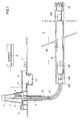
- FIG 1 illustrates a logging while drilling (LWD) tool 100 connected in tandem with a drilling assembly including drill bit 50.
- Such tool 100 includes a gamma ray detector assembly 108 for measurement of gamma rays produced by naturally radioactive elements of the surrounding formations 8.
- the detector assembly 108 is electrically connected to an electronics module 300 which may be a separate "sub” as illustrated or may be disposed in the body of LWD tool 100.
- a communication sub 400 is also provided as illustrated in the drilling assembly.
- the LWD tool 100 is shown for illustration purposes as being in an inclined portion of a borehole at the end of a drill string 6 which turns in a borehole 12 which is formed in formation 8 by penetration of bit 50.
- a drilling rig 5 turns drill string 6.
- Drilling rig 5 includes a motor 2 which turns a kelly 3 by means of a rotary table 4.
- the drill string 6 includes sections of drill pipe connected end-to-end to the kelly 3 and turned thereby.
- the MWD tool 200, electronics module 300 and the LWD tool 100 and communication sub 400 are all connected in tandem with drill string 6. Such subs and tools form a bottom hole drilling assembly between the drill string 6 of drill pipe and the drill bit 50.
- Drilling fluid or "mud” is forced by pump 11 from mud pit 13 via stand pipe 15 and revolving injector head 7 through the hollow center of kelly 3 and drill string 6, and the bottom hole drilling assembly to the bit 50.
- Such mud acts to lubricate drill bit 50 and to carry borehole cuttings or chips upwardly to the surface via annulus 10.
- the mud is returned to mud pit 13 where it is separated from borehole cuttings and the like, degassed, and returned for application again to the drill string 6.
- the communication sub 400 receives output signals from sensors of the LWD tool 100 and from computers in the downhole electronics module 300 and MWD tool 200. Such communications sub 400 is designed to transmit coded acoustic signals representative of such output signals to the surface through the mud path in the drill string 6 and downhole drilling assembly. Such acoustic signals are sensed by transducer 21 in standpipe 15, where such acoustic signals are detected in surface instrumentation 14.
- the communication sub 400 including the surface instrumentation necessary to communicate with it, are arranged as the downhole and surface apparatus disclosed in U.S. Patent 4,479,564 and U.S. Patent 4,637,479, which patents are incorporated herein by reference.
- the communication sub 400 may advantageously include the communication apparatus disclosed in U.S. Patent 5,237,540. Such patent is assigned to the assignee of this application and is incorporated herein by reference.
- the gamma ray scintillation detector 108 including a Nal crystal 109 and photo multiplier tube (PMT) 110 of Figure 2, when used in a logging while drilling environment, is subject to high mechanical shocks. Such shocks can induce voltage pulses from the detector that have amplitudes similar to pulses induced by gamma rays.
- PMT photo multiplier tube
- the number of counts recorded by a gamma ray detector varies from a few counts per second to a few hundred counts per second. It is not uncommon for logging while drilling tools to receive several mechanical shocks per second at levels exceeding several hundred g's while drilling in hard rock formations. Hence, if each mechanical shock applied to the detector only generates a few, e.g., 2 to 10 voltage pulses, a significant bias can be added to the gamma ray countrate. Such bias results in an incorrect gamma ray activity being assigned to the formation surrounding the borehole and, without correction, reduces the commercial value of the data.
- the controlling parameter is the average countrate. Assuming a countrate near the upper limit encountered in logging while drilling, say 200 counts per second, it has been discovered that less than 2% of the gamma ray pairs will be separated by less than 100 microseconds. This fact, coupled with the discovery that arrival times for shock induced pulses are highly correlated, makes it possible to discriminate between gamma ray induced pulses and shock induced pulses of detector 108.
- the basic method for discrimination is to reject pairs of pulses separated by less than a predetermined time period and accept pulses that are separated from all other pulses by more than such predetermined time period. It has been found that such predetermined time period for the logging while drilling operations illustrated in Figure 1 may be selected from a range of 80 to 120 microseconds. Such predetermined time period is preferably about 100 microseconds.
- Figure 2 illustrates schematically the detector assembly 108 including a sodium iodide (Nal) crystal 109 and photo multiplier tube (PMT) 110 which have long been used in the measurement of gamma ray counts in the logging art.
- the voltage pulses of photomultiplier tube 110 are applied to electronics module 300, specifically the gamma ray counting apparatus 120 of this invention.
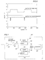
- Figure 3 illustrates a first embodiment of such apparatus 120 which receives voltage pulses on lead 121 from the PMT 110. After amplification by integrating amplifier 122 and pulse height discrimination by amplitude discriminator 124, such pulses are applied on lead 125 to a reset lead of one shot multivibrator 126. Such "One Shot" 126 produces an output pulse on lead 127 of a predetermined time length T each time a pulse is received at its reset terminal.
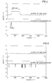
- Figure 4 shows on a lower voltage versus time (in microseconds) trace an input pulse of approximately 5 microseconds long applied on lead 125 to One Shot 126.
- the One Shot output on lead 127 is also illustrated in the upper trace.
- the One Shot output is a positive going pulse which is maintained for about 100 microseconds, after the input pulse has been removed.
- the positive pulse lasts 105 microseconds from the beginning of the input pulse.
- the example of Figure 4 is for the case where the detector 108 is not being subjected to shock forces. Accordingly, the five microsecond pulse on lead 125 (typical output pulse of discriminator 124) should be recognized as a gamma ray induced pulse because the output pulse on lead 127 is of a time interval equal to the time period of One-Shot 126.
- Figures 5 and 6 are examples of the output of One Shot 126 where the detector 108 is subjected to high shocks, e.g., 250-300g.
- the output pulse on lead 127 from the One Shot circuit has a time width longer than the 105 microsecond length for the single pulse case of Figure 4. In other words, if a new pulse is applied to One Shot 126 before 105 microseconds have elapsed from the previous input pulse, the One Shot is retriggered from the time of such new pulse.
- the added circuitry of Figure 3 shown connected by dashed leads 125', 127' and 129 may be provided for the One Shot circuit 126 so as not to apply its output directly to counter 128. Rather, a timer circuit 140 is provided with its input connected directly to the output of discriminator 124 via lead 125'. Timer 140 produces an output pulse on lead 141 after receipt of a pulse on lead 125' and after an elapsed time T' has occurred. The time T' is set to 110 microseconds, whereas the delay time T of One Shot 126 is set to 105 microseconds. As a result, if the pulse on lead 127' is not present and the pulse on lead 141 is present, the logic circuit 142 produces an output count on lead 129 for application to counter 128.
- the pulse on lead 127 has occurred and disappeared by the time the pulse on lead 141 has occurred, signifying that the pulse of One-Shot 126 was less than 110 microseconds, for example.
- the pulse on lead 129 reflects the occurrence of a gamma ray induced pulse, rather than multiple pulses of shock induced pulses.
- the pulse on lead 141 When the pulse on lead 141 occurs, it is fed back to the reset lead 143 of timer 140 so as to remove the pulse on lead 141 and re-configure the timer 140 for another pulse.
- a new pulse on leads 125 and 125' starts the process over such that pulses are created on lead 129 only if a pulse on lead 127 occurs and disappears within 105 microseconds without another pulse having occurred within that time.
- Figure 7 illustrates an alternative circuit to that shown in Figure 3 for insuring that only those pulses are counted from discriminator 124' which occur after a predetermined interval of time from the previous pulse.
- the timer 136 is reset and restarted with each pulse on lead 125.
- the timer 138 is started with a pulse on lead 125', but an output occurs on lead 160 only after the time set for it, e.g., 105 microseconds have elapsed. Immediately thereafter, it is reset by the voltage of its output being applied to its reset terminal via lead 161.
- the AND circuit 164 passes a pulse to counter 128' for counting. In other words, a pulse that triggers and resets timer 136 must simultaneously trigger timer 138 and another pulse must not re-trigger timer 136 before timer 138 has produced an output on lead 160.
Landscapes
- Life Sciences & Earth Sciences (AREA)
- Physics & Mathematics (AREA)
- Environmental & Geological Engineering (AREA)
- Geology (AREA)
- High Energy & Nuclear Physics (AREA)
- General Life Sciences & Earth Sciences (AREA)
- General Physics & Mathematics (AREA)
- Geophysics (AREA)
- Measurement Of Radiation (AREA)
- Geophysics And Detection Of Objects (AREA)
- Nuclear Medicine (AREA)
- Analysing Materials By The Use Of Radiation (AREA)
Applications Claiming Priority (2)
| Application Number | Priority Date | Filing Date | Title |
|---|---|---|---|
| US08/303,109 US5483061A (en) | 1994-09-07 | 1994-09-07 | Gamma ray scintillation detector apparatus and method for reducing shock induced noise |
| US303109 | 1994-09-07 |
Publications (3)
| Publication Number | Publication Date |
|---|---|
| EP0701146A2 true EP0701146A2 (de) | 1996-03-13 |
| EP0701146A3 EP0701146A3 (de) | 1997-02-26 |
| EP0701146B1 EP0701146B1 (de) | 2002-02-27 |
Family
ID=23170580
Family Applications (1)
| Application Number | Title | Priority Date | Filing Date |
|---|---|---|---|
| EP95306163A Expired - Lifetime EP0701146B1 (de) | 1994-09-07 | 1995-09-04 | Gammastrahlen-Szintillationsdetektor und eine Methode, das durch Stösse hervorgerufene Rauschen zu reduzieren |
Country Status (6)
| Country | Link |
|---|---|
| US (1) | US5483061A (de) |
| EP (1) | EP0701146B1 (de) |
| AU (1) | AU682276B2 (de) |
| CA (1) | CA2157538C (de) |
| DE (1) | DE69525580D1 (de) |
| NO (1) | NO311858B1 (de) |
Families Citing this family (13)
| Publication number | Priority date | Publication date | Assignee | Title |
|---|---|---|---|---|
| DE69725630D1 (de) * | 1996-01-25 | 2003-11-27 | Anadrill Int Sa | Verfahren und Vorrichtung zur Unterdrückung von mikrophonischem Geräusch in Proportional-Zählrohren beim Bohrlochmessen während des Bohrens |
| US5635711A (en) * | 1996-04-25 | 1997-06-03 | Schlumberger Technology Corporation | Apparatus and method for the suppression of microphonic noise in proportional counters for borehole logging-while-drilling |
| US5744803A (en) * | 1996-09-19 | 1998-04-28 | Saint-Gobain Industrial Ceramics, Inc. | Radiation detector assembly and method with discrimination between vibration and radiation induced events |
| FR2847678B1 (fr) * | 2002-11-27 | 2005-01-07 | Commissariat Energie Atomique | Detecteur de particules et procede de detection de particules associe |
| GB0228884D0 (en) * | 2002-12-11 | 2003-01-15 | Schlumberger Holdings | Method and system for estimating the position of a movable device in a borehole |
| US8492705B2 (en) * | 2009-10-23 | 2013-07-23 | Saint-Gobain Ceramics & Plastics, Inc. | Radiation detector and method of using a radiation detector |
| US8907289B2 (en) * | 2012-04-19 | 2014-12-09 | Schlumberger Technology Corporation | Subatomic particle detector capable of ignoring shock induced counts |
| US9018587B2 (en) | 2012-09-27 | 2015-04-28 | Saint-Gobain Ceramics & Plastics, Inc. | Radiation detection apparatus with noise compensation and a method of using the same |
| WO2014074898A1 (en) | 2012-11-09 | 2014-05-15 | Saint-Gobain Ceramics & Plastics, Inc. | Radiation detection apparatus using pulse discrimination and a method of using the same |
| US9040926B2 (en) | 2013-03-15 | 2015-05-26 | Cbg Corporation | Rugged scintillation crystal assembly |
| US8975574B2 (en) | 2013-05-23 | 2015-03-10 | Schlumberger Technology Corporation | Well-logging tool with azimuthal and spectral radiation detectors and related methods |
| US10242312B2 (en) | 2014-06-06 | 2019-03-26 | Quantico Energy Solutions, Llc. | Synthetic logging for reservoir stimulation |
| US11774628B2 (en) | 2019-05-24 | 2023-10-03 | Halliburton Energy Services, Inc. | Probabilistically distinguishing between true and false scintillator pulses |
Citations (3)
| Publication number | Priority date | Publication date | Assignee | Title |
|---|---|---|---|---|
| US4479564A (en) | 1979-04-12 | 1984-10-30 | Schlumberger Technology Corporation | System and method for monitoring drill string characteristics during drilling |
| US4637479A (en) | 1985-05-31 | 1987-01-20 | Schlumberger Technology Corporation | Methods and apparatus for controlled directional drilling of boreholes |
| US5237540A (en) | 1992-08-21 | 1993-08-17 | Schlumberger Technology Corporation | Logging while drilling tools utilizing magnetic positioner assisted phase shifts |
Family Cites Families (3)
| Publication number | Priority date | Publication date | Assignee | Title |
|---|---|---|---|---|
| US3013156A (en) * | 1958-01-22 | 1961-12-12 | Dresser Ind | Apparatus for supporting geiger counters |
| US4879463A (en) * | 1987-12-14 | 1989-11-07 | Schlumberger Technology Corporation | Method and apparatus for subsurface formation evaluation |
| US5023450A (en) * | 1990-04-12 | 1991-06-11 | Halliburton Logging Services, Inc. | Method for discriminating microphonic noise in proportional counters |
-
1994
- 1994-09-07 US US08/303,109 patent/US5483061A/en not_active Expired - Lifetime
-
1995
- 1995-08-29 AU AU30343/95A patent/AU682276B2/en not_active Ceased
- 1995-09-04 EP EP95306163A patent/EP0701146B1/de not_active Expired - Lifetime
- 1995-09-04 DE DE69525580T patent/DE69525580D1/de not_active Expired - Lifetime
- 1995-09-05 CA CA002157538A patent/CA2157538C/en not_active Expired - Fee Related
- 1995-09-06 NO NO19953510A patent/NO311858B1/no unknown
Patent Citations (3)
| Publication number | Priority date | Publication date | Assignee | Title |
|---|---|---|---|---|
| US4479564A (en) | 1979-04-12 | 1984-10-30 | Schlumberger Technology Corporation | System and method for monitoring drill string characteristics during drilling |
| US4637479A (en) | 1985-05-31 | 1987-01-20 | Schlumberger Technology Corporation | Methods and apparatus for controlled directional drilling of boreholes |
| US5237540A (en) | 1992-08-21 | 1993-08-17 | Schlumberger Technology Corporation | Logging while drilling tools utilizing magnetic positioner assisted phase shifts |
Also Published As
| Publication number | Publication date |
|---|---|
| EP0701146A3 (de) | 1997-02-26 |
| DE69525580D1 (de) | 2002-04-04 |
| CA2157538C (en) | 2004-02-17 |
| NO953510D0 (no) | 1995-09-06 |
| NO311858B1 (no) | 2002-02-04 |
| NO953510L (no) | 1996-03-08 |
| AU682276B2 (en) | 1997-09-25 |
| US5483061A (en) | 1996-01-09 |
| AU3034395A (en) | 1996-04-04 |
| CA2157538A1 (en) | 1996-03-08 |
| EP0701146B1 (de) | 2002-02-27 |
Similar Documents
| Publication | Publication Date | Title |
|---|---|---|
| US5483061A (en) | Gamma ray scintillation detector apparatus and method for reducing shock induced noise | |
| EP0323773B1 (de) | Vorrichtung zur Untersuchung des Erdbodens und der umgebenden Erdformation | |
| US5250806A (en) | Stand-off compensated formation measurements apparatus and method | |
| US6648083B2 (en) | Method and apparatus for measuring mud and formation properties downhole | |
| EP0321197B1 (de) | Verfahren zur Bohrlochmessung unter Verwendung von radioaktiven Tracerelementen | |
| CA2349763C (en) | Standoff compensation for nuclear measurements | |
| US7292942B2 (en) | Measuring formation density through casing | |
| US7408150B1 (en) | Well logging method for determining formation characteristics using pulsed neutron capture measurements | |
| US4415805A (en) | Method and apparatus for evaluating multiple stage fracturing or earth formations surrounding a borehole | |
| US7253402B2 (en) | Apparatus and method for determining thermal neutron capture cross section of a subsurface formation from a borehole using multiple detectors | |
| US5591967A (en) | Method and apparatus for determining neutron detector operability using gamma ray sources | |
| US5726951A (en) | Standoff compensation for acoustic logging while drilling systems | |
| EP0125024A1 (de) | Bohrlochwanddickenbestimmung mittels eines Verstärkung stabilisierten Detektors unter Ausnützung der natürlichen Gammastrahlung | |
| US4300043A (en) | Stabilized radioactive logging method and apparatus | |
| AU631609B2 (en) | Method and tool for gravel pack evaluation | |
| US10921486B2 (en) | Integrated logging tool | |
| US4691772A (en) | Process for obtaining permeability logs using radioactive drilling mud additives | |
| US11774628B2 (en) | Probabilistically distinguishing between true and false scintillator pulses | |
| US6552334B2 (en) | Wellbore caliper measurement method using measurements from a gamma-gamma density | |
| US5635711A (en) | Apparatus and method for the suppression of microphonic noise in proportional counters for borehole logging-while-drilling | |
| US5706003A (en) | Apparatus and method for cancellation of offset in gamma spectrum data | |
| US3264475A (en) | Method for calibrating a radioactive logging system | |
| EP0786674B1 (de) | Verfahren und Vorrichtung zur Unterdrückung von mikrophonischem Geräusch in Proportional-Zählrohren beim Bohrlochmessen während des Bohrens | |
| US4978851A (en) | Method and apparatus for measuring subsurface characteristics using pulsed neutron/gamma ray logging | |
| US3394256A (en) | Method of calibrating the scintillation detector of a chlorine logging system |
Legal Events
| Date | Code | Title | Description |
|---|---|---|---|
| PUAI | Public reference made under article 153(3) epc to a published international application that has entered the european phase |
Free format text: ORIGINAL CODE: 0009012 |
|
| AK | Designated contracting states |
Kind code of ref document: A2 Designated state(s): DE FR GB IT NL |
|
| PUAL | Search report despatched |
Free format text: ORIGINAL CODE: 0009013 |
|
| AK | Designated contracting states |
Kind code of ref document: A3 Designated state(s): DE FR GB IT NL |
|
| 17P | Request for examination filed |
Effective date: 19970816 |
|
| 17Q | First examination report despatched |
Effective date: 20000628 |
|
| GRAG | Despatch of communication of intention to grant |
Free format text: ORIGINAL CODE: EPIDOS AGRA |
|
| GRAG | Despatch of communication of intention to grant |
Free format text: ORIGINAL CODE: EPIDOS AGRA |
|
| GRAH | Despatch of communication of intention to grant a patent |
Free format text: ORIGINAL CODE: EPIDOS IGRA |
|
| GRAH | Despatch of communication of intention to grant a patent |
Free format text: ORIGINAL CODE: EPIDOS IGRA |
|
| REG | Reference to a national code |
Ref country code: GB Ref legal event code: IF02 |
|
| GRAA | (expected) grant |
Free format text: ORIGINAL CODE: 0009210 |
|
| AK | Designated contracting states |
Kind code of ref document: B1 Designated state(s): DE FR GB IT NL |
|
| PG25 | Lapsed in a contracting state [announced via postgrant information from national office to epo] |
Ref country code: NL Free format text: LAPSE BECAUSE OF FAILURE TO SUBMIT A TRANSLATION OF THE DESCRIPTION OR TO PAY THE FEE WITHIN THE PRESCRIBED TIME-LIMIT Effective date: 20020227 Ref country code: IT Free format text: LAPSE BECAUSE OF FAILURE TO SUBMIT A TRANSLATION OF THE DESCRIPTION OR TO PAY THE FEE WITHIN THE PRESCRIBED TIME-LIMIT;WARNING: LAPSES OF ITALIAN PATENTS WITH EFFECTIVE DATE BEFORE 2007 MAY HAVE OCCURRED AT ANY TIME BEFORE 2007. THE CORRECT EFFECTIVE DATE MAY BE DIFFERENT FROM THE ONE RECORDED. Effective date: 20020227 |
|
| REF | Corresponds to: |
Ref document number: 69525580 Country of ref document: DE Date of ref document: 20020404 |
|
| PG25 | Lapsed in a contracting state [announced via postgrant information from national office to epo] |
Ref country code: DE Free format text: LAPSE BECAUSE OF FAILURE TO SUBMIT A TRANSLATION OF THE DESCRIPTION OR TO PAY THE FEE WITHIN THE PRESCRIBED TIME-LIMIT Effective date: 20020528 |
|
| NLV1 | Nl: lapsed or annulled due to failure to fulfill the requirements of art. 29p and 29m of the patents act | ||
| ET | Fr: translation filed | ||
| PLBE | No opposition filed within time limit |
Free format text: ORIGINAL CODE: 0009261 |
|
| STAA | Information on the status of an ep patent application or granted ep patent |
Free format text: STATUS: NO OPPOSITION FILED WITHIN TIME LIMIT |
|
| 26N | No opposition filed |
Effective date: 20021128 |
|
| PGFP | Annual fee paid to national office [announced via postgrant information from national office to epo] |
Ref country code: FR Payment date: 20040908 Year of fee payment: 10 |
|
| PG25 | Lapsed in a contracting state [announced via postgrant information from national office to epo] |
Ref country code: FR Free format text: LAPSE BECAUSE OF NON-PAYMENT OF DUE FEES Effective date: 20060531 |
|
| REG | Reference to a national code |
Ref country code: FR Ref legal event code: ST Effective date: 20060531 |
|
| PGFP | Annual fee paid to national office [announced via postgrant information from national office to epo] |
Ref country code: GB Payment date: 20130904 Year of fee payment: 19 |
|
| GBPC | Gb: european patent ceased through non-payment of renewal fee |
Effective date: 20140904 |
|
| PG25 | Lapsed in a contracting state [announced via postgrant information from national office to epo] |
Ref country code: GB Free format text: LAPSE BECAUSE OF NON-PAYMENT OF DUE FEES Effective date: 20140904 |