EP0701158A2 - Gerät zur Aufzeichnung von Bildern auf der Innenfläche eines Zylinders - Google Patents
Gerät zur Aufzeichnung von Bildern auf der Innenfläche eines Zylinders Download PDFInfo
- Publication number
- EP0701158A2 EP0701158A2 EP95109944A EP95109944A EP0701158A2 EP 0701158 A2 EP0701158 A2 EP 0701158A2 EP 95109944 A EP95109944 A EP 95109944A EP 95109944 A EP95109944 A EP 95109944A EP 0701158 A2 EP0701158 A2 EP 0701158A2
- Authority
- EP
- European Patent Office
- Prior art keywords
- laser beams
- mirror surface
- light beam
- light beams
- recording sheet
- Prior art date
- Legal status (The legal status is an assumption and is not a legal conclusion. Google has not performed a legal analysis and makes no representation as to the accuracy of the status listed.)
- Granted
Links
Images






Classifications
-
- H—ELECTRICITY
- H04—ELECTRIC COMMUNICATION TECHNIQUE
- H04N—PICTORIAL COMMUNICATION, e.g. TELEVISION
- H04N1/00—Scanning, transmission or reproduction of documents or the like, e.g. facsimile transmission; Details thereof
- H04N1/04—Scanning arrangements, i.e. arrangements for the displacement of active reading or reproducing elements relative to the original or reproducing medium, or vice versa
- H04N1/06—Scanning arrangements, i.e. arrangements for the displacement of active reading or reproducing elements relative to the original or reproducing medium, or vice versa using cylindrical picture-bearing surfaces, i.e. scanning a main-scanning line substantially perpendicular to the axis and lying in a curved cylindrical surface
- H04N1/0607—Scanning a concave surface, e.g. with internal drum type scanners
- H04N1/0621—Scanning a concave surface, e.g. with internal drum type scanners using a picture-bearing surface stationary in the main-scanning direction
- H04N1/0635—Scanning a concave surface, e.g. with internal drum type scanners using a picture-bearing surface stationary in the main-scanning direction using oscillating or rotating mirrors
-
- G—PHYSICS
- G02—OPTICS
- G02B—OPTICAL ELEMENTS, SYSTEMS OR APPARATUS
- G02B26/00—Optical devices or arrangements for the control of light using movable or deformable optical elements
- G02B26/08—Optical devices or arrangements for the control of light using movable or deformable optical elements for controlling the direction of light
- G02B26/10—Scanning systems
- G02B26/12—Scanning systems using multifaceted mirrors
- G02B26/123—Multibeam scanners, e.g. using multiple light sources or beam splitters
-
- H—ELECTRICITY
- H04—ELECTRIC COMMUNICATION TECHNIQUE
- H04N—PICTORIAL COMMUNICATION, e.g. TELEVISION
- H04N1/00—Scanning, transmission or reproduction of documents or the like, e.g. facsimile transmission; Details thereof
- H04N1/04—Scanning arrangements, i.e. arrangements for the displacement of active reading or reproducing elements relative to the original or reproducing medium, or vice versa
- H04N1/047—Detection, control or error compensation of scanning velocity or position
- H04N1/0473—Detection, control or error compensation of scanning velocity or position in subscanning direction, e.g. picture start or line-to-line synchronisation
-
- H—ELECTRICITY
- H04—ELECTRIC COMMUNICATION TECHNIQUE
- H04N—PICTORIAL COMMUNICATION, e.g. TELEVISION
- H04N1/00—Scanning, transmission or reproduction of documents or the like, e.g. facsimile transmission; Details thereof
- H04N1/04—Scanning arrangements, i.e. arrangements for the displacement of active reading or reproducing elements relative to the original or reproducing medium, or vice versa
- H04N1/06—Scanning arrangements, i.e. arrangements for the displacement of active reading or reproducing elements relative to the original or reproducing medium, or vice versa using cylindrical picture-bearing surfaces, i.e. scanning a main-scanning line substantially perpendicular to the axis and lying in a curved cylindrical surface
- H04N1/0607—Scanning a concave surface, e.g. with internal drum type scanners
-
- H—ELECTRICITY
- H04—ELECTRIC COMMUNICATION TECHNIQUE
- H04N—PICTORIAL COMMUNICATION, e.g. TELEVISION
- H04N1/00—Scanning, transmission or reproduction of documents or the like, e.g. facsimile transmission; Details thereof
- H04N1/04—Scanning arrangements, i.e. arrangements for the displacement of active reading or reproducing elements relative to the original or reproducing medium, or vice versa
- H04N1/19—Scanning arrangements, i.e. arrangements for the displacement of active reading or reproducing elements relative to the original or reproducing medium, or vice versa using multi-element arrays
- H04N1/191—Scanning arrangements, i.e. arrangements for the displacement of active reading or reproducing elements relative to the original or reproducing medium, or vice versa using multi-element arrays the array comprising a one-dimensional [1D] array
- H04N1/1911—Simultaneously or substantially simultaneously scanning picture elements on more than one main scanning line, e.g. scanning in swaths
-
- H—ELECTRICITY
- H04—ELECTRIC COMMUNICATION TECHNIQUE
- H04N—PICTORIAL COMMUNICATION, e.g. TELEVISION
- H04N2201/00—Indexing scheme relating to scanning, transmission or reproduction of documents or the like, and to details thereof
- H04N2201/024—Indexing scheme relating to scanning, transmission or reproduction of documents or the like, and to details thereof deleted
- H04N2201/02406—Arrangements for positioning elements within a head
- H04N2201/02439—Positioning method
-
- H—ELECTRICITY
- H04—ELECTRIC COMMUNICATION TECHNIQUE
- H04N—PICTORIAL COMMUNICATION, e.g. TELEVISION
- H04N2201/00—Indexing scheme relating to scanning, transmission or reproduction of documents or the like, and to details thereof
- H04N2201/024—Indexing scheme relating to scanning, transmission or reproduction of documents or the like, and to details thereof deleted
- H04N2201/02406—Arrangements for positioning elements within a head
- H04N2201/02439—Positioning method
- H04N2201/02441—Positioning method using screws
-
- H—ELECTRICITY
- H04—ELECTRIC COMMUNICATION TECHNIQUE
- H04N—PICTORIAL COMMUNICATION, e.g. TELEVISION
- H04N2201/00—Indexing scheme relating to scanning, transmission or reproduction of documents or the like, and to details thereof
- H04N2201/04—Scanning arrangements
- H04N2201/047—Detection, control or error compensation of scanning velocity or position
- H04N2201/04753—Control or error compensation of scanning position or velocity
- H04N2201/04758—Control or error compensation of scanning position or velocity by controlling the position of the scanned image area
- H04N2201/0476—Control or error compensation of scanning position or velocity by controlling the position of the scanned image area using an optical, electro-optical or acousto-optical element
- H04N2201/04765—Control or error compensation of scanning position or velocity by controlling the position of the scanned image area using an optical, electro-optical or acousto-optical element using a solid-state deflector, e.g. an acousto-optic deflector
-
- H—ELECTRICITY
- H04—ELECTRIC COMMUNICATION TECHNIQUE
- H04N—PICTORIAL COMMUNICATION, e.g. TELEVISION
- H04N2201/00—Indexing scheme relating to scanning, transmission or reproduction of documents or the like, and to details thereof
- H04N2201/04—Scanning arrangements
- H04N2201/047—Detection, control or error compensation of scanning velocity or position
- H04N2201/04753—Control or error compensation of scanning position or velocity
- H04N2201/04758—Control or error compensation of scanning position or velocity by controlling the position of the scanned image area
- H04N2201/04767—Control or error compensation of scanning position or velocity by controlling the position of the scanned image area by controlling the timing of the signals, e.g. by controlling the frequency o phase of the pixel clock
- H04N2201/04781—Controlling the phase of the signals
- H04N2201/04786—Controlling a start time, e.g. for output of a line of data
-
- H—ELECTRICITY
- H04—ELECTRIC COMMUNICATION TECHNIQUE
- H04N—PICTORIAL COMMUNICATION, e.g. TELEVISION
- H04N2201/00—Indexing scheme relating to scanning, transmission or reproduction of documents or the like, and to details thereof
- H04N2201/04—Scanning arrangements
- H04N2201/047—Detection, control or error compensation of scanning velocity or position
- H04N2201/04753—Control or error compensation of scanning position or velocity
- H04N2201/04791—Control or error compensation of scanning position or velocity in the sub-scan direction
-
- H—ELECTRICITY
- H04—ELECTRIC COMMUNICATION TECHNIQUE
- H04N—PICTORIAL COMMUNICATION, e.g. TELEVISION
- H04N2201/00—Indexing scheme relating to scanning, transmission or reproduction of documents or the like, and to details thereof
- H04N2201/04—Scanning arrangements
- H04N2201/047—Detection, control or error compensation of scanning velocity or position
- H04N2201/04753—Control or error compensation of scanning position or velocity
- H04N2201/04794—Varying the control or compensation during the scan, e.g. using continuous feedback or from line to line
-
- H—ELECTRICITY
- H04—ELECTRIC COMMUNICATION TECHNIQUE
- H04N—PICTORIAL COMMUNICATION, e.g. TELEVISION
- H04N2201/00—Indexing scheme relating to scanning, transmission or reproduction of documents or the like, and to details thereof
- H04N2201/04—Scanning arrangements
- H04N2201/047—Detection, control or error compensation of scanning velocity or position
- H04N2201/04753—Control or error compensation of scanning position or velocity
- H04N2201/04794—Varying the control or compensation during the scan, e.g. using continuous feedback or from line to line
- H04N2201/04796—Varying the sub-scan control during the main-scan, e.g. for correcting skew, tilt or bow of a scanning beam
Definitions
- This invention relates to an image recording apparatus in which a recording sheet is held on an interior surface of a cylinder and scanned by a plurality of light beams modulated according to image information.
- a type in which a flat recording sheet being fed in an auxiliary scanning direction is scanned by a laser beam in a main scanning direction is scanned by a laser beam in a main scanning direction
- another type in which a recording sheet held on a cylindrical surface is scanned by a laser beam is scanned by a laser beam
- a still other type of image recording apparatus in which a recording sheet is held on an interior surface of a cylinder and scanned by a laser beam hereinafter referred to as a "cylindrical interior surface scanning type"
- the cylindrical interior surface scanning type apparatus has been increasingly used because of its superiority in recording precision, speed, economy, and so on.
- the recording sheet is rarely peeled off from a holding surface during the recording, since the recording sheet is held inside of the cylinder.
- the laser beam is introduced along the central axis of the cylinder to an optical scanning device disposed on and rotated about the central axis of the cylinder.
- the optical scanning device comprises a mirror surface inclined substantially at 45° with respect to the incident direction of the laser beam to deflect the laser beam 90° toward the recording sheet held on the interior surface of the cylinder, thereby to scan it.
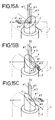
- FIG. 15A when the mirror surface 4 poses an illustrated attitude, with a shorter diameter of an elliptic mirror surface lying along the Y axis, three laser beams #1, #2 and #3 parallel to the Z-axis and incident upon the mirror surface are reflected along the X-Y plane, producing respective scanned loci lying one upon another on the recording sheet S.
- the mirror surface 4 is rotated by 90° from the attitude shown in FIG. 15A to that of FIG. 15B, the laser beams #1, #2 and #3 are reflected along the Y-Z plane producing respective scanned loci separated from each other on the recording sheet S.
- the mirror surface 4 is further rotated by 90° from the attitude shown in FIG. 15B to that of FIG.
- the laser beams #1, #2 and #3 are again reflected along the X-Y plane, producing respective scanned loci lying one upon another on the recording sheet S.
- the laser beam #2 incident upon the mirror surface at its center of rotation has a scanned locus of a straight line on the recording sheet S, while the rest of laser beams, #1 and #3, incident upon the mirror surface at points other than its center of rotation have scanned loci varying depending on the attitude of the mirror surface 4, resulting in curved lines.
- a hologram for adjusting deflection angles depending on incident positions of the laser beams is interposed between laser beam sources and an optical scanning device, the hologram rotating together with the rotation of the optical scanning device, thereby adjusting the incident positions of the laser beams upon the optical scanning device to make the scanned loci straight lines on the recording sheet (Japanese Laid-Open Patent Publication No. 4-73829).
- P- and S-polarized laser beams are generated.
- One laser beam is led to a recording sheet via a polarizing beam splitter which is rotating.
- the other laser beam separated by the polarizing beam splitter is led to the recording sheet via a reflecting surface which is rotating (Japanese Laid-Open Patent Publication No. 5-27188).
- P- and S-polarized laser beams are respectively modulated according to image information.
- One laser beam is then led to a recording sheet via a hologon (a holographic diffraction grating) which is rotating, and the other laser beam is led to the recording sheet via the hologon and a mirror whose angle is controlled by a piezoelectric device in accordance with the rotational angle of the hologon, thereby to maintain proper interval between the two laser beams on the recording sheet
- a hologon a holographic diffraction grating
- a light scanner which leads laser beams onto a recording sheet after reflecting the laser beams three times, thereby to cancel twists between the laser beams
- a rotating light optical scanning device having a transparent layer on a reflecting surface is provided, and a plurality of laser beams having different wave lengths are respectively led to the rotating light optical scanning device.
- the laser beams are separated from each other owing to the difference in diffractive indexes between them and led to a recording sheet (Japanese Laid-Open Patent Publication Nos. 4-348311 and 6-95016).
- the present invention has been made to solve the above problems. Therefore, it is an object of the invention to provide an apparatus for recording images on a recording sheet held on an interior surface of a cylinder, in which a plurality of laser beams are accurately led to the recording sheet to attain a high speed recording without introducing any rotating component other than an optical scanning device.
- an apparatus comprises light beam generating means for generating a plurality of light beams, scanning means disposed on the central axis of the cylinder and rotated thereabout comprising a mirror surface inclined with respect to the central axis of the cylinder along which the light beams are incident upon the mirror surface for scanning the recording sheet with respective light beams reflected by the mirror surface, light beam deflecting means for deflecting light beams selected from the plurality of light beams off the central axis of the cylinder to give each of the selected light beams an angle of incidence upon the mirror surface necessary in order for the plurality of light beams reflected by the mirror surface to be separated at a predetermined interval from each other on the recording sheet, and control means for controlling the direction and amount in which each of the selected light beams is deflected by the light beam deflecting means in synchronism with the rotation of the scanning means.
- the selected light beams may be other than the light beam incident upon the mirror surface at its center of rotation.
- the light beam deflecting means may deflect the selected light beams back and forth in synchronism with the rotation of the optical scanning device under the control of the control means, in a plane including each of selected light beams therein and lying parallel to another at a given distance.
- the light beam deflecting means may comprise first and second light beam deflecting devices for deflecting each of the selected light beams in a first direction and synchronizedly in a second direction perpendicular to the first direction under the control of the control means, in which each of the selected light beams deflected by the light beam deflecting means draws substantially a circle on a plane perpendicular to the central axis of the cylinder, with the center of the circle being at a point where the central axis of the cylinder crosses that plane.
- the light beam incident upon the mirror surface at its center of rotation (a central light beam) is always reflected at the point of incidence, while a light beam other than the central light beam (a selected light beam) is deflected by the light beam deflecting means to alter its angle of incidence upon the mirror surface depending on the rotational position of the mirror surface, thereby to maintain the scanned loci of the reflected light beams on the recording sheet parallel to each other at a predetermined interval.
- deflecting the selected light beam proposed in the present invention: firstly, deflecting the selected light beam back and forth in one direction (in the direction of X-axis) in a plane including the selected light beam and lying parallel to another at a distance; and secondly, deflecting the selected light beam simultaneously in two directions perpendicular to each other (a combined movement along X- and Y-axes) by the use of two light beam deflecting devices, thereby causing respective light beams to gyrate along a conical plane whose central axis is that of the cylinder.
- the light beams reflected by the mirror surface hit the recording sheet unevenly at different scanning positions for a certain rotational position of the mirror surface, resulting in different lengths for respective scanned loci.
- the second way of deflecting the light beams in contrast, it is possible to obtain reflected light beams which always hit the recording sheet evenly without any adjustment.
- the scanning means is the only rotational component included in the apparatus according to the invention, it is possible to keep its operational accuracy without any mechanical adjustment, making the apparatus compact in size. Since the lengths of respective scanned loci on the recording sheet are adjustable by controlling the starting and ending points of the scanned loci electrically, accurate recording of images can be realized.
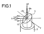
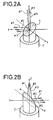
- FIGS. 1, 2A and 2B schematically explain the principle upon which a first embodiment of the present invention is based.
- a laser beam L0 incident upon the center of the mirror surface 4 is reflected along X-axis.
- the reflection path of the laser beam L0 reflected on the mirror surface 4 is shifted in the X-Z plane by - ⁇ Z along Z-axis.
- the reflection path of the laser beam L0 is shifted in the X-Z plane by + ⁇ z along Z-axis.
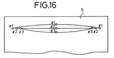
- three laser beams #1, #2 and #3 parallel to each other are introduced to the optical scanning device 2 along Z axis.
- the laser beam #2 is introduced to the optical scanning device 2 at its center of rotation, and laser beams #1 and #3 are respectively apart from the laser beam #2 by a predetermined distance in the direction of Y-axis.
- By deflecting the laser beams #1 and #3 by a certain angle in the negative and positive directions respectively along X-axis it is possible to shift the reflection paths thereof in the positive and negative directions along Z-axis by a certain amount, respectively. Accordingly, since the reflection paths of the laser beams #1 and #3 which have been included in the X-Y plane as shown in FIG.
- each spot of the laser beams #1, #2 and #3 incident upon the mirror surface 4 is projected on a conjugate plane S' of the recording sheet S
- each spot of the laser beams #1 and #3 on the conjugate plane S' makes a simple harmonic motion as shown in FIG. 4 which is represented by the following formulas, in which ⁇ is the angular velocity of the optical scanning device 2:
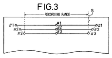
- a plurality of scanned loci parallel to and apart from each other at a given interval, as shown in FIG. 3 can be formed on the recording sheet, by deflecting the laser beams #1 and #3 according to the above formulas and introducing them to the optical scanning device 2.
- FIG. 5 shows an apparatus for putting into operation the principle described above on which the first embodiment of the present invention is based.
- the apparatus shown in FIG. 5 comprises a laser beam generator 6 for generating a laser beam L, a beam splitter 8 for splitting the generated laser beam L into three laser beams #1, #2 and #3, an acousto-optical device 10X for deflecting the laser beam #1 in the direction of X-axis shown in FIG.
- an acousto-optical device 12 for modulating the laser beam #2 according to the image information without deflecting it
- an acousto-optical device 14X for deflecting the laser beam #3 in the direction of the X-axis and modulate it according to the image information
- mirrors 16, 18 and 20 for reflecting the laser beams #1, #2 and #3, respectively
- a condenser lens 22 for condensing the laser beams #1, #2 and #3
- an optical scanning device 2 having a rotating mirror surface 4 for reflecting and leading the laser beams #1, #2 and #3 to a recording sheet S.
- the recording sheet S is held on an interior surface of a cylindrical drum 24, and the optical scanning device 2 is disposed on the central axis of the drum 24.
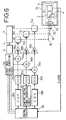
- FIG. 6 shows a circuit for controlling the acousto-optical devices 10X, 12 and 14X.
- Scanned loci, on the recording sheet S, produced by the laser beams #1, #2 and #3 deflected by the acousto-optical devices 10X, 12, 14X and reflected by the mirror surface 4 have different scanning lengths respectively in the direction of a main scanning direction (shown by the arrow x in FIG. 5).
- a control clock signal generating circuit 40 shown in FIG. 7 is provided in the control circuit 26.
- the control clock signal generating circuit 40 comprises a phase locking loop (PLL) circuit 42 for generating a phase sync signal based on a rotational position signal P supplied from the unillustrated encoder provided in the optical scanning device 2, a base clock signal generating circuit 44 for generating a base clock signal B from the phase sync signal based on a main scan starting signal LSYNC supplied by the encoder, a counter 46 for counting the number of the base clock signals, a look-up table 48 which outputs a delay amount setting signal for setting delay amount for each of the control clock signals CL1, CL2, CL3 to control the laser beams #1, #2 and #3 based on the count in the counter 46, and delay circuits 50a, 50b, 50c for generating the control clock signals CL1, CL2, CL3 from the base clock signal by delaying it by necessary delay amounts, respectively.
- the control clock signals CL1, CL2, CL3 are fed to the binary image signal generating circuit 38 shown in FIG. 6.
- the laser beam L outputted from the laser beam generator 6 is splitted into three laser beams #1, #2, #3.
- the laser beam #1 is deflected by the acousto-optical device 10X in the direction of X-axis (see FIGS. 2A, 2B), and simultaneously on/ off controlled according to the image information.
- the laser beam #1 is led to the optical scanning device 2 through the condenser lens 22.
- the optical scanning device 2 reflects the laser beam #1 on the mirror surface 4 rotating about the central axis of the drum 24 and leads it onto the recording sheet S.
- the laser beam #3 is also led onto the recording sheet S through the acousto-optical device 14X, the mirror 20, the condenser lens 22 and the optical scanning device 2.
- the laser beam #2 incident upon the mirror surface 4 at its center of rotation is led onto the recording sheet S, after on/off controlled by the acousto-optical device 12 according to the image information without being deflected, through the mirror 18, condenser lens 22 and the optical scanning device 2.
- An image is formed on the recording sheet S with three scanned loci of the three laser beams which run parallel to each other with a given interval therebetween.
- the control circuit 26 supplies the control clock signals to the cosine-wave signal generating circuits 28a, 28b based on the rotational position signal P supplied by the unillustrated encoder provided in the optical scanning device 2 and the main scan starting signal LSYNC.
- the voltage-controlled oscillators 32a, 32c convert the cosine-wave voltage signals into frequency-modulated signals, and the converted frequency-modulated signals are supplied to the acousto-optical devices 10X, 14X via the amplifiers 36a, 36c, after on/off controlled by the modulators 34a, 34c according to the binary image signal.
- the acousto-optical devices 10X, 14X respectively deflect the laser beams #1 and #3 in the direction of X-axis based on the frequency-modulated signals.
- the control circuit 26 also supplies one of the control clock signals to the constant-voltage signal generating circuit 30, and the generated constant-voltage signal is supplied to the voltage-controlled oscillator 32b, which converts the constant-voltage signal into the frequency-modulated signal.
- the frequency-modulated signal is supplied to the acousto-optical device 12 through the amplifier 36b, after being on/off controlled by the modulator 34b according to the binary image signal.
- the acousto-optical device 12 only on/off controls the laser beam #2 without deflecting it.
- the laser beam #1 led to the mirror surface 4 of the optical scanning device 2 makes a simple harmonic motion along X-axis in synchronism with the rotation of the optical scanning device 2.
- the laser beam #3 also makes another simple harmonic motion off-phase by 180° from that of the laser beam #1 as shown in FIG. 4B.
- the laser beam #2 is led to the recording sheet S after only being on/off controlled without making a simple harmonic motion.
- the laser beams #1, #2 and #3 controlled to maintain a given interval between them are led to the recording sheet S and an image is recorded thereon. The interval may be easily controlled by the amplification factors set for the amplifiers 36a, 36b, 36c.
- respective scanned loci of the laser beams #1, #2 and #3 have starting and ending points different from each other, resulting in different scanning lengths, when the laser beams #1 and #3 are controlled to be deflected in the direction of X-axis only, and there arises a fear that distortion in the recorded image becomes visually recognizable when the difference in the scanning lengths is large.
- the above problem can be solved by adjusting the timing at which the binary image signal is supplied to the modulators 34a, 34b, 34c, under the control by the control clock signals CL1, CL2, CL3 generated by the control clock signal generating circuit 40.
- the rotational position signal P supplied by the unillustrated encoder provided in the optical scanning device 2 is controlled its phase by the PLL circuit 42, and a phase sync signal is generated therefrom.
- the phase sync signal is supplied to the base clock signal generating circuit 44 to generate a base clock signal B under the control of the main scan starting signal LSYNC, as shown in FIG. 8.
- the base clock signal B is counted its number by the counter 46 and supplied to the delay circuits 50a, 50b, 50c which are described below.
- the count of the base clock signal B at the counter 46 is supplied to the look-up table 48.
- the look-up table 48 supplies the delay amount setting signals having been set beforehand to respective delay circuits 50a, 50b, 50c in response to the count given by the counter 46 which correspond to the scanning positions of the laser beams #1, #2, #3 on the recording sheet S.
- the delay circuits 50a, 50b, 50c produce the control clock signals CL1, CL2, CL3, respectively, by delaying the base clock signal by respective delay amounts in response to the delay amount setting signals.
- the control clock signals CL1, CL2, CL3 are fed to the binary image signal generating circuit 38.
- the control clock signal CL1 controls the timing in which the binary image signal is outputted to be recorded by the laser beam #1.
- the delay circuit 50a delays a start of recording the binary image signal by a period Td1 behind a main scan starting time of the base clock signal B in response to the delay amount setting signal supplied from the look-up table 48, and sets an end of recording the binary image signal at a main scan finishing time (m-th clock pulse) of the base clock signal B.
- the pulse intervals in the control clock signal CL1 are set to be as uniform as possible based on the delay amount setting signal supplied from the look-up table 48.
- the control clock signal CL2 controls the timing in which the binary image signal is outputted to be recorded by the laser beam #2.
- the delay circuit 50b delays a start of recording the binary image signal by a period Td2 behind the main scan starting time of the base clock signal B in response to the delay amount setting signal, and delays an end of recording the binary image signal by a period Td2 behind the main scan finishing time (m-th clock pulse) of the base clock signal B.
- the pulse intervals in the control clock signal CL2 are set to be as uniform as possible based on the delay amount setting signal.
- the control clock signal CL3 controls the timing in which the binary image signal is outputted to be recorded by the laser beam #3.
- the delay circuit 50c delays a start of recording the binary image signal by a period Td3 behind the main scan starting time of the base clock signal B in response to the delay amount setting signal, and delays an end of recording the binary image signal by a period Td3 behind the main scan finishing time (m-th clock pulse) of the base clock signal B.
- the pulse intervals in the control clock signal CL3 are set to be as uniform as possible based on the delay amount setting signal.
- the control clock signals CL1, CL2, CL3, produced as described above, are supplied to the binary image signal generating circuit 38.
- the binary image signal generating circuit 38 outputs the binary image signals to the modulators 34a, 34b, 34c at the timing shown in FIG. 8.
- the laser beams #1 and #2 modulated by respective binary image signals record an image on the recording sheet in the same range as the laser beam #3 records the image. Accordingly, an accurate image free from distortion can be formed by the scan lines each having the same recording range in the main scanning direction.
- the difference between the lengths of scan lines produced by the laser beams #1, #2 and #3 is overcome by adjusting the timing of recording by respective scan lines.
- scan lines inherently having constant length and interval may be utilized.
- those parts identical to those of the first embodiment are denoted identically, and detailed description thereof is omitted.
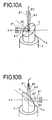
- FIGS. 9A-9C, 10A and 10B schematically explain the principle upon which a second embodiment of the present invention is based.
- the reflection path of the laser beam L0 is shifted in the X-Y plane by - ⁇ Y along Y-axis. Therefore, it is possible to shift the reflection path of the laser beam L0 two-dimensionally on the recording sheet S, by deflecting the laser beam L0 by ⁇ xy with respect to Z axis in the directions of X- and Y-axis simultaneously. Accordingly, by deflecting the laser beam #1 in the negative direction of X-axis and the positive direction of Y-axis simultaneously, and the laser beam #3 in the positive direction of X-axis and the negative direction of Y-axis simultaneously, it is possible to rearrange the reflection paths of the laser beams #1, #2 and #3 to lie in the X-Z plane as shown in FIG.
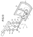
- FIG. 13 shows an apparatus for putting into operation the principle described above on which the second embodiment of the present invention is based.
- the apparatus shown in FIG. 13 comprises an acousto-optical device 10X for deflecting the laser beam #1 in the direction of X-axis of the optical scanning device 2 as shown in FIGS.
- an acousto-optical device 10Y for deflecting the laser beam #1 in the direction of Y-axis and modulate it according to image information
- an acousto-optical device 12 for modulating the laser beam #2 according to the image information without deflecting it
- an acousto-optical device 14X for deflecting the laser beam #3 in the direction of the X-axis
- an acousto-optical device 14Y for deflecting the laser beam #3 in the direction of the Y-axis and modulate it according to the image information.
- Constitution other than the above is identical to that of the first embodiment shown in FIG. 5.
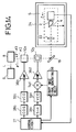
- FIG. 14 is a diagram of a circuit for controlling the acousto-optical devices 10X and 10Y shown in FIG. 13.
- the laser beam L outputted from the laser beam generator 6 is splitted into three laser beams #1, #2, #3.
- the laser beam #1 is deflected by the acousto-optical device 10Y in the direction of Y-axis and simultaneously on/off controlled according to image information, after being deflected by the acousto-optical device 10X in the direction of X-axis (see FIGS. 10A, 10B).
- the laser beam #1 is led to the optical scanning device 2 through the condenser lens 22, after being reflected by the mirror 16.
- the optical scanning device 2 reflects the laser beam #1 on the mirror surface 4 rotating about the central axis of the drum 24 and leads it onto the recording sheet S.
- the laser beam #3 is also led onto the recording sheet S through the acousto-optical devices 14X and 14Y, the mirror 20, the condenser lens 22 and the optical scanning device 2.
- the laser beam #2 incident upon the mirror surface 4 at its center of rotation is led onto the recording sheet S through the mirror 18, condenser lens 22 and the optical scanning device 2, after on/off controlled by the acousto-optical device 12 according to the image information, without being deflected.
- an image is formed on the recording sheet S by three scanned loci of the laser beams which run parallel to each other with a given interval therebetween and having the lengths equal to each other.
- the control circuit 27 supplies one of the control clock signals to the cosine-wave signal generating circuit 28a in response to the rotational position signal supplied by the unillustrated encoder provided in the optical scanning device 2.
- the acousto-optical devices 10X deflects the laser beam #1 in the direction of X-axis based on the cosine-wave voltage signal, as shown in FIGS. 10A, 10B.
- the control circuit 27 also supplies another control clock signal to the sine-wave signal generating circuit 28c.
- the frequency modulated and on/off controlled signal is supplied to the acousto-optical device 10Y via the amplifier 36d.
- the acousto-optical device 10Y deflects the laser beam #1 which is deflected in the direction of X-axis by the acousto-optical device 10X further in the direction of Y-axis based on the sine-wave voltage signal, as shown in FIGS. 10A, 10B.
- the laser beam #1 led to the mirror surface 4 of the optical scanning device 2 draws substantially a circle on a plane S' perpendicular to the rotational axis of the optical scanning device 2 in synchronism with the rotation thereof.
- the drawn circle is not necessarily a complete round when correction signals for correcting the distortion or aberation in the optical system is added, as described below.
- the laser beam #3 also draws substantially a circle off-phase by 180° from that of the laser beam #1 on the plane S' as shown in FIGS. 12A and 12B.
- the laser beam #2 is led to the recording sheet S without making any motion on the plane S' after only being on/off controlled.
- the laser beams #1, #2 and #3 controlled to maintain a given interval between them are led to the recording sheet S and an image is recorded thereon. The interval may be easily controlled by the amplification factors set for the amplifiers 36a and 36d.
- the acousto-optical devices 10X and 10Y are constructed separately. However, it is possible to construct them in one body, thereby to deflect the laser beam in both X- and Y-directions and modulate it according to the image information with one acousto-optical device.
- the acousto-optical device can be replaced with an electro-optical device. Further, more than four laser beams may be used to record images.
- the beam splitter 8 may be dispensed with by using separate laser beam generators which generate laser beams #1, #2 and #3 independently.
- correction signals By adding correction signals to the cosine-wave signal generators 28a, 28b or the sine-wave signal generator 28c, it is possible to realize an apparatus in which aberation in the condenser lens 22, distortion in the mirror surface 4, wobbling of the rotation axis of the mirror, distorted scanned loci due to laser beams #1, #2 or #3 incident askew or displaced (offset) upon the mirror surface 4, and so on, are corrected.
Landscapes
- Engineering & Computer Science (AREA)
- Multimedia (AREA)
- Signal Processing (AREA)
- Physics & Mathematics (AREA)
- General Physics & Mathematics (AREA)
- Optics & Photonics (AREA)
- Facsimile Scanning Arrangements (AREA)
- Mechanical Optical Scanning Systems (AREA)
Applications Claiming Priority (9)
| Application Number | Priority Date | Filing Date | Title |
|---|---|---|---|
| JP21376394 | 1994-09-07 | ||
| JP213763/94 | 1994-09-07 | ||
| JP21377294 | 1994-09-07 | ||
| JP21377294 | 1994-09-07 | ||
| JP21376394 | 1994-09-07 | ||
| JP213772/94 | 1994-09-07 | ||
| JP113328/95 | 1995-05-11 | ||
| JP11332895A JP3667816B2 (ja) | 1994-09-07 | 1995-05-11 | 円筒内面走査型画像記録装置 |
| JP11332895 | 1995-05-11 |
Publications (3)
| Publication Number | Publication Date |
|---|---|
| EP0701158A2 true EP0701158A2 (de) | 1996-03-13 |
| EP0701158A3 EP0701158A3 (de) | 1998-04-15 |
| EP0701158B1 EP0701158B1 (de) | 2002-09-11 |
Family
ID=27312486
Family Applications (1)
| Application Number | Title | Priority Date | Filing Date |
|---|---|---|---|
| EP95109944A Expired - Lifetime EP0701158B1 (de) | 1994-09-07 | 1995-06-26 | Gerät zur Aufzeichnung von Bildern auf der Innenfläche eines Zylinders |
Country Status (4)
| Country | Link |
|---|---|
| US (1) | US5502709A (de) |
| EP (1) | EP0701158B1 (de) |
| JP (1) | JP3667816B2 (de) |
| DE (1) | DE69528127T2 (de) |
Cited By (4)
| Publication number | Priority date | Publication date | Assignee | Title |
|---|---|---|---|---|
| EP0828177A3 (de) * | 1996-09-06 | 1998-12-02 | Fuji Photo Film Co., Ltd. | Akustooptisches Bauelement, Lichtablenker, Lichtstrahlabtastvorrichtung und Bildaufzeichnungsvorrichtung |
| EP0827325A3 (de) * | 1996-08-30 | 1999-10-20 | Bayer Corporation | Mehrstrahlabtaster mit akusto-optischem Element zur Abtastung von Bildaufzeichnungsoberflächen |
| EP0822700A3 (de) * | 1996-07-29 | 1999-10-20 | Bayer Corporation | Strahlfehlerkorrektur unter Verwendung eines bewegbaren Korrekturelements |
| EP1168812A3 (de) * | 2000-06-26 | 2003-07-09 | Fuji Photo Film Co., Ltd. | Gerät zur Bildaufzeichnung durch Abtastung von Innenflächen |
Families Citing this family (11)
| Publication number | Priority date | Publication date | Assignee | Title |
|---|---|---|---|---|
| GB9516771D0 (en) * | 1995-08-16 | 1995-10-18 | Crosfield Electronics Ltd | Output scanner |
| US5764381A (en) * | 1996-07-10 | 1998-06-09 | Scitex Corporation Ltd. | Internal drum recorder with array imaging |
| US5864418A (en) * | 1996-08-30 | 1999-01-26 | Bayer Corporation Agfa Division | Multi-beam scanner with mechanically moving element for scanning imaging surfaces |
| EP1571824B1 (de) | 1996-10-30 | 2012-10-24 | FUJIFILM Corporation | Gerät und Verfahren zum mehrstrahligem Abtasten einer Innenfläche |
| US5892610A (en) * | 1997-07-10 | 1999-04-06 | Agfa Division--Bayer Corporation | Scanning system with error-correcting deflector |
| EP1046941B1 (de) * | 1999-04-21 | 2005-06-29 | Fuji Photo Film Co., Ltd. | Verfahren zur Korrektur der Lage eines Lichtbündels in einem Abtastgerät |
| US6396042B1 (en) * | 1999-10-19 | 2002-05-28 | Raytheon Company | Digital laser image recorder including delay lines |
| GB0009134D0 (en) * | 2000-04-13 | 2000-05-31 | Fujifilm Electronic Imaging Li | AOM compensation using PWM |
| KR100357606B1 (ko) * | 2000-11-15 | 2002-10-25 | 현대자동차주식회사 | 원통체의 내표면 영상 스캐닝 시스템 |
| US7250961B2 (en) | 2001-08-22 | 2007-07-31 | Fujifilm Corporation | Light beam scanning method and apparatus compensating for defects |
| US6825868B2 (en) * | 2002-12-12 | 2004-11-30 | Fujifilm Electronic Imaging Limited | Radiation image data recording method employing a rotating reflector and multiple radiation beams |
Citations (8)
| Publication number | Priority date | Publication date | Assignee | Title |
|---|---|---|---|---|
| JPH0473829A (ja) | 1990-07-12 | 1992-03-09 | Fujitsu Ltd | 薄型キーボード |
| US5097351A (en) | 1990-08-06 | 1992-03-17 | Holotek, Ltd. | Simultaneous multibeam scanning system |
| JPH04348311A (ja) | 1991-02-04 | 1992-12-03 | Ricoh Co Ltd | 光走査装置 |
| JPH0527188A (ja) | 1990-11-26 | 1993-02-05 | Dainippon Screen Mfg Co Ltd | 円筒内面走査型画像記録装置 |
| JPH0527190A (ja) | 1991-07-18 | 1993-02-05 | Dainippon Screen Mfg Co Ltd | 円筒内面走査型画像記録装置 |
| JPH05289018A (ja) | 1992-04-14 | 1993-11-05 | Fuji Photo Film Co Ltd | インナードラム走査型記録装置 |
| JPH05308488A (ja) | 1992-01-12 | 1993-11-19 | Scitex Corp Ltd | 走査装置及び走査方法 |
| JPH0695016A (ja) | 1992-09-09 | 1994-04-08 | Brother Ind Ltd | 光走査装置 |
Family Cites Families (7)
| Publication number | Priority date | Publication date | Assignee | Title |
|---|---|---|---|---|
| JPS5586265A (en) * | 1978-12-23 | 1980-06-28 | Fuji Photo Film Co Ltd | Recorder |
| IL80241A (en) * | 1986-10-07 | 1991-03-10 | Scitex Corp Ltd | Internal drum plotter |
| US5026133A (en) * | 1990-05-01 | 1991-06-25 | Torii Winding Machine Co., Ltd. | Large format laser scanner with wavelength insensitive scanning mechanism |
| US5214528A (en) * | 1990-09-14 | 1993-05-25 | Konica Corporation | Optical beam scanning apparatus |
| DE69123937T2 (de) * | 1990-10-31 | 1997-07-31 | Dainippon Screen Mfg | Gerät zum Abtasten einer inneren Trommelfläche und zugehöriges Abtastverfahren |
| JP2918366B2 (ja) * | 1991-09-04 | 1999-07-12 | 大日本スクリーン製造株式会社 | 円筒内面走査型画像記録装置 |
| JP3239188B2 (ja) * | 1992-02-28 | 2001-12-17 | コニカ株式会社 | 光ビーム走査装置 |
-
1995
- 1995-05-11 JP JP11332895A patent/JP3667816B2/ja not_active Expired - Fee Related
- 1995-06-06 US US08/470,119 patent/US5502709A/en not_active Expired - Lifetime
- 1995-06-26 DE DE69528127T patent/DE69528127T2/de not_active Expired - Fee Related
- 1995-06-26 EP EP95109944A patent/EP0701158B1/de not_active Expired - Lifetime
Patent Citations (8)
| Publication number | Priority date | Publication date | Assignee | Title |
|---|---|---|---|---|
| JPH0473829A (ja) | 1990-07-12 | 1992-03-09 | Fujitsu Ltd | 薄型キーボード |
| US5097351A (en) | 1990-08-06 | 1992-03-17 | Holotek, Ltd. | Simultaneous multibeam scanning system |
| JPH0527188A (ja) | 1990-11-26 | 1993-02-05 | Dainippon Screen Mfg Co Ltd | 円筒内面走査型画像記録装置 |
| JPH04348311A (ja) | 1991-02-04 | 1992-12-03 | Ricoh Co Ltd | 光走査装置 |
| JPH0527190A (ja) | 1991-07-18 | 1993-02-05 | Dainippon Screen Mfg Co Ltd | 円筒内面走査型画像記録装置 |
| JPH05308488A (ja) | 1992-01-12 | 1993-11-19 | Scitex Corp Ltd | 走査装置及び走査方法 |
| JPH05289018A (ja) | 1992-04-14 | 1993-11-05 | Fuji Photo Film Co Ltd | インナードラム走査型記録装置 |
| JPH0695016A (ja) | 1992-09-09 | 1994-04-08 | Brother Ind Ltd | 光走査装置 |
Cited By (6)
| Publication number | Priority date | Publication date | Assignee | Title |
|---|---|---|---|---|
| EP0822700A3 (de) * | 1996-07-29 | 1999-10-20 | Bayer Corporation | Strahlfehlerkorrektur unter Verwendung eines bewegbaren Korrekturelements |
| EP0827325A3 (de) * | 1996-08-30 | 1999-10-20 | Bayer Corporation | Mehrstrahlabtaster mit akusto-optischem Element zur Abtastung von Bildaufzeichnungsoberflächen |
| EP0828177A3 (de) * | 1996-09-06 | 1998-12-02 | Fuji Photo Film Co., Ltd. | Akustooptisches Bauelement, Lichtablenker, Lichtstrahlabtastvorrichtung und Bildaufzeichnungsvorrichtung |
| US5907428A (en) * | 1996-09-06 | 1999-05-25 | Fuji Photo Film Co., Ltd. | Acousto-optic element light deflector light beam scanning apparatus and image recording apparatus |
| EP1168812A3 (de) * | 2000-06-26 | 2003-07-09 | Fuji Photo Film Co., Ltd. | Gerät zur Bildaufzeichnung durch Abtastung von Innenflächen |
| US6677578B2 (en) | 2000-06-26 | 2004-01-13 | Fuji Photo Film Co., Ltd. | Internal-surface-scanning image recording apparatus |
Also Published As
| Publication number | Publication date |
|---|---|
| US5502709A (en) | 1996-03-26 |
| EP0701158B1 (de) | 2002-09-11 |
| JPH08130612A (ja) | 1996-05-21 |
| DE69528127D1 (de) | 2002-10-17 |
| JP3667816B2 (ja) | 2005-07-06 |
| EP0701158A3 (de) | 1998-04-15 |
| DE69528127T2 (de) | 2003-01-02 |
Similar Documents
| Publication | Publication Date | Title |
|---|---|---|
| EP0701158B1 (de) | Gerät zur Aufzeichnung von Bildern auf der Innenfläche eines Zylinders | |
| US5097351A (en) | Simultaneous multibeam scanning system | |
| US5309178A (en) | Laser marking apparatus including an acoustic modulator | |
| US4661699A (en) | Scanning beam control system and method with bi-directional reference scale | |
| US5179463A (en) | Simultaneous multibeam scanning system | |
| US5923461A (en) | Scanner with deflection element for scanning imaging surfaces | |
| JPH0527086B2 (de) | ||
| EP0288970B1 (de) | Optisches System für ein Lichtpunktabtastsystem | |
| IL80242A (en) | Laser scanner | |
| EP0324364B1 (de) | Optisches Gerät mit Laser | |
| US5907428A (en) | Acousto-optic element light deflector light beam scanning apparatus and image recording apparatus | |
| EP0840493B1 (de) | Gerät und Verfahren zum mehrstrahligen Abtasten einer Innenfläche | |
| EP0847185B1 (de) | Lichtstrahlabtastgerät und Steuerverfahren dafür | |
| US4578577A (en) | Light beam scanning device | |
| US4641950A (en) | Exposure system | |
| US5864418A (en) | Multi-beam scanner with mechanically moving element for scanning imaging surfaces | |
| JP4081474B2 (ja) | 円筒内面走査型画像記録装置 | |
| JPH06503454A (ja) | 平行移動基準目盛を有する走査ビーム制御装置 | |
| JP3581503B2 (ja) | 内面走査型光ビーム走査装置およびその制御方法 | |
| JP4054078B2 (ja) | 音響光学機器、光ビーム走査装置、及び音響光学素子の姿勢調整方法 | |
| US6677578B2 (en) | Internal-surface-scanning image recording apparatus | |
| JPS6031295B2 (ja) | レ−ザコム装置 | |
| JPS5942855B2 (ja) | 複数ビ−ム同時走査装置 | |
| JP3655416B2 (ja) | 内面走査型光ビーム走査装置の制御方法 | |
| JPH1020223A (ja) | 円筒内面走査型画像記録装置 |
Legal Events
| Date | Code | Title | Description |
|---|---|---|---|
| PUAI | Public reference made under article 153(3) epc to a published international application that has entered the european phase |
Free format text: ORIGINAL CODE: 0009012 |
|
| AK | Designated contracting states |
Kind code of ref document: A2 Designated state(s): DE FR GB |
|
| PUAL | Search report despatched |
Free format text: ORIGINAL CODE: 0009013 |
|
| AK | Designated contracting states |
Kind code of ref document: A3 Designated state(s): DE FR GB |
|
| 17P | Request for examination filed |
Effective date: 19980526 |
|
| 17Q | First examination report despatched |
Effective date: 19990412 |
|
| GRAG | Despatch of communication of intention to grant |
Free format text: ORIGINAL CODE: EPIDOS AGRA |
|
| GRAG | Despatch of communication of intention to grant |
Free format text: ORIGINAL CODE: EPIDOS AGRA |
|
| GRAH | Despatch of communication of intention to grant a patent |
Free format text: ORIGINAL CODE: EPIDOS IGRA |
|
| GRAH | Despatch of communication of intention to grant a patent |
Free format text: ORIGINAL CODE: EPIDOS IGRA |
|
| GRAA | (expected) grant |
Free format text: ORIGINAL CODE: 0009210 |
|
| AK | Designated contracting states |
Kind code of ref document: B1 Designated state(s): DE FR GB |
|
| REG | Reference to a national code |
Ref country code: GB Ref legal event code: FG4D |
|
| REF | Corresponds to: |
Ref document number: 69528127 Country of ref document: DE Date of ref document: 20021017 |
|
| ET | Fr: translation filed | ||
| PLBE | No opposition filed within time limit |
Free format text: ORIGINAL CODE: 0009261 |
|
| STAA | Information on the status of an ep patent application or granted ep patent |
Free format text: STATUS: NO OPPOSITION FILED WITHIN TIME LIMIT |
|
| 26N | No opposition filed |
Effective date: 20030612 |
|
| REG | Reference to a national code |
Ref country code: GB Ref legal event code: 732E |
|
| REG | Reference to a national code |
Ref country code: FR Ref legal event code: TP Ref country code: FR Ref legal event code: CD |
|
| PGFP | Annual fee paid to national office [announced via postgrant information from national office to epo] |
Ref country code: GB Payment date: 20090624 Year of fee payment: 15 Ref country code: DE Payment date: 20090604 Year of fee payment: 15 |
|
| REG | Reference to a national code |
Ref country code: FR Ref legal event code: ST Effective date: 20100226 |
|
| PG25 | Lapsed in a contracting state [announced via postgrant information from national office to epo] |
Ref country code: FR Free format text: LAPSE BECAUSE OF NON-PAYMENT OF DUE FEES Effective date: 20090630 |
|
| PGFP | Annual fee paid to national office [announced via postgrant information from national office to epo] |
Ref country code: FR Payment date: 20100901 Year of fee payment: 15 |
|
| REG | Reference to a national code |
Ref country code: FR Ref legal event code: D3 |
|
| PGRI | Patent reinstated in contracting state [announced from national office to epo] |
Ref country code: FR Effective date: 20101103 |
|
| GBPC | Gb: european patent ceased through non-payment of renewal fee |
Effective date: 20100626 |
|
| REG | Reference to a national code |
Ref country code: FR Ref legal event code: ST Effective date: 20110228 |
|
| PG25 | Lapsed in a contracting state [announced via postgrant information from national office to epo] |
Ref country code: DE Free format text: LAPSE BECAUSE OF NON-PAYMENT OF DUE FEES Effective date: 20110101 |
|
| PGRI | Patent reinstated in contracting state [announced from national office to epo] |
Ref country code: FR Effective date: 20101103 |
|
| PG25 | Lapsed in a contracting state [announced via postgrant information from national office to epo] |
Ref country code: GB Free format text: LAPSE BECAUSE OF NON-PAYMENT OF DUE FEES Effective date: 20100626 |