EP0701232B1 - Système de télévision à circuit fermé à caméra mobile et acquisition automatique de cible - Google Patents
Système de télévision à circuit fermé à caméra mobile et acquisition automatique de cible Download PDFInfo
- Publication number
- EP0701232B1 EP0701232B1 EP95112903A EP95112903A EP0701232B1 EP 0701232 B1 EP0701232 B1 EP 0701232B1 EP 95112903 A EP95112903 A EP 95112903A EP 95112903 A EP95112903 A EP 95112903A EP 0701232 B1 EP0701232 B1 EP 0701232B1
- Authority
- EP
- European Patent Office
- Prior art keywords
- camera
- carriage
- target object
- positions
- along
- Prior art date
- Legal status (The legal status is an assumption and is not a legal conclusion. Google has not performed a legal analysis and makes no representation as to the accuracy of the status listed.)
- Expired - Lifetime
Links
Images


Classifications
-
- G—PHYSICS
- G08—SIGNALLING
- G08B—SIGNALLING SYSTEMS, e.g. PERSONAL CALLING SYSTEMS; ORDER TELEGRAPHS; ALARM SYSTEMS
- G08B13/00—Burglar, theft or intruder alarms
- G08B13/18—Actuation by interference with heat, light, or radiation of shorter wavelength; Actuation by intruding sources of heat, light, or radiation of shorter wavelength
- G08B13/189—Actuation by interference with heat, light, or radiation of shorter wavelength; Actuation by intruding sources of heat, light, or radiation of shorter wavelength using passive radiation detection systems
- G08B13/194—Actuation by interference with heat, light, or radiation of shorter wavelength; Actuation by intruding sources of heat, light, or radiation of shorter wavelength using passive radiation detection systems using image scanning and comparing systems
- G08B13/196—Actuation by interference with heat, light, or radiation of shorter wavelength; Actuation by intruding sources of heat, light, or radiation of shorter wavelength using passive radiation detection systems using image scanning and comparing systems using television cameras
- G08B13/19678—User interface
- G08B13/19689—Remote control of cameras, e.g. remote orientation or image zooming control for a PTZ camera
-
- G—PHYSICS
- G08—SIGNALLING
- G08B—SIGNALLING SYSTEMS, e.g. PERSONAL CALLING SYSTEMS; ORDER TELEGRAPHS; ALARM SYSTEMS
- G08B13/00—Burglar, theft or intruder alarms
- G08B13/18—Actuation by interference with heat, light, or radiation of shorter wavelength; Actuation by intruding sources of heat, light, or radiation of shorter wavelength
- G08B13/189—Actuation by interference with heat, light, or radiation of shorter wavelength; Actuation by intruding sources of heat, light, or radiation of shorter wavelength using passive radiation detection systems
- G08B13/194—Actuation by interference with heat, light, or radiation of shorter wavelength; Actuation by intruding sources of heat, light, or radiation of shorter wavelength using passive radiation detection systems using image scanning and comparing systems
- G08B13/196—Actuation by interference with heat, light, or radiation of shorter wavelength; Actuation by intruding sources of heat, light, or radiation of shorter wavelength using passive radiation detection systems using image scanning and comparing systems using television cameras
- G08B13/19617—Surveillance camera constructional details
- G08B13/19623—Arrangements allowing camera linear motion, e.g. camera moving along a rail cable or track
-
- G—PHYSICS
- G08—SIGNALLING
- G08B—SIGNALLING SYSTEMS, e.g. PERSONAL CALLING SYSTEMS; ORDER TELEGRAPHS; ALARM SYSTEMS
- G08B13/00—Burglar, theft or intruder alarms
- G08B13/18—Actuation by interference with heat, light, or radiation of shorter wavelength; Actuation by intruding sources of heat, light, or radiation of shorter wavelength
- G08B13/189—Actuation by interference with heat, light, or radiation of shorter wavelength; Actuation by intruding sources of heat, light, or radiation of shorter wavelength using passive radiation detection systems
- G08B13/194—Actuation by interference with heat, light, or radiation of shorter wavelength; Actuation by intruding sources of heat, light, or radiation of shorter wavelength using passive radiation detection systems using image scanning and comparing systems
- G08B13/196—Actuation by interference with heat, light, or radiation of shorter wavelength; Actuation by intruding sources of heat, light, or radiation of shorter wavelength using passive radiation detection systems using image scanning and comparing systems using television cameras
- G08B13/19678—User interface
- G08B13/1968—Interfaces for setting up or customising the system
Definitions
- This invention relates generally to closed-circuit television surveillance systems and pertains more particularly to such systems in which a television camera is mounted on a carriage for movement along a rail or track, and in which the system is subject to automatic control by a computer or the like.
- a target object such as a door
- a sensor which provides an alarm signal to a central control portion of the surveillance system when the door is opened.
- the control system can implement an immediate adjustment to the camera direction, zoom condition, etc. so that an image of the door is provided by the camera within a very short time after the door is opened.
- the system utilizes a moving camera, such as a camera mounted on a carriage which travels along a rail
- the camera may be located at any arbitrary position in its range of movement at the time an alarm is received. Since the camera location at the time of the alarm cannot be known in advance, it is not possible to store in advance data defining a particular direction and zoom condition of the camera which will enable the camera to provide an image of the target from the position of the camera at the time of the alarm.
- the human operator may attempt to respond to the alarm signal by operating system controls to reposition the camera carriage and to adjust the camera direction, etc. so that an image of the target object is obtained.
- the variety of possible camera positions and directions-of-view may lead to disorientation on the part of the operator.
- the system is set up with multiple target objects (e.g., multiple doors, windows, cabinets and so forth) for which alarms may be actuated, the operator may have difficulty identifying the particular target to which the alarm pertains. As a result, the human operator's response to the alarm may be too slow to capture an image of the event (such as entry of an intruder) which caused the alarm.
- US-A-4 510 526 discloses a surveillance system wherein a TV-camera is pivotally mounted along its optical axis on or along a ceiling, and a mirror is pivotally mounted about an axis perpendicular to the optical axis to intercept the view of the camera. Then, by selected rotation of the camera and mirror about these axes, both pan and tilt functions are achieved in a very compact structure. Further this system comprises an open-door sensor which is responsive to a door being opened and provides a signal to a control console, which automatically causes a tilt signal and a pan signal to operate different motors. These motors train the camera and the door and operate the zoom-mechanism of the camera to adjust the focal lens of the camera to the desired field of view.
- the present invention has as its primary object the provision of a closed circuit television surveillance system, using a rail-based television camera, that is capable of acquiring an image of a fixed target within a minimum amount of time after receipt of an alarm signal or the like.
- Another object of the invention is provision of a surveillance system using a rail-mounted camera in which the camera is controlled to continuously track a target while the camera is moving along the rail.
- the invention provides a method of operating a rail-based closed-circuit television surveillance system wherein the system includes an elongated track positioned along a path, a carriage supported and movable along the track for transporting a television camera along the path, carriage moving means coupled to the carriage for selectively moving the carriage along the track, camera control means for selectively adjusting a direction of view and a zoom condition of the television camera, and carriage control means for selectively positioning the carriage along the track, and wherein the method includes the steps of initializing the system by capturing an image of a predetermined target object by means of the television camera at respective times when the camera is at two different selected points along the track and storing initialization data indicative of the selected points and the respective directions of view of the camera used for capturing the target object image at the selected points; calculating from the stored initialization data an optimum viewpoint along the track for capturing an image of the predetermined target object and an optimum pan angle, an optimum tilt angle and an optimum zoom condition for capturing the image of.
- the direction of view of the camera is continuously adjusted while the carriage is moved from one of the two selected points to the optimum point so that the direction of view of the camera remains oriented towards the target object during the movement of the carriage from the one of the two selected points to the optimum point.
- the optimum viewpoint be between the selected points used during initialization and that the optimum viewpoint be the closest point along the track to the target object.
- the carriage is moved toward the closer of the two points and the direction of view of the camera is adjusted, while the carriage is being moved toward the closer of the two selected points, so that the camera has the same direction of view that was used during the initialization to capture the image of the predetermined target object from the closer of the two selected points.
- the carriage be reciprocated between the two selected points in response to the target acquisition signal and that the direction of view of the camera be continuously adjusted so that the direction of view of the camera remains oriented towards the target object during the reciprocating movement of the carriage.
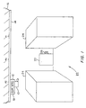
- Fig. 1 is a perspective view of a closed-circuit television surveillance system, using a rail mounted camera, in which the present invention may be applied.
- Fig. 2 is a block diagram of a surveillance system in accordance with the invention.
- Figs. 3A and 3B are respectively top and back isometric schematic diagrams used for explaining initialization and automatic target acquisition procedures carried out in accordance with the invention.
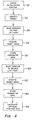
- Fig. 4 is a flow chart of an initialization routine carried out in accordance with the invention.
- Fig. 5 is a flow chart of a routine carried out in accordance with the invention for automatically acquiring a target in response to an alarm signal.
- Fig. 1 shows the interior of a building in which there is installed a surveillance system in accordance with the present invention.
- the system includes a surveillance camera 10 that is mounted on a carriage 12.
- the carriage 12 in turn, is movably supported on an elongated track or rail 14, which is suspended from the ceiling 16 of the building.
- the camera 10 may be of a conventional type which is subject to remote control as to the direction in which the camera is oriented.
- the camera is controllable for horizontal pivoting movement, known as “panning”, as well as vertical pivoting movement known as “tilting”.
- a motorized mirror assembly may be mounted on the carriage in association with the camera 10 for accomplishing tilting and panning adjustments of the direction of view of the camera.
- the carriage 12 includes a motor 18 which is also subject to remote control by the surveillance system.
- Appropriate encoding such as optical encoding (not shown) is provided along the rail 14 so that the position of the carriage 12 along the rail can be sensed and an appropriate carriage position signal provided to the control system.
- other techniques may be employed to determine the position of the carriage, such as detecting operation of motor 18.
- the carriage can be controllably moved to desired positions along the rail 14.
- connections for controlling the camera 10 and the carriage 12 can be via cable (in which case a cable reel carriage may be provided integrated with or separate from camera carriage 12) or by wireless communication links.
- an opaque cover or the like for hiding the camera 10 may be provided surrounding the rail 14 and the path of travel of the carriage 12.
- the building interior shown in Fig. 1 includes a door 20 located at the end of an aisle 22 formed between racks or tiers 24 of merchandise or the like.
- a sensor 26 is installed in proximity to the door 20 and provides an alarm signal when, for example, the door is opened.
- Fig. 2 illustrates the surveillance system of the present invention in block diagram form.
- CPU central processing unit
- microprocessor 30 Associated with the microprocessor 30 are a program memory 32, for storing control software, and a data memory 34 in which working data are stored, including, as will be seen, parameter data collected during an initialization routine.
- CPU 28 also includes an input/output (I/O) module 36 which is connected to microprocessor 30 and provides an interface between the CPU 28 and other portions of the surveillance system.
- I/O input/output
- I/O module 36 is connected by way of a signal path 37 to a pan motor 38, a tilt motor 40, a zoom motor 42 and a rail motor 44.
- Pan motor 38 provides the above-mentioned panning adjustments for the video camera 10
- tilt motor 40 provides the above-mentioned tilt adjustments of the video camera 10
- zoom motor 42 implements changes in the zoom condition of the camera 10
- rail or carriage motor 44 propels the carriage 12 along the rail 14.
- Each of these motors receives control signals from the CPU 28 by way of the I/O module 36 and the signal path 37, and all of these motors are carried on the carriage 12 (although, as an alternative, the carriage 12 may be driven by an off-board motor through a belt drive or the like).
- each of the motors 38, 40, 42, and 44 are arranged to provide position feedback signals indicative of the position of the motor or of the carriage, as the case may be. These signals are transmitted back to the CPU 28 by way of a signal path 46 and I/O module 36.
- the paths 37 and 46 may, for example, be embodied by appropriate caoling, or wireless data channels, etc.
- I/O module 36 Also connected to CPU 28 by way of I/O module 36 are a user terminal 48 and the above-mentioned sensor 26.
- the terminal 48 permits a human operator to input data to the CPU 28 in a conventional manner, and also permits the CPU 28 to display data to the human operator in a conventional manner.
- the I/O module 36 is provided with a communication channel from the sensor 26 for receiving therefrom the above-mentioned alarm signal, upon opening of the door 20 (Fig. 1).
- the surveillance system shown in Fig. 2 provides the customary capabilities for remote control of the camera 10 and carriage 12 by the human operator, including selective positioning of the carriage 12, and panning, tilting and zooming of the camera 10, all by way of signals input via the terminal 48.
- the surveillance system also includes a video display monitor 49 connected (or linked by wireless channel) to receive and display the video output signal provided by the camera 10.
- display 49 is shown as being separate from terminal 48, it is also contemplated to share a monitor portion of terminal 41 with display 49, by means of split screen, windowing, time sharing, superposition of a cursor and characters on the video display, and so forth.
- the rail 14, door 20 and merchandise tiers 24 are positioned with respect to each other so that the door 20 is within a line of sight of the camera 10 over a portion of the rail 12, but when the carriage 12 is positioned outside of that portion of the rail 14, the line of sight from the camera 10 to the door 20 is occluded by, for example, the tiers of merchandise 24.
- the door 20 is a target for which automatic image acquisition is desired. Accordingly, there will first be described an initialization procedure during which appropriate data is stored in the CPU 28 to allow for an automatic target acquisition operation in accordance with the invention.
- Fig. 3A and 3B are respectively top and back diagrammatic views which illustrate geometric relationships among a target (assumed to be door 20), the rail 14 (taken to be the "z-axis"), and various positions along rail 14 at which the carriage 12 may be located.
- the x-axis direction is taken to be the horizontal direction perpendicular to the rail 14, and the y-axis direction is taken to be the vertical direction.
- the horizontal plane which passes through the rail 14 will be referred to as the x-z plane, while the vertical plane which passes through rail 14 will be referred to as the y-z plane.
- Point R1 corresponds to a right-most position on the rail 14 from which there is a line of sight to the target door 20, and point R2 corresponds to the left-most position on the rail 14 from which there is a line of sight to the target door 20.
- a zero-reference or origin point is taken to be at a leftward position along the rail(z-axis), so that the position index of R1 is larger than the position index of R2.
- point Rn represents a position on the rail 14 that is closest to the target 20, and Rz indicates an arbitrary position between points R2 and R1 at which the carriage 12 and camera 10 may be located at any given time.
- the system is arranged so that the camera 12 may at some times be at positions along rail 14 that are outside of the range defined between point R2 and R1.
- the line B1 represents the projection on the x-z plane of the line of sight from point R1 to the target
- the line B2 represents the projection on the x-z plane of the line of sight from point R2 to the target.
- the dashed line Bz similarly represents the projection on the x-z plane of the line of sight from the arbitrary point Rz to the target
- the dotted line N represents the projection of the x-z plane of the line of sight from the point Rn to the target.
- the line segment A2 is defined between the points R2 and Rn, and the line segment A1 is defined between points Rn and R1.
- the line segment A12 is defined between the points Rn and Rz.
- the point Txz is located in the x-z plane directly above the target.
- the angle ⁇ 1 between line B1 and the z axis represents the required pan angle for the camera to acquire the target when the carriage is located at point R1
- the angle ⁇ 2 between the line B2 and the z axis represents the appropriate pan angle for the camera to acquire the target when the carriage is located at the point R2.
- the angle ⁇ z formed between the line Bz and the z axis represents the appropriate pan angle for acquiring the,target when the camera is located at point R z .
- Fig. 3B Reference to Fig. 3B will indicate that the appropriate camera tilt angles for target acquisition from points R2, Rz and R1 are schematically represented by the angles ⁇ 2, ⁇ z and ⁇ 1. It will also be noted from Fig. 3B that the line Dz represents the line of sight from point Rz to the target (not a projection), while the dotted line Y is the projection on the y-z plane of a normal line from the z axis to the target. Thus Y represents the vertical distance between the target and the x-z plane.
- the initialization procedure is commenced at step 50 by entry of an appropriate signal via user terminal 48 so that the microprocessor 30 begins to carry out an initialization routine.
- step 52 at which appropriate data entry is made to identify the target for purposes of future reference within the surveillance system.
- an appropriate prompt may be displayed on the terminal 48, and in response thereto the operator may enter a designation such as "target No. 1".
- target No. 1 the target object for which initialization data is about to be issued will thereafter be referred to within the surveillance system as "target No. 1” and a sensor or sensors associated with that target object will accordingly be recognized by the surveillance system as providing an alarm signal with respect to the identified target object.
- an alarm signal can be actuated with respect to a particular target by an appropriate operator input via the terminal 48. It will be understood that this arrangement permits the surveillance system to provide automatic acquisition for plural targets in response to respective alarm signals pertaining to the targets.
- step 54 at which the terminal 48 is operated so that the carriage is moved to the point at the end (for example at the right end) of a rang of positions along the rail 14 from which the target object may be acquired by the camera 10.
- that point will be identified as R1.
- step 56 is carried out, in which the operator causes the camera's direction of view to be adjusted, and perhaps also adjusts the zoom and focus condition of the camera, so that the target object (door 20) is imaged by the camera 10.
- the human operator When a satisfactory image of the target door 20 has been acquired through the camera 10, the human operator then enters a "select" signal or the like, in response to which the surveillance system stores in data memory 34 data which represents the current position (now assumed to be R1) of the carriage 12, as well as data indicating the pan and tilt angles of the direction of view of the camera 10 (step 58).
- step 60 at which the human operator moves the carriage 12 to the other end of the range from which there is a line of sight to the target door 20. In this case it is assumed that the other end is the left-most end of the viewable range, at point R2.
- the operator again causes the camera direction and zoom/focus conditions to be adjusted so that a satisfactory image of the target door 20 is obtained (step 62). Then, at step 64, again the "select" signal is entered via the terminal 48 so that the data representing the carriage position, as well as the camera direction (pan and tilt angles) is entered into the data memory 34.
- Step 66 follows, at which the position of point Rn is calculated on the basis of the data stored during steps 58 and 64.
- point Rn is assumed to be the optimum point for acquiring an image of the target 20, namely the closest position to the target along rail 14.
- Step 66 may be considered complete upon calculation of the position of the optimum viewpoint Rn.
- the calculated position of Rn together with the stored data indicative of the locations and the appropriate pan and tilt angles for the points R2 and R1, make it possible to calculate an appropriate camera direction (pan and tilt angles) as well as appropriate zoom and focus conditions for target acquisition from any carriage position between points R2 and R1.
- the zoom and focus conditions are a function of the distance from the carriage position to the target, and this quantity can be calculated based on the stored data.
- step 70 may include an automatically controlled procedure in which the carriage 12 is moved along rail 14 according to a predetermined pattern, while the direction, zoom, focus and so forth of the camera 10 are also adjusted in a predetermined pattern so that camera 10 performs routine surveillance by "walking a beat.”
- Step 72 the normal surveillance routine 70 continues until an alarm signal is received.
- Step 72 may be implemented by applying an interrupt to microprocessor 30 upon receipt of an alarm signal. Alternatively, for example, periodic polling may be carried out during normal surveillance to detect the presence of an alarm signal.
- step 74 If an alarm signal is received it is then determined whether the carriage 12 is located within range along the rail 14 from which there is a line of sight to the target (step 74). It will be assumed in the present case, initially, that an alarm signal has been generated by the sensor 26 associated with the door 20 ("target No. 1") and that the carriage 12 is at a point Rz (Figs. 3A and 3B) that is between points R1 and R2, and thus is within the range from which the target 20 can be acquired by the camera 10. In accordance with this assumption, step 76 follows step 74, and in step 76 the surveillance system (CPU 28) calculates an appropriate pan angle tilt angle, zoom condition and focus condition for the camera 10 so that an image of target 20 can be immediately provided on the video display 49.
- pan angle ⁇ z can be readily calculated from the initialization data and the current position Rz.
- Y may be calculated at step 66 of the initializatior routine (Fig. 4).
- the distance Dz from the point Rz to the target along the line of sight from point Rz for the target is calculated.
- the distance to the target from the current position of the camera 10 can be expressed in terms of the current position of the carriage 12 and other data that has previously been stored or calculated. Accordingly, at step 78, which follows step 76, the direction of view of the camera adjusted in accordance with the calculated pan and tilt angles and the appropriate zoom and focus conditions are applied so that the camera 10 provides an image of the target door 20. Then step 80 follows step 78, so that the carriage 12 is moved from the point Rz, at which the carriage was located when the alarm was received, to the optimum viewpoint Rn.
- pan angle, the tilt angle, the zoom condition and the focus condition are continuously updated, by calculations as described above, so that the camera continues to "track" the target; that is, the camera continuously provides an image of the target while the carriage is in motion from point Rz to point Rn.
- step 74 it is determined at step 74 that the carriage 12 is not within the range from which the target can be acquired, and step 82 therefore follows step 74.
- step 82 it is first determined whether the carriage 12 is closer to point R1 or point R2, and then the pan and tilt angles and the zoom and focus conditions for the camera are established in accordance with the previously stored parameters appropriate for that nearest point. Since, according to the present assumption, R1 is the nearest of the two points, the camera is adjusted to have a pan angle ⁇ 1 and a tilt angle ⁇ 1 . It will also be recognized that the appropriate camera focus and zoom conditions for the two limit points R1 and R2 can either be stored as part of the initialization procedure or can be calculated from other data obtained during initialization.
- step 84 at which the carriage 12 is moved toward the nearest limit point, in this case R1. Because the camera has already been adjusted so as to assume the appropriate pan and tilt, etc. for point R1, it will be understood that the target will be acquired immediately when the carriage reaches point R1.
- step 84 is a decision step 86, at which it is determined whether the nearest limit point has been reached. If not, the routine loops back to step 84. Otherwise, the routine proceeds to step 80, at which the carriage is moved from the limit point to optimum position Rn while providing continuous tracking of the target by the camera 10.
- steps 82 and 84 are presented as logically separate, those two steps can be overlapped in time so that the camera angle adjustment is carried out during movement of the carriage 12 toward the nearest point.
- steps 76 and 80 referred to calculations carried out to obtain pan, tilt, zoom and focus data for immediate target acquisition in response to an alarm (step 76) or during carriage movement (step 80) to update the pan and tilt angles and the zoom and focus conditions so that target acquisition was maintained during the carriage movement within the viewing range.
- pan, tilt, zoom and focus data are retrieved for target acquisition from a look up table that was formed during initialization.
- step 66 of the initialization procedure includes calculating, for each separately detectable carriage position in the target viewing range, appropriate pan, tilt, zoom and focus parameters for target acquisition. The resulting data is stored in a look up table for the target, and indexed in the table according to carriage position.
- the parameters stored in the look up table entries for the limit points are, of course, those obtained at steps 58 and 64. Then, during the target acquisition routine of Fig. 5, access is had to the look up table corresponding to the target to be acquired, and camera positioning and focus and zoom data are read out based on the current carriage position. If the current carriage position is outside of the viewing range for the target, the camera positioning data corresponding to the nearest position in the viewing range (i.e., the nearest limit point) is read out.
- the procedure described with respect to step 80 can be changed, or selectively changed, so that the carriage 12 is caused to reciprocate or "pace" back and forth between the points R1 and R2 in response to receipt of an alarm signal. While such "pacing" takes place, calculations as described above are carried out (or positioning data is retrieved from a look up table) so that the camera continuously tracks the target.
- the "pacing” may also be arranged to be performed over less than the entire range from which a line of sight exists. It is also contemplated that the carriage be moved, in response to an alarm, according to more complex patterns than simple pacing between two points in the viewing range.
- the system could be programmed during initialization so that, in response to an alarm, the carriage first paces a predetermined number of times between the optimum viewpoint and the right limit point, and then paces a predetermined number of times between the optimum viewpoint and the left limit point, and then paces again between the optimum viewpoint and the right limit point, and so forth.
- the carriage could be reciprocated several times over a narrow range around the optimum point, then over a wider range around the optimum point, and then over a still wider range.
- Other variations and permutations of such programmed responses to an alarm will readily occur to those who are skilled in the art.
- the above-described practice of the invention entails calculating the location of a closest point Rn to the target to provide an optimum viewpoint
- an alarm signal can be generated from a source other than a sensor.
- an alarm signal can be actuated by appropriate operator input via terminal 48 in a circumstance in which the operator wishes to obtain rapid and automatic acquisition of a particular target.
Landscapes
- Physics & Mathematics (AREA)
- General Physics & Mathematics (AREA)
- Engineering & Computer Science (AREA)
- Human Computer Interaction (AREA)
- Closed-Circuit Television Systems (AREA)
- Studio Devices (AREA)
Claims (28)
- Système de surveillance comprenant :une voie allongée positionnée le long d'un trajet,un moyen de chariot supporté sur ladite voie et mobile le long de celle-ci en vue de transporter une caméra de télévision (10) le long dudit trajet,un moyen de déplacement de chariot couplé audit moyen de chariot en vue de déplacer de façon sélective ledit moyen de chariot le long de ladite voie,un moyen associé à ladite caméra de télévision (10) et sensible à des signaux de commande de caméra en vue d'ajuster de façon sélective une direction d'observation et une condition de variation de focale de ladite caméra de télévision (10),un moyen de commande de chariot couplé audit moyen de déplacement de chariot et sensible aux signaux de commande de chariot en vue de positionner de façon sélective ledit moyen de chariot le long de ladite voie, etdes premier et second ensembles de paramètres d'initialisation etun moyen d'initialisation destiné à introduire à la fois des premier et second ensembles de paramètres d'initialisation, ledit premier ensemble de paramètres d'initialisation comprenant des premières données de position représentatives d'un premier point sélectionné le long de ladite voie allongée et des premières données de direction de caméra représentatives d'une première direction de caméra sélectionnée de sorte que ladite caméra de télévision (10) fournit une image d'un objet cible prédéterminé lorsque ledit moyen de chariot est positionné au niveau dudit premier point sélectionné, ledit second ensemble de paramètres d'initialisation comprenant des secondes données de position représentatives d'un second point sélectionné le long de ladite voie allongée et des secondes données de direction de caméra représentatives d'une seconde direction de caméra sélectionnée de sorte que ladite caméra de télévision fournit une image dudit objet cible prédéterminé lorsque ledit moyen de chariot est positionné au niveau dudit second point sélectionné.
- Système de surveillance selon la revendication 1, dans lequel chacun desdits ensembles de paramètres d'initialisation comprend des données de panoramique et d'inclinaison respectives.
- Système de surveillance selon la revendication 2, dans lequel ledit moyen d'initialisation comprend un moyen de sélection pouvant être mis en oeuvre par un opérateur humain en vue d'actionner une opération de mémorisation de paramètre et un moyen, sensible à une opération dudit moyen de sélection par ledit opérateur humain, en vue de détecter et de mémoriser des données de paramètres représentatives d'une position dudit moyen de chariot et d'une direction d'observation et d'une condition de variation de focale de ladite caméra de télévision (10) au moment où ledit moyen de sélection est mis en oeuvre.
- Système de surveillance selon la revendication 1, dans lequel lesdits premier et second points sélectionnés définissent entre ceux-ci une plage de positions le long dudit rail au niveau duquel ladite caméra (10) peut être orientée pour fournir une image dudit objet cible prédéterminé.
- Système de surveillance selon la revendication 4, comprenant en outre un moyen cible relié de façon fonctionnelle audit moyen de commande de chariot en vue de recevoir un signal d'acquisition cible et en vue de réponse au signal d'acquisition cible reçu en générant des signaux de commande de chariot de sorte que ledit moyen de commande de chariot déplace ledit moyen de chariot vers une position prédéterminée dans ladite plage de positions entre lesdits premier et second points sélectionnés.
- Système de surveillance selon la revendication 5, comprenant en outre un moyen relié de façon fonctionnelle audit moyen de commande de caméra en vue de répondre au signal de commande d'acquisition cible reçu en générant des signaux de commande de caméra sur la base desdits paramètres d'initialisation introduits afin d'ajuster la direction d'observation et une condition de variation de focale de ladite caméra de télévision (10) durant le déplacement dudit moyen de chariot dans ladite plage de positions de sorte que ladite caméra de télévision (10) fournit en permanence une image dudit objet cible prédéterminé durant un tel déplacement dudit moyen de chariot dans ladite plage de positions.
- Système de surveillance selon la revendication 6, comprenant en outre :un moyen destiné à calculer, sur la base desdits paramètres d'initialisation introduits, et pour chaque position parmi une pluralité de positions entre lesdits premier et second points sélectionnés, un angle de panoramique approprié, un angle d'inclinaison approprié, et une condition de variation de focale appropriée en vue de permettre à ladite caméra de télévision (10) de fournir une image dudit objet cible prédéterminé lorsque ledit moyen de chariot est positionné au niveau de la position respective parmi ladite pluralité de positions, etun moyen destiné à mémoriser des données représentatives des angles de panoramique et d'inclinaison calculés et des conditions de variation de focale dans une table de consultation indexée conformément à ladite pluralité de positions.
- Système de surveillance selon la revendication 5, comprenant en outre un moyen relié de façon fonctionnelle audit moyen de commande de caméra en vue de réponse au signal d'acquisition cible reçu en générant des signaux de commande de caméra conformément à des données sélectionnées parmi lesdites première et seconde données de direction de caméra, si ledit moyen de chariot n'est pas positionné à l'intérieur de ladite plage de positions au moment où ledit signal d'acquisition cible est reçu.
- Système de surveillance selon la revendication 8, dans lequel :si, audit moment où ledit signal d'acquisition cible est reçu, ledit moyen de chariot est positionné à l'extérieur de ladite plage de positions et plus proche dudit premier point sélectionné que dudit second point sélectionné, alors ledit moyen de commande de caméra amène la direction d'observation de ladite caméra de télévision à devenir ladite première direction de caméra sélectionnée en réponse audit signal d'acquisition cible reçu, etsi, audit moment où ledit signal d'acquisition cible est reçu, ledit moyen de chariot est positionné à l'extérieur de ladite plage de positions et plus proche dudit second point sélectionné que dudit premier point sélectionné, alors, ledit moyen de commande de caméra amène la direction d'observation de ladite caméra de télévision à devenir ladite seconde direction de caméra sélectionnée en réponse audit signal d'acquisition cible reçu.
- Système de surveillance selon la revendication 5, dans lequel ladite position prédéterminée se trouve à un point le plus proche dudit objet cible prédéterminé le long dudit rail, et comprenant en outre un moyen destiné à calculer sur la base desdits premier et second ensembles de paramètres d'initialisation, ledit point le plus proche et une direction optimum d'observation et une condition de variation de focale optimum en vue d'amener ladite caméra de télévision (10) à fournir une image dudit objet cible prédéterminé lorsque ledit moyen de chariot est positionné au niveau dudit point le plus proche.
- Système de surveillance selon la revendication 5, comprenant en outre un moyen de capteur destiné à fournir ledit signal d'acquisition cible audit moyen cible en réponse à une modification d'une condition physique au niveau dudit objet cible prédéterminé.
- Système de surveillance selon la revendication 4, comprenant en outre un moyen relié de façon fonctionnelle audit moyen de commande de chariot et audit moyen de commande de caméra en vue de recevoir un signal d'acquisition cible et en vue de répondre au signal d'acquisition cible reçu en générant des signaux de commande de chariot de sorte que ledit moyen de commande de chariot déplace ledit moyen de chariot pour le faire aller et venir entre deux points prédéterminés de ladite plage de positions définie par lesdits premier et second points sélectionnés et en vue de générer des signaux de commande de caméra durant un tel mouvement de va-et-vient dudit moyen de chariot afin d'ajuster la direction d'observation et la condition de variation de focale de ladite caméra de télévision (10) de sorte que ladite caméra de télévision (10) fournit en permanence une image dudit objet cible prédéterminé durant un tel mouvement de va-et-vient.
- Système de surveillance selon la revendication 12, dans lequel lesdits deux points prédéterminés entre lesquels ledit moyen de chariot se déplace en va-et-vient, sont lesdits premier et second points sélectionnés.
- Procédé d'initialisation d'un système de surveillance de télévision à circuit fermé fondé sur un rail, le système de surveillance comprenant une voie allongée positionnée le long d'un trajet, un moyen de chariot supporté sur ladite voie et mobile le long de celle-ci en vue de transporter une caméra de télévision (10) le long dudit trajet, un moyen de déplacement de chariot couplé audit moyen de chariot en vue de déplacer de façon sélective ledit moyen de chariot le long de ladite voie, un moyen de commande de caméra destiné à ajuster de façon sélective une direction d'observation et une condition de variation de focale de ladite caméra de télévision (10), et un moyen de commande de chariot destiné à positionner de façon sélective ledit moyen de chariot le long de ladite voie, le procédé comprenant les étapes consistant à :positionner ledit moyen de chariot au niveau d'un premier point sélectionné le long de ladite voie allongée,orienter la direction d'observation de ladite caméra de télévision (10) suivant une première observation de sorte que ladite caméra de télévision (10) fournit une image d'un objet cible prédéterminé au moment où ledit moyen de chariot se trouve audit premier point sélectionné,mémoriser un premier ensemble de paramètres d'initialisation qui comprend des premières données de position de voie représentatives dudit premier point sélectionné et des premières données de direction de caméra représentatives de ladite première orientation de la direction d'observation de ladite caméra de télévision (10),positionner ledit moyen de chariot au niveau d'un second point sélectionné le long de ladite voie,orienter la direction d'observation de ladite caméra de télévision (10) suivant une seconde orientation de sorte que ladite caméra de télévision (10) fournit une image dudit objet cible prédéterminé au moment où ledit moyen de chariot se trouve au niveau dudit second point sélectionné, etmémoriser un second ensemble de paramètres d'initialisation qui comprend des secondes données de position de voie représentatives dudit second point sélectionné et des secondes données de direction de caméra représentatives de ladite seconde orientation de la direction d'observation de ladite caméra de télévision (10).
- Procédé d'initialisation selon la revendication 14, dans lequel lesdites premières données de direction de caméra comprennent des premières données d'angle de panoramique et des premières données d'angle d'inclinaison et lesdites secondes données de direction de caméra comprennent des secondes données d'angle de panoramique et des secondes données d'angle d'inclinaison.
- Procédé d'initialisation selon la revendication 15, comprenant en outre l'étape consistant à calculer sur la base desdits premier et second ensembles de paramètres d'initialisation mémorisés, un point d'observation optimum le long de ladite voie qui est le plus proche dudit objet cible.
- Procédé d'initialisation selon la revendication 16, comprenant en outre l'étape consistant à calculer, sur la base desdits premier et second ensembles de paramètres mémorisés, un angle de panoramique optimum, un angle d'inclinaison optimum et une condition de variation de focale optimum en vue de permettre à ladite caméra de télévision (10) de fournir une image dudit objet cible prédéterminé lorsque ledit moyen de chariot est positionné au niveau dudit point d'observation optimum.
- Procédé d'initialisation selon la revendication 17, dans lequel ladite étape de calcul de ladite condition de variation de focale optimum comprend le calcul d'une distance entre ledit objet cible prédéterminé et ledit point d'observation optimum.
- Procédé d'initialisation selon la revendication 14, comprenant en outre les étapes consistant à :calculer sur la base desdits premier et second ensembles de paramètres d'initialisation mémorisés, et pour chaque position parmi une pluralité de positions entre lesdits premier et second points sélectionnés, un angle de panoramique approprié, un angle d'inclinaison approprié et une condition de variation de focale appropriée en vue de permettre à ladite caméra de télévision (10) de fournir une image dudit objet cible prédéterminé lorsque ledit moyen de chariot est positionné à la position respective parmi ladite pluralité de positions, etmémoriser des données représentatives des angles de panoramique et d'inclinaison calculés et des conditions de variation de focale dans une table de consultation indexée conformément à ladite pluralité de positions.
- Procédé selon la revendication 14, comprenant en outre les étapes consistant à :calculer à partir des données d'initialisation mémorisées un point d'observation optimum le long dudit trajet en vue d'acquérir une image dudit objet cible prédéterminé, et un angle de panoramique optimum, un angle d'inclinaison optimum et une condition de variation de focale optimum en vue d'acquérir ladite image dudit objet cible prédéterminé lorsque ladite caméra (10) se trouve au niveau dudit point d'observation optimum,recevoir un signal d'acquisition cible, etdéplacer ladite caméra (10) vers ledit point d'observation optimum en réponse audit signal d'acquisition cible reçu.
- Procédé selon la revendication 20, dans lequel ladite étape consistant à déplacer ladite caméra (10) vers ledit point d'observation optimum comprend le déplacement de ladite caméra (10) vers ledit point d'observation optimum le long d'une plage de positions entre lesdits deux points sélectionnés, et comprenant en outre l'étape consistant à ajuster la direction d'observation et la condition de variation de focale de ladite caméra (10) durant un tel déplacement de ladite caméra (10) le long de ladite plage de positions de sorte que ladite caméra (10) fournit en permanence une image dudit objet cible prédéterminé durant un tel déplacement de ladite caméra (10) dans ladite plage de positions.
- Procédé selon la revendication 21, dans lequel ladite étape d'initialisation comprend le calcul, sur la base desdites données d'initialisation mémorisées, et pour chaque position parmi une pluralité de positions entre lesdits deux points sélectionnés, d'un angle de panoramique approprié, d'un angle d'inclinaison approprié et d'une condition de variation de focale appropriée en vue de permettre à ladite caméra de télévision (10) de fournir une image dudit objet cible prédéterminé lorsque ladite caméra (10) est positionnée au niveau de la position respective parmi ladite pluralité de positions, et la mémorisation de données représentatives des angles de panoramique et d'inclinaison calculés et des conditions de variation de focale dans une table de consultation indexée conformément à ladite pluralité de positions.
- Procédé selon la revendication 20, dans lequel ledit point d'observation optimum se situe entre lesdits deux points sélectionnés et est plus proche dudit objet cible prédéterminé que tout autre point le long dudit trajet.
- Procédé selon la revendication 20, dans lequel ledit signal d'acquisition cible est reçu au moment où ladite caméra (10) ne se situe pas entre lesdits deux points sélectionnés sur ledit trajet, et ladite étape de déplacement comprend le déplacement de ladite caméra (10) vers un point plus proche parmi lesdits deux points sélectionnés, et comprenant en outre l'étape consistant à ajuster la direction d'observation de ladite caméra (10), au même moment la caméra (10) est déplacée vers ledit point plus proche parmi lesdits deux points sélectionnés, l'adite étape d'ajustement étant exécutée de sorte que la caméra (10) présente la même direction d'observation que celle qui est utilisée durant ladite étape d'initialisation afin d'attirer une image de l'objet cible prédéterminé à partir dudit point plus proche parmi lesdits deux points sélectionnés.
- Procédé selon la revendication 20, comprenant en outre l'étape consistant à déplacer ladite caméra (10) conformément à un motif prédéterminé en réponse audit signal d'acquisition cible reçu.
- Procédé selon la revendication 25, comprenant en outre l'étape consistant à ajuster en permanence la direction d'observation de ladite caméra (10) durant ledit déplacement de ladite caméra (10) conformément audit motif prédéterminé de sorte que ladite direction d'observation reste orientée vers ledit objet cible durant ledit déplacement de ladite caméra (10).
- Procédé selon la revendication 26, dans lequel ledit déplacement de ladite caméra (10) conformément audit motif prédéterminé comprend le déplacement en va-et-vient de ladite caméra (10) entre deux points prédéterminés.
- Procédé selon la revendication 27, dans lequel lesdits deux points prédéterminés entre lesquels ladite caméra (10) se déplace en va-et-vient sont lesdits deux points sélectionnés.
Applications Claiming Priority (2)
| Application Number | Priority Date | Filing Date | Title |
|---|---|---|---|
| US302341 | 1994-09-07 | ||
| US08/302,341 US5526041A (en) | 1994-09-07 | 1994-09-07 | Rail-based closed circuit T.V. surveillance system with automatic target acquisition |
Publications (3)
| Publication Number | Publication Date |
|---|---|
| EP0701232A2 EP0701232A2 (fr) | 1996-03-13 |
| EP0701232A3 EP0701232A3 (fr) | 1997-12-10 |
| EP0701232B1 true EP0701232B1 (fr) | 2002-04-17 |
Family
ID=23167346
Family Applications (1)
| Application Number | Title | Priority Date | Filing Date |
|---|---|---|---|
| EP95112903A Expired - Lifetime EP0701232B1 (fr) | 1994-09-07 | 1995-08-17 | Système de télévision à circuit fermé à caméra mobile et acquisition automatique de cible |
Country Status (6)
| Country | Link |
|---|---|
| US (1) | US5526041A (fr) |
| EP (1) | EP0701232B1 (fr) |
| JP (1) | JPH0888847A (fr) |
| BR (1) | BR9503950A (fr) |
| CA (1) | CA2149730C (fr) |
| DE (1) | DE69526397T2 (fr) |
Families Citing this family (95)
| Publication number | Priority date | Publication date | Assignee | Title |
|---|---|---|---|---|
| US8352400B2 (en) | 1991-12-23 | 2013-01-08 | Hoffberg Steven M | Adaptive pattern recognition based controller apparatus and method and human-factored interface therefore |
| US6628887B1 (en) | 1998-04-17 | 2003-09-30 | Honeywell International, Inc. | Video security system |
| EP0776573A4 (fr) * | 1994-07-26 | 1998-04-15 | Maxpro Systems Pty Ltd | Systeme de securite video |
| US5872594A (en) * | 1994-09-20 | 1999-02-16 | Thompson; Paul A. | Method for open loop camera control using a motion model to control camera movement |
| FR2725062B1 (fr) * | 1994-09-23 | 1997-04-04 | Douard Pierre Rene | Procede et dispositif de telesurveillance par cameras mobiles sur rails |
| CA2155719C (fr) * | 1994-11-22 | 2005-11-01 | Terry Laurence Glatt | Systeme de surveillance video avec cameras pilotes et asservies |
| JP3347510B2 (ja) * | 1995-03-13 | 2002-11-20 | キヤノン株式会社 | 画像入力装置 |
| US7895076B2 (en) | 1995-06-30 | 2011-02-22 | Sony Computer Entertainment Inc. | Advertisement insertion, profiling, impression, and feedback |
| US8574074B2 (en) | 2005-09-30 | 2013-11-05 | Sony Computer Entertainment America Llc | Advertising impression determination |
| AU1463797A (en) * | 1995-12-20 | 1997-07-14 | Mediamaxx Incorporated | Computer-controlled system for producing three-dimensional navigable photographs of areas and method thereof |
| US5844601A (en) * | 1996-03-25 | 1998-12-01 | Hartness Technologies, Llc | Video response system and method |
| US5953055A (en) * | 1996-08-08 | 1999-09-14 | Ncr Corporation | System and method for detecting and analyzing a queue |
| KR19990076722A (ko) * | 1996-10-24 | 1999-10-15 | 이데이 노부유끼 | 카메라 장치 |
| JP3943674B2 (ja) * | 1996-10-25 | 2007-07-11 | キヤノン株式会社 | カメラ制御システム並びにカメラサーバ及びその制御方法 |
| EP1455516A3 (fr) | 1996-10-31 | 2006-03-22 | Sensormatic Electronics Corporation | Système intelligent pour gérer des informations vidéo |
| DE19651172C2 (de) * | 1996-12-10 | 2003-08-28 | Dag Auerbach | Überwachungsanlage |
| US6727938B1 (en) * | 1997-04-14 | 2004-04-27 | Robert Bosch Gmbh | Security system with maskable motion detection and camera with an adjustable field of view |
| DE69805077T2 (de) * | 1997-07-30 | 2002-10-31 | Pinotage, Llc | Bildaufnahmevorrichtung |
| US6685366B1 (en) * | 1997-09-05 | 2004-02-03 | Robert Bosch Gmbh | Camera positioning system with optimized field of view |
| WO1999035850A1 (fr) * | 1997-12-31 | 1999-07-15 | Koninklijke Philips Electronics N.V. | Systeme de cameras multiples |
| US7755668B1 (en) | 1998-04-09 | 2010-07-13 | Johnston Gregory E | Mobile surveillance system |
| JPH11331822A (ja) * | 1998-05-15 | 1999-11-30 | Matsushita Electric Ind Co Ltd | 監視カメラ装置 |
| US6189838B1 (en) * | 1998-06-02 | 2001-02-20 | Sentry Technology, Corp. | Position detector for track mounted surveillance systems |
| JP2000083188A (ja) * | 1998-09-03 | 2000-03-21 | Matsushita Electric Ind Co Ltd | 監視カメラ装置 |
| US7966078B2 (en) | 1999-02-01 | 2011-06-21 | Steven Hoffberg | Network media appliance system and method |
| DE29903350U1 (de) * | 1999-02-24 | 1999-04-22 | Nordmann Kurt Dr | Überwachungsanlage |
| JP4243883B2 (ja) * | 1999-03-15 | 2009-03-25 | フジノン株式会社 | リモコン雲台システム |
| US6285297B1 (en) * | 1999-05-03 | 2001-09-04 | Jay H. Ball | Determining the availability of parking spaces |
| AU762221B2 (en) * | 1999-05-06 | 2003-06-19 | Lextar Technologies Limited | A surveillance system |
| AUPQ017199A0 (en) | 1999-05-06 | 1999-05-27 | Lextar Technologies Limited | A system for surveillance of an area |
| JP2001069496A (ja) * | 1999-08-31 | 2001-03-16 | Matsushita Electric Ind Co Ltd | 監視カメラ装置及び監視カメラの制御方法 |
| US7995096B1 (en) * | 1999-09-23 | 2011-08-09 | The Boeing Company | Visual security operations system |
| WO2007130681A2 (fr) | 2006-05-05 | 2007-11-15 | Sony Computer Entertainment America Inc. | Rotation des publicités |
| EP1107584B1 (fr) * | 1999-12-03 | 2008-08-27 | Fujinon Corporation | Dispositif de poursuite automatique |
| WO2001075743A1 (fr) * | 2000-04-03 | 2001-10-11 | The Pugliese Company | Systeme et procede d'affichage et de vente de marchandises et de services |
| US7151562B1 (en) * | 2000-08-03 | 2006-12-19 | Koninklijke Philips Electronics N.V. | Method and apparatus for external calibration of a camera via a graphical user interface |
| US8751310B2 (en) | 2005-09-30 | 2014-06-10 | Sony Computer Entertainment America Llc | Monitoring advertisement impressions |
| US6995788B2 (en) * | 2001-10-10 | 2006-02-07 | Sony Computer Entertainment America Inc. | System and method for camera navigation |
| JP3754320B2 (ja) * | 2001-05-18 | 2006-03-08 | 三洋電機株式会社 | 画像信号処理装置 |
| US20050064926A1 (en) * | 2001-06-21 | 2005-03-24 | Walker Jay S. | Methods and systems for replaying a player's experience in a casino environment |
| US20020196342A1 (en) * | 2001-06-21 | 2002-12-26 | Walker Jay S. | Methods and systems for documenting a player's experience in a casino environment |
| IL150123A0 (en) * | 2002-06-10 | 2003-07-06 | Shahar Avneri | Security system |
| US20050134685A1 (en) * | 2003-12-22 | 2005-06-23 | Objectvideo, Inc. | Master-slave automated video-based surveillance system |
| US7528881B2 (en) * | 2003-05-02 | 2009-05-05 | Grandeye, Ltd. | Multiple object processing in wide-angle video camera |
| US20100002070A1 (en) | 2004-04-30 | 2010-01-07 | Grandeye Ltd. | Method and System of Simultaneously Displaying Multiple Views for Video Surveillance |
| US20080274798A1 (en) * | 2003-09-22 | 2008-11-06 | Walker Digital Management, Llc | Methods and systems for replaying a player's experience in a casino environment |
| US20050104958A1 (en) * | 2003-11-13 | 2005-05-19 | Geoffrey Egnal | Active camera video-based surveillance systems and methods |
| US7051938B2 (en) * | 2003-12-29 | 2006-05-30 | Motorola, Inc. | System and method for a multi-directional imaging system |
| DE102004018410A1 (de) * | 2004-04-16 | 2005-11-03 | Robert Bosch Gmbh | Sicherheitssystem und Verfahren zu dessen Betrieb |
| US8427538B2 (en) * | 2004-04-30 | 2013-04-23 | Oncam Grandeye | Multiple view and multiple object processing in wide-angle video camera |
| FR2870075B1 (fr) * | 2004-05-05 | 2006-08-04 | Hymatom Sa | Systeme de videosurveillance a cameras fixes et a camera mobile en rotation et en translation |
| US7623156B2 (en) * | 2004-07-16 | 2009-11-24 | Polycom, Inc. | Natural pan tilt zoom camera motion to preset camera positions |
| US8763157B2 (en) * | 2004-08-23 | 2014-06-24 | Sony Computer Entertainment America Llc | Statutory license restricted digital media playback on portable devices |
| DE102004043816B4 (de) * | 2004-09-08 | 2006-08-31 | Paulussen Systems Gmbh | Videoüberwachungssystem und Verfahren zu dessen Betrieb |
| US20060071933A1 (en) | 2004-10-06 | 2006-04-06 | Sony Computer Entertainment Inc. | Application binary interface for multi-pass shaders |
| US7189909B2 (en) * | 2004-11-23 | 2007-03-13 | Román Viñoly | Camera assembly for finger board instruments |
| EP1897075B1 (fr) * | 2005-06-20 | 2013-01-02 | Rotatech Pty Ltd. | Appareil directionnel de prise de vues de surveillance avec un anneau de détecteurs directionnels |
| US7636126B2 (en) | 2005-06-22 | 2009-12-22 | Sony Computer Entertainment Inc. | Delay matching in audio/video systems |
| ATE477565T1 (de) * | 2005-06-30 | 2010-08-15 | Planum Vision Ltd | Überwachungssystem und -verfahren zum detektieren einer verbotenen bewegung auf einem vorbestimmten weg |
| US8577411B2 (en) * | 2005-07-01 | 2013-11-05 | Access Co., Ltd. | Broadcast program scene report system and method, mobile terminal device, and computer program |
| US9363487B2 (en) * | 2005-09-08 | 2016-06-07 | Avigilon Fortress Corporation | Scanning camera-based video surveillance system |
| US20070058717A1 (en) * | 2005-09-09 | 2007-03-15 | Objectvideo, Inc. | Enhanced processing for scanning video |
| US8626584B2 (en) | 2005-09-30 | 2014-01-07 | Sony Computer Entertainment America Llc | Population of an advertisement reference list |
| US8676900B2 (en) | 2005-10-25 | 2014-03-18 | Sony Computer Entertainment America Llc | Asynchronous advertising placement based on metadata |
| US11004089B2 (en) | 2005-10-25 | 2021-05-11 | Sony Interactive Entertainment LLC | Associating media content files with advertisements |
| US10657538B2 (en) | 2005-10-25 | 2020-05-19 | Sony Interactive Entertainment LLC | Resolution of advertising rules |
| US20070118425A1 (en) | 2005-10-25 | 2007-05-24 | Podbridge, Inc. | User device agent for asynchronous advertising in time and space shifted media network |
| US7993196B2 (en) * | 2006-01-20 | 2011-08-09 | Wms Gaming Inc. | Wagering game with symbol strings dictating winning outcomes |
| US7965859B2 (en) | 2006-05-04 | 2011-06-21 | Sony Computer Entertainment Inc. | Lighting control of a user environment via a display device |
| US7880746B2 (en) | 2006-05-04 | 2011-02-01 | Sony Computer Entertainment Inc. | Bandwidth management through lighting control of a user environment via a display device |
| US8416247B2 (en) | 2007-10-09 | 2013-04-09 | Sony Computer Entertaiment America Inc. | Increasing the number of advertising impressions in an interactive environment |
| US8769558B2 (en) | 2008-02-12 | 2014-07-01 | Sony Computer Entertainment America Llc | Discovery and analytics for episodic downloaded media |
| GB2458661A (en) * | 2008-03-26 | 2009-09-30 | Sasan Yadrandji Aghdam | Remote-controlled rail-mounted IP camera |
| JP5072733B2 (ja) * | 2008-06-25 | 2012-11-14 | キヤノン株式会社 | 撮像装置及び撮像装置の制御方法 |
| US8763090B2 (en) | 2009-08-11 | 2014-06-24 | Sony Computer Entertainment America Llc | Management of ancillary content delivery and presentation |
| US10786736B2 (en) | 2010-05-11 | 2020-09-29 | Sony Interactive Entertainment LLC | Placement of user information in a game space |
| JP2012069022A (ja) * | 2010-09-27 | 2012-04-05 | Hitachi Ltd | 監視システム |
| US8791911B2 (en) | 2011-02-09 | 2014-07-29 | Robotzone, Llc | Multichannel controller |
| DE102011014552A1 (de) * | 2011-03-21 | 2012-09-27 | Rwe Deutschland Ag | Baustellencontainer sowie Verfahren zur Baustellenfernüberwachung unter Verwendung wenigstens eines Baustellencontainers |
| ITMI20110473A1 (it) * | 2011-03-25 | 2012-09-26 | Special Projects Snc Di Ferdinando Garetti E Franc | Macchina per la movimentazione di telecamere professionali ad alta velocita' con movimento di rotazione sull'asse dell'ottica,avanzamento lineare con sistema di messa a fuoco automatizzato. |
| US9390617B2 (en) * | 2011-06-10 | 2016-07-12 | Robotzone, Llc | Camera motion control system with variable autonomy |
| US9342817B2 (en) | 2011-07-07 | 2016-05-17 | Sony Interactive Entertainment LLC | Auto-creating groups for sharing photos |
| US9286516B2 (en) | 2011-10-20 | 2016-03-15 | Xerox Corporation | Method and systems of classifying a vehicle using motion vectors |
| US8971581B2 (en) | 2013-03-15 | 2015-03-03 | Xerox Corporation | Methods and system for automated in-field hierarchical training of a vehicle detection system |
| US9171213B2 (en) | 2013-03-15 | 2015-10-27 | Xerox Corporation | Two-dimensional and three-dimensional sliding window-based methods and systems for detecting vehicles |
| US9726463B2 (en) | 2014-07-16 | 2017-08-08 | Robtozone, LLC | Multichannel controller for target shooting range |
| US12149832B2 (en) * | 2015-04-14 | 2024-11-19 | ETAK Systems, LLC | 360 degree camera apparatus and monitoring system |
| JP6658277B2 (ja) * | 2016-04-28 | 2020-03-04 | 中国電力株式会社 | 障害物確認装置及び障害物確認方法 |
| US10846779B2 (en) | 2016-11-23 | 2020-11-24 | Sony Interactive Entertainment LLC | Custom product categorization of digital media content |
| US10860987B2 (en) | 2016-12-19 | 2020-12-08 | Sony Interactive Entertainment LLC | Personalized calendar for digital media content-related events |
| US10931991B2 (en) | 2018-01-04 | 2021-02-23 | Sony Interactive Entertainment LLC | Methods and systems for selectively skipping through media content |
| JP7235853B2 (ja) | 2018-08-30 | 2023-03-08 | キヤノンバージニア, インコーポレイテッド | 自律型監視システム |
| WO2020185935A1 (fr) | 2019-03-14 | 2020-09-17 | Canon Virginia, Inc. | Système de chariot |
| CN112750062A (zh) * | 2019-10-31 | 2021-05-04 | 比亚迪股份有限公司 | 车站的乘客服务控制方法、系统和终端设备 |
| CN116311730B (zh) * | 2022-12-23 | 2024-05-03 | 北京广监云科技有限公司 | 一种通过视频分析对危险区域违规进入的专用系统设备 |
Family Cites Families (14)
| Publication number | Priority date | Publication date | Assignee | Title |
|---|---|---|---|---|
| US4644845A (en) * | 1972-05-18 | 1987-02-24 | Garehime Jacob W Jr | Surveillance and weapon system |
| US3935380A (en) * | 1974-12-06 | 1976-01-27 | Coutta John M | Surveillance system |
| US4027329A (en) * | 1974-12-06 | 1977-05-31 | Coutta John M | Surveillance system |
| US4337482A (en) * | 1979-10-17 | 1982-06-29 | Coutta John M | Surveillance system |
| US4326218A (en) * | 1980-11-14 | 1982-04-20 | Coutta John M | Surveillance system |
| US4510526A (en) * | 1983-04-19 | 1985-04-09 | Coutta John M | Surveillance system |
| FR2633134A1 (fr) * | 1988-06-15 | 1989-12-22 | Boucher Bernard | Installation de surveillance video |
| DE3902076C1 (fr) * | 1989-01-25 | 1990-08-23 | Messerschmitt-Boelkow-Blohm Gmbh, 8012 Ottobrunn, De | |
| US5109278A (en) * | 1990-07-06 | 1992-04-28 | Commonwealth Edison Company | Auto freeze frame display for intrusion monitoring system |
| KR930010843B1 (ko) * | 1990-12-15 | 1993-11-12 | 삼성전자 주식회사 | 이동감시 카메라장치 |
| US5241380A (en) * | 1991-05-31 | 1993-08-31 | Video Sentry Corporation | Track mounted surveillance system having multiple use conductors |
| US5225863A (en) * | 1991-08-15 | 1993-07-06 | Weir Jones Iain | Remotely operated camera system with battery recharging system |
| JPH07104835A (ja) * | 1993-10-07 | 1995-04-21 | Hitachi Ltd | 移動式点検ロボットシステムの制御,解析,操作装置 |
| JP3084647B2 (ja) * | 1993-12-27 | 2000-09-04 | 株式会社日立製作所 | 図面管理装置 |
-
1994
- 1994-09-07 US US08/302,341 patent/US5526041A/en not_active Expired - Lifetime
-
1995
- 1995-05-18 CA CA002149730A patent/CA2149730C/fr not_active Expired - Lifetime
- 1995-08-17 DE DE69526397T patent/DE69526397T2/de not_active Expired - Lifetime
- 1995-08-17 EP EP95112903A patent/EP0701232B1/fr not_active Expired - Lifetime
- 1995-09-06 BR BR9503950A patent/BR9503950A/pt not_active IP Right Cessation
- 1995-09-07 JP JP7254518A patent/JPH0888847A/ja active Pending
Also Published As
| Publication number | Publication date |
|---|---|
| CA2149730A1 (fr) | 1996-03-08 |
| DE69526397D1 (de) | 2002-05-23 |
| JPH0888847A (ja) | 1996-04-02 |
| DE69526397T2 (de) | 2002-11-28 |
| CA2149730C (fr) | 2005-10-04 |
| EP0701232A3 (fr) | 1997-12-10 |
| BR9503950A (pt) | 1996-09-24 |
| EP0701232A2 (fr) | 1996-03-13 |
| US5526041A (en) | 1996-06-11 |
Similar Documents
| Publication | Publication Date | Title |
|---|---|---|
| EP0701232B1 (fr) | Système de télévision à circuit fermé à caméra mobile et acquisition automatique de cible | |
| KR100660762B1 (ko) | 카메라 핸드오프 시스템 및 카메라 선택 방법 | |
| US5745166A (en) | Video security system field of the invention | |
| US6215519B1 (en) | Combined wide angle and narrow angle imaging system and method for surveillance and monitoring | |
| EP0907940B1 (fr) | Systeme de securite a detecteur de mouvement masquable et camera a champ de vision reglable | |
| US5980123A (en) | System and method for detecting an intruder | |
| US6628887B1 (en) | Video security system | |
| US20050071046A1 (en) | Surveillance system and surveillance robot | |
| US20030103138A1 (en) | Video security and control system | |
| JP2006523043A (ja) | 監視を行なう方法及びシステム | |
| RU83675U1 (ru) | Система видеомониторинга | |
| JP2003158664A (ja) | カメラ制御装置 | |
| JPH09322053A (ja) | 自動撮影カメラシステムにおける被写体の撮影方法。 | |
| JP2008117132A (ja) | 防犯ロボットシステム及び防犯ロボットによる監視方法、警告方法 | |
| JP6725041B2 (ja) | 追跡システム、追跡方法および追跡プログラム | |
| JPH11275566A (ja) | 監視カメラ装置 | |
| JPH11142958A (ja) | 自動情報処理装置の内蔵カメラの自動姿勢制御方法および自動姿勢制御システム | |
| JP3549332B2 (ja) | 自動撮影カメラシステム | |
| JPH1066057A (ja) | 遠隔監視装置 | |
| JPH0981868A (ja) | 侵入体監視装置 | |
| JP2003163929A (ja) | 映像監視装置 | |
| KR100198143B1 (ko) | 감시장치 | |
| JP3336626B2 (ja) | 監視装置 | |
| JP2007172509A (ja) | 顔検出照合装置 | |
| CA2390265C (fr) | Systeme de securite et de controle video |
Legal Events
| Date | Code | Title | Description |
|---|---|---|---|
| PUAI | Public reference made under article 153(3) epc to a published international application that has entered the european phase |
Free format text: ORIGINAL CODE: 0009012 |
|
| AK | Designated contracting states |
Kind code of ref document: A2 Designated state(s): DE FR GB SE |
|
| PUAL | Search report despatched |
Free format text: ORIGINAL CODE: 0009013 |
|
| AK | Designated contracting states |
Kind code of ref document: A3 Designated state(s): DE FR GB SE |
|
| 17P | Request for examination filed |
Effective date: 19980528 |
|
| 17Q | First examination report despatched |
Effective date: 20000620 |
|
| GRAG | Despatch of communication of intention to grant |
Free format text: ORIGINAL CODE: EPIDOS AGRA |
|
| GRAG | Despatch of communication of intention to grant |
Free format text: ORIGINAL CODE: EPIDOS AGRA |
|
| GRAH | Despatch of communication of intention to grant a patent |
Free format text: ORIGINAL CODE: EPIDOS IGRA |
|
| RAP1 | Party data changed (applicant data changed or rights of an application transferred) |
Owner name: SENSORMATIC ELECTRONICS CORPORATION |
|
| REG | Reference to a national code |
Ref country code: GB Ref legal event code: IF02 |
|
| GRAH | Despatch of communication of intention to grant a patent |
Free format text: ORIGINAL CODE: EPIDOS IGRA |
|
| GRAA | (expected) grant |
Free format text: ORIGINAL CODE: 0009210 |
|
| AK | Designated contracting states |
Kind code of ref document: B1 Designated state(s): DE FR GB SE |
|
| REF | Corresponds to: |
Ref document number: 69526397 Country of ref document: DE Date of ref document: 20020523 |
|
| ET | Fr: translation filed | ||
| PLBE | No opposition filed within time limit |
Free format text: ORIGINAL CODE: 0009261 |
|
| STAA | Information on the status of an ep patent application or granted ep patent |
Free format text: STATUS: NO OPPOSITION FILED WITHIN TIME LIMIT |
|
| 26N | No opposition filed |
Effective date: 20030120 |
|
| PGFP | Annual fee paid to national office [announced via postgrant information from national office to epo] |
Ref country code: SE Payment date: 20030821 Year of fee payment: 9 |
|
| REG | Reference to a national code |
Ref country code: FR Ref legal event code: CA |
|
| PG25 | Lapsed in a contracting state [announced via postgrant information from national office to epo] |
Ref country code: SE Free format text: LAPSE BECAUSE OF NON-PAYMENT OF DUE FEES Effective date: 20040818 |
|
| REG | Reference to a national code |
Ref country code: GB Ref legal event code: 732E |
|
| EUG | Se: european patent has lapsed | ||
| REG | Reference to a national code |
Ref country code: GB Ref legal event code: 732E Free format text: REGISTERED BETWEEN 20101111 AND 20101117 |
|
| REG | Reference to a national code |
Ref country code: FR Ref legal event code: TP Owner name: SENSORMATIC ELECTRONICS, LLC, US Effective date: 20110913 |
|
| REG | Reference to a national code |
Ref country code: DE Ref legal event code: R082 Ref document number: 69526397 Country of ref document: DE Representative=s name: HAFNER & PARTNER, DE |
|
| REG | Reference to a national code |
Ref country code: DE Ref legal event code: R082 Ref document number: 69526397 Country of ref document: DE Representative=s name: HAFNER & PARTNER, DE Effective date: 20130612 Ref country code: DE Ref legal event code: R081 Ref document number: 69526397 Country of ref document: DE Owner name: TYCO FIRE & SECURITY GMBH, CH Free format text: FORMER OWNER: SENSORMATIC ELECTRONICS, LLC, BOCA RATON, FLA., US Effective date: 20130612 Ref country code: DE Ref legal event code: R081 Ref document number: 69526397 Country of ref document: DE Owner name: TYCO FIRE & SECURITY GMBH, CH Free format text: FORMER OWNER: SENSORMATIC ELECTRONICS, LLC, BOCA RATON, US Effective date: 20130612 |
|
| PGFP | Annual fee paid to national office [announced via postgrant information from national office to epo] |
Ref country code: DE Payment date: 20140827 Year of fee payment: 20 |
|
| PGFP | Annual fee paid to national office [announced via postgrant information from national office to epo] |
Ref country code: GB Payment date: 20140827 Year of fee payment: 20 Ref country code: FR Payment date: 20140818 Year of fee payment: 20 |
|
| REG | Reference to a national code |
Ref country code: DE Ref legal event code: R071 Ref document number: 69526397 Country of ref document: DE |
|
| REG | Reference to a national code |
Ref country code: GB Ref legal event code: PE20 Expiry date: 20150816 |
|
| PG25 | Lapsed in a contracting state [announced via postgrant information from national office to epo] |
Ref country code: GB Free format text: LAPSE BECAUSE OF EXPIRATION OF PROTECTION Effective date: 20150816 |