EP0701302A1 - Système de verrouillage pour un connecteur électrique - Google Patents
Système de verrouillage pour un connecteur électriqueInfo
- Publication number
- EP0701302A1 EP0701302A1 EP95306009A EP95306009A EP0701302A1 EP 0701302 A1 EP0701302 A1 EP 0701302A1 EP 95306009 A EP95306009 A EP 95306009A EP 95306009 A EP95306009 A EP 95306009A EP 0701302 A1 EP0701302 A1 EP 0701302A1
- Authority
- EP
- European Patent Office
- Prior art keywords
- electrical connector
- initiator
- locking system
- connector
- tapered
- Prior art date
- Legal status (The legal status is an assumption and is not a legal conclusion. Google has not performed a legal analysis and makes no representation as to the accuracy of the status listed.)
- Withdrawn
Links
- 239000003999 initiator Substances 0.000 claims abstract description 49
- 238000003780 insertion Methods 0.000 claims abstract description 33
- 230000037431 insertion Effects 0.000 claims abstract description 33
- 238000000605 extraction Methods 0.000 claims abstract description 18
- 230000000295 complement effect Effects 0.000 claims abstract description 6
- 230000008878 coupling Effects 0.000 claims description 6
- 238000010168 coupling process Methods 0.000 claims description 6
- 238000005859 coupling reaction Methods 0.000 claims description 6
- 230000014759 maintenance of location Effects 0.000 description 5
- 238000005259 measurement Methods 0.000 description 3
- 238000010276 construction Methods 0.000 description 2
- 238000013461 design Methods 0.000 description 2
- 239000002184 metal Substances 0.000 description 2
- 238000013459 approach Methods 0.000 description 1
- 230000001010 compromised effect Effects 0.000 description 1
- 230000013011 mating Effects 0.000 description 1
- 238000012360 testing method Methods 0.000 description 1
Images

Classifications
-
- H—ELECTRICITY
- H01—ELECTRIC ELEMENTS
- H01R—ELECTRICALLY-CONDUCTIVE CONNECTIONS; STRUCTURAL ASSOCIATIONS OF A PLURALITY OF MUTUALLY-INSULATED ELECTRICAL CONNECTING ELEMENTS; COUPLING DEVICES; CURRENT COLLECTORS
- H01R13/00—Details of coupling devices of the kinds covered by groups H01R12/70 or H01R24/00 - H01R33/00
- H01R13/62—Means for facilitating engagement or disengagement of coupling parts or for holding them in engagement
- H01R13/627—Snap or like fastening
- H01R13/6271—Latching means integral with the housing
- H01R13/6273—Latching means integral with the housing comprising two latching arms
Definitions
- This invention relates to an electrical connector for coupling an initiator of an airbag assembly to an electrical connector that is connected to the sensor circuitry of a vehicle, and more particularly to a locking system for such a connector requiring a lesser force for connecting and a substantially greater force for disconnecting the initiator and the electrical connector.
- an airbag is inflated by receiving gas from an airbag inflator actuated by an initiator.
- the initiator has electrical terminals which are in contact with and receive electrical signals from vehicle circuitry generating an electrical signal when the vehicle decelerates above a predetermined rate.
- the electrical signal actuates the initiator and thereby the inflator which provides the gas for deploying the airbag.
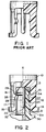
- a common prior art approach is to utilize arcuate ribs on the base of the initiator which mate with arcuate grooves in the body of a female connector on which the initiator base is mounted.
- Such structure is illustrated in Fig. 1 of this Application and is used in the electrical connector system shown and described in U.S. Patent 5,178,547.
- Such prior art electrical connector structure is shown in more detail in Figs. 3 to 6 of said U.S. Patent 5,178,547.
- One problem with such structure is the low retention value of the arrangement which generally will require less force to disconnect the connector than is required to engage the connector.
- Still another object of the present invention is to provide a new and improved electrical connector locking system for coupling an initiator of an airbag assembly to an electrical connector which requires an insertion force which is substantially less than the force required for disengaging the connector from the initiator.
- an electrical connector locking system for coupling an initiator of an airbag assembly to an electrical connector that is connected to sensor circuitry of a vehicle containing the airbag assembly.
- An initiator base having a pair of legs extending therefrom and having a plurality of male electrical terminals extending therethrough and being positioned between said legs, is provided with each of the legs having a radially inwardly protruding element having tapered surfaces forming a ramp on each of the legs.
- An electrical connector having a plurality of female electrical terminals housed therein is adapted to mate with the male electrical terminals extending from the initiator base.
- Radially inwardly extending notches positioned in the electrical connector are adapted to essentially complementarily mesh with and engage the protruding elements of the legs of the initiator base for thereby locking the connector on the initiator base.
- Figure 1 is a partial cross-sectional, elevational view of an initiator base illustrating the arcuate rib electrical connector engagement structure employed in the prior art.
- Figure 2 is a partial cross-sectional, elevational view of the electrical connector locking system in accordance with the present invention, with part of the electrical connector portion omitted for purposes of better illustrating the invention.
- Figure 3 is a partial cross-sectional, elevational view of the initiator base portion of the connector locking system as shown in Fig. 2 .
- Figure 4 is a partial cross-sectional, elevational view of the electrical connector portion of the connector locking system illustrated in Fig. 2 .
- the present invention is directed to an electrical connector locking system for coupling an initiator of an airbag assembly to an electrical connector that is connected to sensor circuitry of a vehicle containing an airbag assembly.
- the particular type of initiator, airbag assembly and sensor circuitry of a vehicle in which the airbag assembly is mounted are known in the art and, accordingly, are not described in detail as they do not in themselves constitute features of the present invention. Only the electrical connector locking system in which the invention resides will be described in detail.
- a generally circular initiator base 10 having conventional initiator structure mounted thereon has a pair of radially opposed legs 12 and 16 extending axially downwardly therefrom in the same direction, with each leg terminating at its distal end in a radially outwardly extending foot 14 and 18 , respectively.
- a plurality of male electrical terminals 20 extend axially downwardly from the base 10 between the radially opposed legs 12 and 16 (also see Fig. 3 ).
- Leg 12 on its radially inward surface 13 , has a radially inwardly protruding element 22 having two tapered surfaces 24 and 25 , said two tapered surfaces being tapered radially inwardly and converging together thereby forming a ramp on leg 12 .
- leg 16 also has, on its radially inward surface 17 , a radially inwardly protruding element 26 thereon having two tapered surfaces 28 and 29 , said two tapered surfaces also being tapered radially inward and converging toward each other and thereby forming a ramp on leg 16 .
- radially inwardly protruding ramp elements 22 and 26 are diametrically opposed to each other and positioned on radially opposite sides of the male electrical terminals 20 .
- An electrical connector element indicated generally by reference numeral 30 comprises a base end 30a and an insertion end 30b joined by an intermediate projecting portion 31 adapted to be received by the initiator base 10 .
- the electrical connector element 30 has a plurality of, generally two, female electrical terminals in the form of metal sleeves 32 housed in the projecting portion 31 thereof and open at the insertion end 30b of the connector element.
- the metal sleeves 32 are adapted to mate with and receive the male electrical terminals 20 extending from the initiator base 10 . Accordingly, when the connector element 30 is inserted or plugged into the initiator base 10 , electrical contact is made between the male terminals 20 and the female electrical terminals 32 which are connected to the sensor circuitry of the vehicle containing the airbag assembly.
- the projecting portion 31 of electrical connector 30 is provided with radially inwardly extending notches 34 and 37 (see also Fig. 4 ) which are adapted to mesh with and engage the protruding ramp elements 22 and 26 , respectively, of the initiator base 10 for locking the connector 30 on the initiator base 10 as is partially shown in Fig. 2 .
- Notches 34 and 37 of electrical connector element 30 are formed on the radially outward surface 31a of projecting portion 31 of the electrical connector to be complementary to protruding elements 22 and 26 of the inflator base 10 .
- Notch 34 is formed by two converging tapered surfaces 33 and 35 , said two tapered surfaces being tapered radially inwardly from outer surface 31a and converging to form notch 34 which is complementary in shape to protruding element 22 .
- notch 37 is formed by two converging tapered surfaces 38 and 39 , said two tapered surfaces being tapered radially inwardly from outer surface 31a and converging to form notch 37 which is complementary in shape to protruding element 26 . It will be appreciated that although the two notches 34 and 37 are described as separate notches on outer surface 31a , said notches may, if desired, be two portions of a continuous circular notch around connector 30 .
- connector surface 31a tapers radially inwardly from notches 34 and 37 to insertion end 30b of the connector to provide radially inwardly tapered insertion surfaces 36a and 36b .
- insertion surfaces 36a and 36b are described as separate surfaces on outer surface 31a , said insertion surfaces may, if desired, be two portions of a continuous circular insertion surface around connector 30 , especially when the two notches 34 and 37 are two portions of a continuous circular notch.
- the purpose of the mating and interlocking protruding elements 22 and 26 and their complementary notches 34 and 37 is to lock the connector 30 in position on the initiator base 10 .
- the ultimate purpose is to physically maintain electrical connection between the initiator and the vehicle circuitry so as not to compromise the operation of the airbag system.
- the requirements are for providing a larger force for extracting the connector 30 and female terminals 32 from the male electrical terminals 20 than is required to insert the connector 30 and female terminals on the male electrical terminals 20 in the initiator base 10 .
- the insertion and extraction values can be customized to meet the specification of a particular locking system and ensure that the extraction force is significantly greater than the insertion force.
- the insertion force is generally controlled primarily by the angle A of tapered surfaces 24 and 28 of ramp elements 22 and 26 and the angle C of tapered insertion surfaces 36a and 36b of connector 30 .
- the extraction force is generally controlled by the angle B of tapered extraction surfaces 25 and 29 of ramp elements 22 and 26 and the generally equivalent angle D of tapered extraction surface 35 and 39 of notches 34 and 37 , respectively.
- Insertion surface angles A and C will generally be within the range of from about 15° to about 25°, preferably from about 20° to about 22°.
- Extraction surface angles B and D will generally be in the range of from about 30° to about 80°, preferably from about 40° to about 75°, and most preferably is about 42°to about 44°.
- the locking arrangements of this invention for which data is provided in Table II had insertion angles A and C of 20° to 22° and extraction angles B and D of 42° to 44°.
- the insertion force required on the present invention is more than twice that required by the prior art type construction while the extraction value is increased more than three times of that of the prior art construction thereby solving the longstanding problem of low retention values for the connection structure. It is noted that in the present invention the extraction force is at least 50% greater than that of the insertion force. Note that the prior art provides less extraction force than the insertion force which is an undesirable feature because mechanical problems such as vibration can cause the connection to loosen and thus fail to maintain the electrical contact required for properly operating an airbag assembly.
- a very simple locking structure provides a solution to a longstanding problem of low retention values that previously existed in maintaining an electrical connection in the initiator interface with the vehicle circuitry.
- the invention has little impact on the overall connector and initiator design and structure. Flexibility is provided by altering the geometry of the connector to initiator interface to provide insertion and retention values customized to meet the application requirements.
Landscapes
- Air Bags (AREA)
- Details Of Connecting Devices For Male And Female Coupling (AREA)
Applications Claiming Priority (2)
| Application Number | Priority Date | Filing Date | Title |
|---|---|---|---|
| US08/303,220 US5462448A (en) | 1994-09-08 | 1994-09-08 | Electrical connector locking system |
| US303220 | 1994-09-08 |
Publications (1)
| Publication Number | Publication Date |
|---|---|
| EP0701302A1 true EP0701302A1 (fr) | 1996-03-13 |
Family
ID=23171070
Family Applications (1)
| Application Number | Title | Priority Date | Filing Date |
|---|---|---|---|
| EP95306009A Withdrawn EP0701302A1 (fr) | 1994-09-08 | 1995-08-29 | Système de verrouillage pour un connecteur électrique |
Country Status (3)
| Country | Link |
|---|---|
| US (1) | US5462448A (fr) |
| EP (1) | EP0701302A1 (fr) |
| JP (1) | JP3021534U (fr) |
Cited By (1)
| Publication number | Priority date | Publication date | Assignee | Title |
|---|---|---|---|---|
| DE19603626A1 (de) * | 1996-02-01 | 1997-08-07 | Amp Gmbh | Elektrisches Steckerteil |
Families Citing this family (33)
| Publication number | Priority date | Publication date | Assignee | Title |
|---|---|---|---|---|
| EP0650229A3 (fr) * | 1993-10-22 | 1997-01-02 | Amphenol Tuchel Elect | Système de sécurité à sac gonflable. |
| US5662488A (en) * | 1996-10-31 | 1997-09-02 | Alden; Peter H. | Quick connect coupling system for rapidly joining connectors and/or other elongated bodies |
| TW415682U (en) * | 1999-03-30 | 2000-12-11 | Hon Hai Prec Ind Co Ltd | Electrical connector assembly with ball-shaped sticking curb structure |
| US6257910B1 (en) | 1999-07-02 | 2001-07-10 | Trw Inc. | Shorting clip for air bag inflator |
| US6319039B1 (en) | 2000-01-25 | 2001-11-20 | U.S.A. Harness, Inc. | Connector for connecting electrical conductors so that the conductors are maintained and protected in watertight contact |
| US6398590B2 (en) | 2000-07-11 | 2002-06-04 | Tyco Electronics Corporation | Nonpolarized electrical connector assembly especially for use as automotive squib connector |
| JP3593498B2 (ja) * | 2000-12-25 | 2004-11-24 | 矢崎総業株式会社 | 補器のブラケット結合構造 |
| US8109883B2 (en) | 2006-09-28 | 2012-02-07 | Tyco Healthcare Group Lp | Cable monitoring apparatus |
| US7374448B2 (en) * | 2006-11-03 | 2008-05-20 | Cadwell Lab Inc | Electrical connector locking system |
| US8668651B2 (en) | 2006-12-05 | 2014-03-11 | Covidien Lp | ECG lead set and ECG adapter system |
| CA2646037C (fr) | 2007-12-11 | 2017-11-28 | Tyco Healthcare Group Lp | Connecteur d'electrode pour ecg |
| FR2932615A1 (fr) * | 2008-06-11 | 2009-12-18 | Labinal | Dispositif de connexion entre un cable electrique et une structure conductrice |
| USD737979S1 (en) | 2008-12-09 | 2015-09-01 | Covidien Lp | ECG electrode connector |
| US8694080B2 (en) | 2009-10-21 | 2014-04-08 | Covidien Lp | ECG lead system |
| CA2746944C (fr) | 2010-07-29 | 2018-09-25 | Tyco Healthcare Group Lp | Systeme adaptateur pour ecg et methode connexe |
| WO2012085680A1 (fr) * | 2010-12-24 | 2012-06-28 | Fci Automotive Holding | Connecteur électrique équipé d'un mécanisme de verrouillage à broche de contact |
| US8397639B2 (en) | 2011-04-08 | 2013-03-19 | Autoliv Asp, Inc. | Initiator with molded ESD dissipater |
| ES2762190T3 (es) | 2011-07-22 | 2020-05-22 | Kpr Us Llc | Conector de electrodo ECG |
| US8634901B2 (en) | 2011-09-30 | 2014-01-21 | Covidien Lp | ECG leadwire system with noise suppression and related methods |
| US9408546B2 (en) | 2013-03-15 | 2016-08-09 | Covidien Lp | Radiolucent ECG electrode system |
| DK2967396T3 (da) | 2013-03-15 | 2019-05-20 | Kpr Us Llc | Elektrodekonnektor med et ledende element |
| USD771818S1 (en) | 2013-03-15 | 2016-11-15 | Covidien Lp | ECG electrode connector |
| US11241297B2 (en) | 2016-12-12 | 2022-02-08 | Cadwell Laboratories, Inc. | System and method for high density electrode management |
| US11517239B2 (en) | 2018-04-05 | 2022-12-06 | Cadwell Laboratories, Inc. | Systems and methods for processing and displaying electromyographic signals |
| US11596337B2 (en) | 2018-04-24 | 2023-03-07 | Cadwell Laboratories, Inc | Methods and systems for operating an intraoperative neurophysiological monitoring system in conjunction with electrocautery procedures |
| US11185684B2 (en) | 2018-09-18 | 2021-11-30 | Cadwell Laboratories, Inc. | Minimally invasive two-dimensional grid electrode |
| US11517245B2 (en) | 2018-10-30 | 2022-12-06 | Cadwell Laboratories, Inc. | Method and system for data synchronization |
| US12533069B2 (en) | 2018-11-09 | 2026-01-27 | Cadwell Laboratories, Inc. | Systems and methods of electrode switching for neurophysiological sensing and stimulation |
| US11471087B2 (en) | 2018-11-09 | 2022-10-18 | Cadwell Laboratories, Inc. | Integrity verification system for testing high channel count neuromonitoring recording equipment |
| US11317841B2 (en) | 2018-11-14 | 2022-05-03 | Cadwell Laboratories, Inc. | Method and system for electrode verification |
| US11529107B2 (en) | 2018-11-27 | 2022-12-20 | Cadwell Laboratories, Inc. | Methods for automatic generation of EEG montages |
| US11128076B2 (en) | 2019-01-21 | 2021-09-21 | Cadwell Laboratories, Inc. | Connector receptacle |
| US12514549B2 (en) | 2021-08-31 | 2026-01-06 | Cadwell Laboratories, Inc. | Methods and systems for evaluating echo data contemporaneous with an electrodiagnostic study |
Citations (4)
| Publication number | Priority date | Publication date | Assignee | Title |
|---|---|---|---|---|
| US3941447A (en) * | 1974-11-29 | 1976-03-02 | Eastman Kodak Company | Camera flash socket |
| US5178547A (en) | 1991-09-13 | 1993-01-12 | Trw Inc. | Initiator assembly with connector interface element |
| DE4308536A1 (de) * | 1992-03-30 | 1993-10-07 | Volkswagen Ag | Elektrische Steckverbindung, insbesondere für eine Zündvorrichtung einer Brennkraftmaschine |
| EP0580133A1 (fr) * | 1992-07-23 | 1994-01-26 | Molex Incorporated | Connecteur électrique |
Family Cites Families (2)
| Publication number | Priority date | Publication date | Assignee | Title |
|---|---|---|---|---|
| US4632121A (en) * | 1985-09-18 | 1986-12-30 | Tronomed, Inc. | Safety medical cable assembly with connectors |
| US4911652A (en) * | 1988-06-22 | 1990-03-27 | J.B. Nottingham & Co. | Emergency power distribution system |
-
1994
- 1994-09-08 US US08/303,220 patent/US5462448A/en not_active Expired - Lifetime
-
1995
- 1995-08-10 JP JP1995008348U patent/JP3021534U/ja not_active Expired - Lifetime
- 1995-08-29 EP EP95306009A patent/EP0701302A1/fr not_active Withdrawn
Patent Citations (4)
| Publication number | Priority date | Publication date | Assignee | Title |
|---|---|---|---|---|
| US3941447A (en) * | 1974-11-29 | 1976-03-02 | Eastman Kodak Company | Camera flash socket |
| US5178547A (en) | 1991-09-13 | 1993-01-12 | Trw Inc. | Initiator assembly with connector interface element |
| DE4308536A1 (de) * | 1992-03-30 | 1993-10-07 | Volkswagen Ag | Elektrische Steckverbindung, insbesondere für eine Zündvorrichtung einer Brennkraftmaschine |
| EP0580133A1 (fr) * | 1992-07-23 | 1994-01-26 | Molex Incorporated | Connecteur électrique |
Cited By (1)
| Publication number | Priority date | Publication date | Assignee | Title |
|---|---|---|---|---|
| DE19603626A1 (de) * | 1996-02-01 | 1997-08-07 | Amp Gmbh | Elektrisches Steckerteil |
Also Published As
| Publication number | Publication date |
|---|---|
| US5462448A (en) | 1995-10-31 |
| JP3021534U (ja) | 1996-02-27 |
Similar Documents
| Publication | Publication Date | Title |
|---|---|---|
| EP0701302A1 (fr) | Système de verrouillage pour un connecteur électrique | |
| EP0591947B1 (fr) | Système de connexion électrique avec du verrouillage | |
| US5653606A (en) | Electrical interconnection system having retention and shorting features | |
| EP0591948B1 (fr) | Système de connexion électrique avec du verrouillage de sécurité | |
| US7128595B2 (en) | Electrical connector with positive lock | |
| US6290525B1 (en) | Plug connector with axial locking function against separation | |
| US5195904A (en) | Coaxial electrical connector | |
| US5924885A (en) | Axial connection with position assurance system | |
| EP0622869B1 (fr) | Dispositif de connecteur | |
| CA1163339A (fr) | Broche d'accouplement de connecteur electrique | |
| EP3166185B1 (fr) | Connecteur à ressort de verrouillage | |
| EP0923169B1 (fr) | Connecteur avec un contact à court-circuit | |
| US5282757A (en) | Connector | |
| US5151045A (en) | Seals for an electrical connector | |
| JP2858727B2 (ja) | 防水コネクタの防水栓カバー | |
| CA2438850A1 (fr) | Ceinture de securite dotee d'une boucle de securite pour les enfants | |
| EP0427415B1 (fr) | Connecteur de traversée étanche pour véhicules | |
| JPH07296893A (ja) | ケーブルが一定角度で引き出され開放可能な補助ロック手段を有するプラグコネクタ | |
| EP1137117B1 (fr) | Connecteur électrique | |
| EP0731532B1 (fr) | Connecteur pour allumeur d'un airbag | |
| US5009615A (en) | Terminal assembly with fixed and flexible tab receptacle retainers | |
| US6659785B2 (en) | Connector | |
| EP0817328B1 (fr) | Douille d'ampoule en forme de L | |
| JPH11144804A (ja) | スクイブコネクタ | |
| US4508406A (en) | Electrical connector assembly having an anti-decoupling device |
Legal Events
| Date | Code | Title | Description |
|---|---|---|---|
| PUAI | Public reference made under article 153(3) epc to a published international application that has entered the european phase |
Free format text: ORIGINAL CODE: 0009012 |
|
| AK | Designated contracting states |
Kind code of ref document: A1 Designated state(s): DE FR GB IT |
|
| STAA | Information on the status of an ep patent application or granted ep patent |
Free format text: STATUS: THE APPLICATION IS DEEMED TO BE WITHDRAWN |
|
| 18D | Application deemed to be withdrawn |
Effective date: 19960914 |