EP0701384B1 - Système, équipement d'abonné, centrale et méthode pour vidéo à la demande - Google Patents
Système, équipement d'abonné, centrale et méthode pour vidéo à la demande Download PDFInfo
- Publication number
- EP0701384B1 EP0701384B1 EP95113824A EP95113824A EP0701384B1 EP 0701384 B1 EP0701384 B1 EP 0701384B1 EP 95113824 A EP95113824 A EP 95113824A EP 95113824 A EP95113824 A EP 95113824A EP 0701384 B1 EP0701384 B1 EP 0701384B1
- Authority
- EP
- European Patent Office
- Prior art keywords
- atm
- hub
- channels
- return
- cells
- Prior art date
- Legal status (The legal status is an assumption and is not a legal conclusion. Google has not performed a legal analysis and makes no representation as to the accuracy of the status listed.)
- Expired - Lifetime
Links
Images


Classifications
-
- H—ELECTRICITY
- H04—ELECTRIC COMMUNICATION TECHNIQUE
- H04L—TRANSMISSION OF DIGITAL INFORMATION, e.g. TELEGRAPHIC COMMUNICATION
- H04L49/00—Packet switching elements
- H04L49/30—Peripheral units, e.g. input or output ports
- H04L49/3081—ATM peripheral units, e.g. policing, insertion or extraction
-
- H—ELECTRICITY
- H04—ELECTRIC COMMUNICATION TECHNIQUE
- H04Q—SELECTING
- H04Q11/00—Selecting arrangements for multiplex systems
- H04Q11/04—Selecting arrangements for multiplex systems for time-division multiplexing
- H04Q11/0428—Integrated services digital network, i.e. systems for transmission of different types of digitised signals, e.g. speech, data, telecentral, television signals
- H04Q11/0478—Provisions for broadband connections
-
- H—ELECTRICITY
- H04—ELECTRIC COMMUNICATION TECHNIQUE
- H04L—TRANSMISSION OF DIGITAL INFORMATION, e.g. TELEGRAPHIC COMMUNICATION
- H04L12/00—Data switching networks
- H04L12/54—Store-and-forward switching systems
- H04L12/56—Packet switching systems
- H04L12/5601—Transfer mode dependent, e.g. ATM
- H04L2012/5603—Access techniques
- H04L2012/5609—Topology
- H04L2012/561—Star, e.g. cross-connect, concentrator, subscriber group equipment, remote electronics
-
- H—ELECTRICITY
- H04—ELECTRIC COMMUNICATION TECHNIQUE
- H04L—TRANSMISSION OF DIGITAL INFORMATION, e.g. TELEGRAPHIC COMMUNICATION
- H04L12/00—Data switching networks
- H04L12/54—Store-and-forward switching systems
- H04L12/56—Packet switching systems
- H04L12/5601—Transfer mode dependent, e.g. ATM
- H04L2012/5614—User Network Interface
- H04L2012/5615—Network termination, e.g. NT1, NT2, PBX
-
- H—ELECTRICITY
- H04—ELECTRIC COMMUNICATION TECHNIQUE
- H04L—TRANSMISSION OF DIGITAL INFORMATION, e.g. TELEGRAPHIC COMMUNICATION
- H04L12/00—Data switching networks
- H04L12/54—Store-and-forward switching systems
- H04L12/56—Packet switching systems
- H04L12/5601—Transfer mode dependent, e.g. ATM
- H04L2012/5638—Services, e.g. multimedia, GOS, QOS
- H04L2012/564—Connection-oriented
Definitions
- the invention relates in particular to multimedia services, including a video-on-demand service, suitable system according to the preamble of claim 1, a suitable one Subscriber device according to the preamble of claim 2, a Central according to the preamble of claim 3 and a method for Implementation of such services according to the preamble of claim 4.
- Distribution networks with broadband outbound channels are known for this Participants and narrow-band return channels to the headquarters.
- the basic idea here is that the subscriber gets his messages already generated in the form of ATM cells and these transparent in one to him alone (at least for the time of signaling) assigned assigned return channel.
- ADSL asymmetrical digital subscriber line
- the system of Figure 1 has an ATM switch 10, one Apron control center 20, several subscriber facilities 30, two Polling centers 40, a broadband telecommunications network 50 and two optical Broadband network termination units 60.
- a switching matrix 11 is indicated in the ATM switching center 10 and some ATM connection circuits 12, 13 and 14.
- One of the call centers 40 is connected to a connecting line 41 one of the ATM line circuits 12 to the ATM switch 10 connected.
- the other of the two shown Call centers 40 is not connected via a connecting line 41 to one shown ATM switching center of the broadband telecommunications network 50 connected. This is again via a connecting line 51 with a further ATM connection circuit 12 ATM switch 10 connected.
- the ATM switching center 10 is connected to the apron control center 20 on the one hand via several unilaterally in front of the ATM switching center 10 ATM channels 15 directed to the apron control center 20 and on the other hand connected via a bidirectional ATM channel 16.
- the apron control center 20 is with the optical Broadband network termination units 60 each have a broadband connection 61 and a narrowband connection 63 connected.
- the connections lead from the network termination units 60 to the Subscriber devices 30 as a broadband connection 62 or Narrowband connection 64 further.
- a retrieval center 40 is understood to be a device which in the broadest sense by remote control for sending selected data can be arranged.
- An interactive one is particularly thought of Remote control as part of a multimedia service, in which the first steps of the remote control selecting a video server to run a video-on-demand service and the others Steps involve choosing a specific video. The movie selected by this remote control will then be transmitted to the participant via data transmission. Also one Remote control via voice control is not excluded.
- the data transmission should take place in ATM, which is why the required request and other signaling data, i.e. the remote control to be done in ATM.
- Such retrieval centers 40 can at any point of the Broadband telecommunications network 50 may be arranged. This doesn't have to work anywhere in ATM technology. In any case, the one considered here ATM switch 10 opposite then may have to Grid adjustment done.
- the ATM switch 10 including the one contained therein Switching matrix 11 and the ATM connection circuits contained therein 12, 13 and 14 are not designed according to the invention. At most the fact that the connection circuits 12 predominantly incoming and the connection circuits 13 exclusively outgoing traffic could lead to a special occasion Configuration.
- Subscriber facilities 30 can either Interface devices like a modem as Provisioning device (also called set top units) for television sets or be PCs or television sets or PCs with such Interface devices.
- Provisioning device also called set top units
- FIG. 2 now shows a possible frequency plan for the Information transfer between network termination units 60 and the participant facilities 30
- Frequency grid with channels with 8 MHz bandwidth currently also is used for analog television. Some of these channels can and should in this system of distribution of Serve television programs in analog form. Some other of these Channels are designed to transmit television signals in digital form serve.
- MPEG Motion Picture Expert Group
- each participant a separate channel with its own carrier assign for a signal with 64 kbit / s.
- the active channels each contain a PCM 30/32 time division multiplex signal with 2 Mbit / s (strictly speaking 2048 kbit / s).
- Each of these 120 time-division multiplex channels with each 64 kbit / s could now be permanently assigned to a subscriber. How is explained further below, in particular with reference to FIG. 3, an operating mode is preferred, however, in which only when necessary Channel is assigned, but then possibly also several. Instead of Frequency or time division multiplexing is also possible.
- one of the downward 8 MHz channels of the Control reserved.
- This frequency division has the advantage of being light to be able to adapt to different conditions.
- the number of participants, which then again Distances are affected and also depending on the availability of Technology and devices can move up and down use or can use shared or separate transmission media other services such as distribution services and telephone included be or not.
- the first line 3 shows an ATM data stream consisting of successive ATM cells.
- Each ATM cell has one Cell head, which is shown here as a black block, and an information section, each of which has a specific pattern wearing. Cells whose information part has the same pattern, belong to the same data stream. There are cells without a pattern Empty cells. Your cell head identifies them as empty cells, you Information section carries no information.
- the ITU-T recommendation Q.2120 is a Protocol for signaling at ATM recommended here should be used as an example. It was created by the ITU published under number COM 11-R 50-E in February 1994.
- a Meta signaling channel is available as a call channel asked about the assignment of individual Signaling channels, so-called Signaling Virtual Channel (SVC) he follows.
- SVC Signaling Virtual Channel
- the ATM data stream shown in the first line in FIG. 3 is a fictitious data stream, at least in the subscriber area. each some of the subscriber devices 30 prepare them outgoing signaling in the form of such ATM cells. there is in the cell head, among other things, via meta-signaling assigned signaling called Virtual Channel.
- the transfer to Network termination unit 60 takes place via the narrowband connection 64 but not so that the individual participant facilities of the Insert the cells to be sent one after the other into the data stream. Rather, this transmission now takes place in a synchronous manner Time division multiplexing technology, as in the second line of FIG. 3 shown.
- This second line of Figure 3 shows a single time frame a normal PCM30 / 32 data stream. As usual, form eight bits each a time slot. Time slots 0 and 15 are not for Data transfer free. They are here, as are the cell heads of the Cells in the first row, shown as black blocks but nothing to do with them. Time slot 1 is for the above Meta signaling channel reserved, time slots 2 to 14 and 16 to 31 are for "Signaling Virtual Channel". It is now recognizable that the different hatching from the first line also in the different time slots of the second Line occur. Hatching in the first line of the Cells that occur frequently also occur in the time slots the second line frequently.
- the time slots are also assigned to each SVC at least one time slot is allocated, possibly also multiple time slots.
- Time slots are now used to transmit complete ATM cell streams with only complete cells including the cell heads.
- Each subscriber device 30 thus sends time slots as long as it are allocated, possibly running an ATM cell stream contained empty cells.
- the time slots are 3, 11, 20 and 31 hatched the same and thus belong to the same data stream and thus carry successive octets of this data stream.
- any suitable access method can be used.
- the ALOHA process is envisaged, in which each Subscriber facility that wishes to signal, uncoordinated makes a corresponding request.
- a Subscriber device sends alone, so it is from the opposite side understood in the apron center and received an answer.
- Send two subscriber facilities at the same time so they interfere mutual, are not understood and receive no answer. Both then try again with random delays.
- the participant facilities also become possible polling procedures sequentially queried.
- the TOKEN-Ring process can also be used.
- a sign ("token") is in circulation and is used by one Subscriber facility stopped the Wishes to seize meta signaling channel. Then will passed the sign. With a small expected overall Signaling effort could be one of these methods for Signaling itself can be used, which means for all participants together only one channel is needed.
- leading Lines in the subscriber access area are also those in the second Line of time frame shown in Figure 3 more or less fictitious.
- suitable synchronization measures which are known per se are, in any case, must be ensured that at the Network termination unit from the individual subscriber facilities incoming signals fit into the frame at the right time.
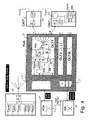
- the ATM switching center 10 the apron center 20, one of the Polling centers 40 and one of the optical Broadband network termination units 60 and one Distribution center 70, a narrowband exchange 17 and another type of broadband optical network termination unit 65.
- the apron control center 20 are an ATM switching network 21, a Narrowband multiplexer 22 and several optical Line termination units 23 shown.
- the distribution center 70 symbolically has several inputs for Video signals on, partly analog via modulators MOD and partly digitally using quadrature amplitude modulators QAM in different frequency bands implemented, via a summer be summarized and distributed after electro-optical conversion.
- the distribution services are here as CATV (cable TV), DVB (digital Video broadcasting) and nVoD (near video on demand). at near video on demand are selected programs with staggered Start times sent multiple times.
- the distribution is through here Shards shown.
- One of the optical outgoing from the splitter Fibers goes to the apron center ("Hub") 20.
- the signal is first amplified in a fiber optic amplifier FOA and over another splitter the individual line termination units (OLT1 ... OLT16) 23 forwarded.
- the ATM switching center 10 Call center 40 (VoD server) and on the other hand from Broadband Telecommunications Network 50 incoming connections to Apron headquarters 20. Except for those considered here Video-on-demand and other multimedia services (VoD, MM) are any other ATM connections.
- the ATM switching matrix 21 is provided here by way of example in order to Connections between the ATM switch and the individual To produce line termination units 23. Connections that the Serve signaling, for example, with the call center 40, pass through an ATM part and an ATM Quadrature amplitude modulator QAM and become a summer there summed up with the broadband useful signals (VoD, MM) come directly via QAM quadrature amplitude modulators. To they become electro-optical conversion in the already mentioned summer merged with the distribution service signals and further with these distributed.
- broadband and Narrow band connections 61 and 63 and 62 and 64 to transmit Between apron control center 20 and network termination unit 60 or 65 in this example, they are on separate channels, but on led common lines. In the network termination unit 60 they are not separated and therefore on a common line (coax cable) led to the participant facilities. In the network termination unit 65, however, there is a separation such that the Broadband connections related to the Distribution Service Signals together with the filters Distribution service signals are routed to the coaxial cables themselves, while the narrowband connections over a RFNT and a high-frequency network termination unit Multimedia interface MM-Intf. on separate lines MM be coupled out. About this network termination unit RFNT and one Telephone interface POTS Intf. will also be a connection for a conventional POTS (Plain Old Telephone System, "Good Old telephone ”) uncoupled.
- the narrowband switching center 17 is on the one hand with a Narrowband telecommunications network (the "normal" telephone network) and on the other hand with the narrowband multiplexer 22 in the Apron control center 20 connected. Whether the connection for analog (Good old) phone POTS or digital phone ISDN designed is or allows both, be left here. Also the question Which of the technologies for transferring POTS is not used here.
- the Multiplexer 22 connects to a narrow band part NB in the line termination units 23 ago. Each narrow band part NB is bidirectional with a high-frequency line termination unit RFLT related.
- the RFL line termination unit transmits in one of the channels described with reference to FIG. 2.
- This Channel is in the already mentioned summer with the quadrature amplitude modulated broadband useful signals and the Signaling from the ATM part of the ATM merged.
- the signal of the The opposite direction is in the wavelength-selective direction switch decoupled and after opto-electronic conversion of the High frequency line termination unit fed from where it is over the narrowband part NB and the multiplexer 22 for Narrowband switching center 17 arrives.
- Broadband network termination units 60 and 65 are also in the area between apron headquarters 20 and Broadband network termination units 60 and 65 .
- Advantageous this is when the signaling and other narrowband signals implemented to the participant on ATM and in the Broadband connections are shifted into it. Broadband and Narrow band connections are then only unidirectional. This results in a relatively simple technique.
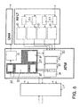
- Figure 5 shows the ATM switching network 21 and one Section of an optical line termination unit 23 with the Radio frequency line termination unit RFLT, the ATM part ATM and the Quadrature amplitude modulator QAM originating from the ATM part ATM.
- the radio frequency line termination unit RFLT has for each of the four channels each carrying a time-division multiplex stream Receiver unit 81 with channel filter and demodulator and one Adapter 82 on.
- the adaptation unit 82 is used, among other things, for Synchronization.
- ATM there is a format converter unit 83, one Decryption device 84, a buffer memory 85 ATM multiplexer 86, a control unit 87 with a Signaling monitoring circuit 88, one Signaling processing circuit 89, one Signaling circuit 90 and a time slot allocation circuit 91 and an encryption device 92.
- Format converter unit 83 converts the four Time-division multiplex data streams in 120 data streams with complete ATM cells. These data streams are in the Decryption device 84 decrypted and in the buffer memory 85 buffered so that they become a normal one in the ATM multiplexer 86 ATM data stream can be summarized. ATM cells that are identifiable not forward your cell header to the ATM switching center are not inserted into the data stream by the ATM multiplexer. In contrast, free capacities are filled with empty cells.
- the control unit 87 has the task of the invention to process back channels formed. This is particularly from the Signaling processing circuit 89 performed. Your be all capacity requirements of subscriber facilities via the signaling monitoring circuit 88 and all Capacity allocations made by the ATM switch or through these come, reported by the signaling circuit 90.
- the Processing circuit 89 thus manages the four times 30 Available time slots. Allocations or withdrawals from On the one hand, time slots are affected Subscriber device via the signaling circuit 90 in the form of ATM cells signaled and on the other hand via the Time slot allocation circuit 91 of format converter unit 83.
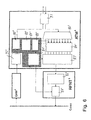
- a subscriber device is shown with reference to FIG. 6 described when the signaling is affected.
- the way of User information is not shown here.
- a Multimedia device assumes that of several remote stations Receives useful information and therefore also to several Remote stations maintain control channels.
- This facility can also be an interface circuit that is for several independent Terminal processed the signaling. As a facility for one simple end devices with only one remote station are not required in the lower one Part of the parallel processing routes.
- Figure 6 is practically the mirror image of Figure 5; each other corresponding parts are also corresponding with each other Provide reference numerals.
- Figure 6 shows a demodulator QAM 'for Quadrature amplitude modulation, one Radio frequency network termination unit RFNT 'and an ATM part ATM'.
- the Demodulator QAM 'and the network termination unit RFNT' are input or connected on the output side to the coaxial cable Coax.
- the network termination unit RFNT ' has an adapter unit 82' and one Transmitter unit 81 'with modulator and frequency converter.
- the ATM part ATM ' has an interface circuit 93, one ATM demultiplexer 86 ', an encryption device 84', one Format converter unit 83 ', a control unit 87' with a Signaling monitoring circuit 88 ', one Signaling calculation circuit 89 ', another Signaling monitoring circuit 90 'and a time slot Channel assignment circuit 91 'and one Decryption device 92 '.
Landscapes
- Engineering & Computer Science (AREA)
- Computer Networks & Wireless Communication (AREA)
- Signal Processing (AREA)
- Data Exchanges In Wide-Area Networks (AREA)
- Two-Way Televisions, Distribution Of Moving Picture Or The Like (AREA)
Claims (9)
- Système, en particulier pour des services multimédia (MM), y compris un service de vidéo à la carte (VoD), comprenant un central (20, Hub), un réseau de distribution (61, ..., 64 ; Coax) et des installations d'abonné (30) qui y sont connectés, avec des canaux à large bande (61, 62) entre le central et les installations d'abonné et des canaux retour à bande étroite (63, 64) entre les installations d'abonné et le central, dans lequel chaque installation d'abonné pouvant recevoir un canal retour (30) présente un dispositif d'émission (81', 82', 83', 86') au moyen duquel un flux de données composé de cellules ATM est formé à partir des messages à envoyer au central et converti dans un canal retour affecté à cette installation d'abonné et alimenté dans le réseau de distribution (Coax), dans lequel le central (20, Hub) présente des dispositifs de réception (RFLT, ATM) au moyen desquels respectivement le flux de données d'un canal retour est restitué comme une suite de cellules ATM et tamponné, et dans lequel le central présente un multiplexeur (86) qui regroupe les flux de données individuels en un flux de données ATM global, caractérisé en ce qu'il existe des moyens pour transmettre plusieurs canaux retour en même temps selon une technique de multiplexage temporel, la transmission de flux de cellules ATM complets s'effectuant à l'intérieur des tranches de temps respectivement attribuées avec des cellules exclusivement complètes, y compris les en-têtes de cellule.
- Installation d'abonné (30), en particulier pour des services multimédia (MM), y compris un service de vidéo à la carte (VoD), comprenant un dispositif de réception pour sélectionner l'un de plusieurs canaux à large bande et pour recevoir un flux de données à large bande transmis sur celui-ci, dans laquelle il existe un dispositif d'émission (81', 82', 83', 86'), au moyen duquel un flux de données composé de cellules ATM formé à partir des messages à envoyer à un central (20, Hub), et converti dans un canal retour à bande étroite affecté à cette installation d'abonné et alimenté dans le réseau de distribution (Coax), caractérisée en ce que le dispositif d'émission est réalisé de telle sorte qu'il émet le canal retour de telle sorte qu'il est transmis en même temps que plusieurs canaux retour d'autres installations d'abonné selon une technique de multiplexage temporel synchrone, la transmission de flux de cellules ATM complets s'effectuant à l'intérieur des tranches de temps respectivement attribuées avec des cellules exclusivement complètes, y compris les en-têtes de cellule.
- Central (20, Hub), pour un système selon la revendication 1, qui présente des dispositifs de réception (RFLT, ATM), au moyen desquels respectivement le flux de données d'un canal retour à bande étroite est restituée comme une suite de cellules ATM et tamponné, et qui présente un multiplexeur (86) qui regroupe les flux de données individuels en un flux de données ATM global, caractérisé en ce que les dispositifs de réception sont réalisés de telle sorte qu'ils restituent les canaux retour individuels à partir d'un multiplexage temporel synchrone commun à plusieurs canaux retour, le multiplexage temporel synchrone étant configuré de telle sorte qu'à l'intérieur des tranches de temps respectivement attribuées, la transmission de flux de cellules ATM complets est effectuée avec des cellules exclusivement complètes, y compris les en-têtes de cellule.
- Procédé pour un système selon la revendication 1, dans lequel des informations sont envoyées en large bande sur des canaux aller (61, 72) à des installations d'abonné (30), et dans lequel les installations d'abonné envoient sur des canaux retour à bande étroite (63, 64) des messages à un central (20, Hub), en particulier pour sélectionner les informations à envoyer sur un canal aller, dans lequel un flux de données composé de cellules ATM est formé à partir des messages respectivement d'une installation d'abonné et converti en un canal retour affecté à cette installation d'abonné et alimenté dans le réseau de distribution (61, ..., 64 ; Coax), dans lequel les flux de données respectivement d'un canal de retour sont restitués et tamponnés dans le central comme une suite de cellules ATM, et dans lequel les flux de données de tous les canaux retour sont tous regroupés en un flux de données ATM global, caractérisé en ce que plusieurs canaux retour sont transmis en même temps selon une technique de multiplexage temporel synchrone, la transmission de flux de cellules ATM complets s'effectuant à l'intérieur des tranches de temps respectivement attribuées avec des cellules exclusivement complètes, y compris les en-têtes de cellule.
- Procédé selon la revendication 4, caractérisé en ce que le nombre des canaux retour affectés à l'une des installations d'abonné est modifié de façon dynamique par le central.
- Procédé selon la revendication 5, caractérisé en ce que l'une des installations d'abonné envoie un message au central à travers un canal retour qui lui est affecté, suite auquel le central modifie le nombre des canaux retour affectés à ces installations d'abonné.
- Procédé selon la revendication 4, caractérisé en ce que le central envoie des messages aux installations d'abonné à travers des canaux aller supplémentaires.
- Procédé selon la revendication 7, caractérisé en ce que le central émet des cellules ATM de façon transparente aux installations d'abonné à travers les canaux aller supplémentaires.
- Procédé selon la revendication 4, caractérisé en ce que les messages transmis sur un canal retour sont codés.
Applications Claiming Priority (4)
| Application Number | Priority Date | Filing Date | Title |
|---|---|---|---|
| DE4432282A DE4432282A1 (de) | 1994-09-09 | 1994-09-09 | System, Teilnehmereinrichtung, Zentrale und Verfahren für Video-on-Demand-Dienst |
| DE4432282 | 1994-09-09 | ||
| DE1995127094 DE19527094A1 (de) | 1995-07-25 | 1995-07-25 | System, Teilnehmereinrichtung, Zentrale und Verfahren für Video-on-Demand-Dienst |
| DE19527094 | 1995-07-25 |
Publications (3)
| Publication Number | Publication Date |
|---|---|
| EP0701384A2 EP0701384A2 (fr) | 1996-03-13 |
| EP0701384A3 EP0701384A3 (fr) | 1998-08-12 |
| EP0701384B1 true EP0701384B1 (fr) | 2003-01-02 |
Family
ID=25940016
Family Applications (1)
| Application Number | Title | Priority Date | Filing Date |
|---|---|---|---|
| EP95113824A Expired - Lifetime EP0701384B1 (fr) | 1994-09-09 | 1995-09-02 | Système, équipement d'abonné, centrale et méthode pour vidéo à la demande |
Country Status (3)
| Country | Link |
|---|---|
| EP (1) | EP0701384B1 (fr) |
| AT (1) | ATE230548T1 (fr) |
| DE (1) | DE59510518D1 (fr) |
Families Citing this family (3)
| Publication number | Priority date | Publication date | Assignee | Title |
|---|---|---|---|---|
| US5905726A (en) * | 1996-05-21 | 1999-05-18 | Cisco Technology, Inc. | Broadband communication system having a virtual circuit space switch |
| US6014381A (en) * | 1996-09-13 | 2000-01-11 | Sony Corporation | System and method for distributing information throughout an aircraft |
| DE69816026T2 (de) | 1998-02-19 | 2004-04-22 | Alcatel | Verfahren zur Erzeugung eines Verwaltungskanals in einem optischen Netzwerk, ein Leitungsabschluss, eine erste Netzabschlusskarte und eine zweite Netzabschlusskarte zur Durchführung des Verfahrens |
Family Cites Families (2)
| Publication number | Priority date | Publication date | Assignee | Title |
|---|---|---|---|---|
| JP2938611B2 (ja) * | 1991-05-14 | 1999-08-23 | 富士通株式会社 | テレビ信号交換方式 |
| US5341474A (en) * | 1992-05-15 | 1994-08-23 | Bell Communications Research, Inc. | Communications architecture and buffer for distributing information services |
-
1995
- 1995-09-02 DE DE59510518T patent/DE59510518D1/de not_active Expired - Fee Related
- 1995-09-02 AT AT95113824T patent/ATE230548T1/de not_active IP Right Cessation
- 1995-09-02 EP EP95113824A patent/EP0701384B1/fr not_active Expired - Lifetime
Also Published As
| Publication number | Publication date |
|---|---|
| EP0701384A3 (fr) | 1998-08-12 |
| DE59510518D1 (de) | 2003-02-06 |
| ATE230548T1 (de) | 2003-01-15 |
| EP0701384A2 (fr) | 1996-03-13 |
Similar Documents
| Publication | Publication Date | Title |
|---|---|---|
| DE19841775B4 (de) | Teilnehmernetz mit optischer Faser | |
| DE69433209T2 (de) | Verteiltes telekommunikationsvermittlungssystem | |
| EP0673166B1 (fr) | Méthode de récupération d'horloge dans un récepteur pour des signaux vidéo transmis numeriquement en mode ATM dans des réseaux coaxial/fibre optique d'abbonés | |
| DE69422727T2 (de) | Steuersystem für interaktive informationsdienste | |
| DE69535205T2 (de) | Frequenzveränderliches breitbandkommunikationssystem | |
| DE69703161T2 (de) | Prüfungsanordnung für breitband fernmeldesystem | |
| DE69533538T2 (de) | Optisches Kommunikations-Zugangs-Netzwerk mit einem Multiplexer/Demultiplexer in jeder Netzabschlusseinrichtung | |
| DE69213317T2 (de) | Fernsehsignal und ATM-Zellen-Schaltungssystem | |
| DE2807986A1 (de) | Anlage fuer interaktives kabelfernsehen | |
| DE69737586T2 (de) | Durchführung von verzögerungskritischen Diensten in einem Kabel-Fernseh-System | |
| DE4242800B4 (de) | System für eine integrierte Verteilung von geschalteten Sprach- und Fernsehsignalen auf einem Koaxialkabel und mit Videosignalübertragung ausgehend von Teilnehmerstellen | |
| DE69433916T2 (de) | Verfahren und vorrichtung zur bereitstellung eines geschützten telefondienstes über ein hybrides koaxialkabelnetz | |
| DE3632047C2 (de) | Optisches Nachrichtenübertragungssystem für Schmalband- und Breitband-Nachrichtensignale | |
| EP0784891B1 (fr) | Procede de protection de donnees dans un reseau de raccordement d'abonnes pouvant fonctionner de maniere bidirectionnelle | |
| DE3146468A1 (de) | Multiplexkonzept fuer ein digitales optisches teilnehmeranschlussnetz | |
| DE4226838A1 (de) | Optisches, breitbandiges Nachrichtenübertragungssystem für Kommunikations- und Verteildienste | |
| EP0786176B1 (fr) | Reseau de raccordement d'abonnes hybride a fibres optiques et a cable coaxial | |
| JPH08116527A (ja) | インタラクティブサービス用情報の伝送制御回路装置 | |
| EP0701384A2 (fr) | Système, équipement d'abonné, centrale et méthode pour vidéo à la demande | |
| EP0839434B1 (fr) | Procede de transmission de signaux numeriques mta d'une unite de programme, en particulier de signaux de repartition video numeriques a donnees comprimees | |
| DE19527094A1 (de) | System, Teilnehmereinrichtung, Zentrale und Verfahren für Video-on-Demand-Dienst | |
| EP0760587A1 (fr) | Terminal radio utilisant un réseau hybride coax-fibre à large bande | |
| DE4406509C2 (de) | Teilnehmeranschlußnetz | |
| AT390857B (de) | Schaltungsanordnung zum vermitteln von datensignalen unterschiedlicher datensignalraten in einer datenvermittlungsanlage | |
| AU699920B2 (en) | Video-on-demand service using ATM cells |
Legal Events
| Date | Code | Title | Description |
|---|---|---|---|
| PUAI | Public reference made under article 153(3) epc to a published international application that has entered the european phase |
Free format text: ORIGINAL CODE: 0009012 |
|
| AK | Designated contracting states |
Kind code of ref document: A2 Designated state(s): AT BE CH DE ES FR GB IT LI NL SE |
|
| PUAL | Search report despatched |
Free format text: ORIGINAL CODE: 0009013 |
|
| AK | Designated contracting states |
Kind code of ref document: A3 Designated state(s): AT BE CH DE ES FR GB IT LI NL SE |
|
| 17P | Request for examination filed |
Effective date: 19981219 |
|
| 17Q | First examination report despatched |
Effective date: 19990827 |
|
| GRAG | Despatch of communication of intention to grant |
Free format text: ORIGINAL CODE: EPIDOS AGRA |
|
| GRAG | Despatch of communication of intention to grant |
Free format text: ORIGINAL CODE: EPIDOS AGRA |
|
| GRAH | Despatch of communication of intention to grant a patent |
Free format text: ORIGINAL CODE: EPIDOS IGRA |
|
| GRAH | Despatch of communication of intention to grant a patent |
Free format text: ORIGINAL CODE: EPIDOS IGRA |
|
| GRAA | (expected) grant |
Free format text: ORIGINAL CODE: 0009210 |
|
| RAP1 | Party data changed (applicant data changed or rights of an application transferred) |
Owner name: ALCATEL |
|
| AK | Designated contracting states |
Kind code of ref document: B1 Designated state(s): AT BE CH DE ES FR GB IT LI NL SE |
|
| PG25 | Lapsed in a contracting state [announced via postgrant information from national office to epo] |
Ref country code: NL Free format text: LAPSE BECAUSE OF FAILURE TO SUBMIT A TRANSLATION OF THE DESCRIPTION OR TO PAY THE FEE WITHIN THE PRESCRIBED TIME-LIMIT Effective date: 20030102 Ref country code: IT Free format text: LAPSE BECAUSE OF FAILURE TO SUBMIT A TRANSLATION OF THE DESCRIPTION OR TO PAY THE FEE WITHIN THE PRESCRIBED TIME-LIMIT;WARNING: LAPSES OF ITALIAN PATENTS WITH EFFECTIVE DATE BEFORE 2007 MAY HAVE OCCURRED AT ANY TIME BEFORE 2007. THE CORRECT EFFECTIVE DATE MAY BE DIFFERENT FROM THE ONE RECORDED. Effective date: 20030102 |
|
| REF | Corresponds to: |
Ref document number: 230548 Country of ref document: AT Date of ref document: 20030115 Kind code of ref document: T |
|
| REG | Reference to a national code |
Ref country code: GB Ref legal event code: FG4D Free format text: 20030102:NOT ENGLISH |
|
| REG | Reference to a national code |
Ref country code: CH Ref legal event code: EP |
|
| REF | Corresponds to: |
Ref document number: 59510518 Country of ref document: DE Date of ref document: 20030206 Kind code of ref document: P |
|
| PG25 | Lapsed in a contracting state [announced via postgrant information from national office to epo] |
Ref country code: SE Free format text: LAPSE BECAUSE OF FAILURE TO SUBMIT A TRANSLATION OF THE DESCRIPTION OR TO PAY THE FEE WITHIN THE PRESCRIBED TIME-LIMIT Effective date: 20030402 |
|
| GBT | Gb: translation of ep patent filed (gb section 77(6)(a)/1977) |
Effective date: 20030315 |
|
| PG25 | Lapsed in a contracting state [announced via postgrant information from national office to epo] |
Ref country code: ES Free format text: LAPSE BECAUSE OF FAILURE TO SUBMIT A TRANSLATION OF THE DESCRIPTION OR TO PAY THE FEE WITHIN THE PRESCRIBED TIME-LIMIT Effective date: 20030730 |
|
| PGFP | Annual fee paid to national office [announced via postgrant information from national office to epo] |
Ref country code: GB Payment date: 20030827 Year of fee payment: 9 |
|
| PG25 | Lapsed in a contracting state [announced via postgrant information from national office to epo] |
Ref country code: AT Free format text: LAPSE BECAUSE OF NON-PAYMENT OF DUE FEES Effective date: 20030902 |
|
| PGFP | Annual fee paid to national office [announced via postgrant information from national office to epo] |
Ref country code: DE Payment date: 20030903 Year of fee payment: 9 |
|
| PGFP | Annual fee paid to national office [announced via postgrant information from national office to epo] |
Ref country code: FR Payment date: 20030904 Year of fee payment: 9 |
|
| ET | Fr: translation filed | ||
| PG25 | Lapsed in a contracting state [announced via postgrant information from national office to epo] |
Ref country code: LI Free format text: LAPSE BECAUSE OF NON-PAYMENT OF DUE FEES Effective date: 20030930 Ref country code: CH Free format text: LAPSE BECAUSE OF NON-PAYMENT OF DUE FEES Effective date: 20030930 Ref country code: BE Free format text: LAPSE BECAUSE OF NON-PAYMENT OF DUE FEES Effective date: 20030930 |
|
| PLBE | No opposition filed within time limit |
Free format text: ORIGINAL CODE: 0009261 |
|
| STAA | Information on the status of an ep patent application or granted ep patent |
Free format text: STATUS: NO OPPOSITION FILED WITHIN TIME LIMIT |
|
| 26N | No opposition filed |
Effective date: 20031003 |
|
| BERE | Be: lapsed |
Owner name: *ALCATEL Effective date: 20030930 |
|
| REG | Reference to a national code |
Ref country code: CH Ref legal event code: PL |
|
| PG25 | Lapsed in a contracting state [announced via postgrant information from national office to epo] |
Ref country code: GB Free format text: LAPSE BECAUSE OF NON-PAYMENT OF DUE FEES Effective date: 20040902 |
|
| PG25 | Lapsed in a contracting state [announced via postgrant information from national office to epo] |
Ref country code: DE Free format text: LAPSE BECAUSE OF NON-PAYMENT OF DUE FEES Effective date: 20050401 |
|
| GBPC | Gb: european patent ceased through non-payment of renewal fee |
Effective date: 20040902 |
|
| PG25 | Lapsed in a contracting state [announced via postgrant information from national office to epo] |
Ref country code: FR Free format text: LAPSE BECAUSE OF NON-PAYMENT OF DUE FEES Effective date: 20050531 |
|
| REG | Reference to a national code |
Ref country code: FR Ref legal event code: ST |