EP0701385B1 - Lautsprechereinbau - Google Patents
Lautsprechereinbau Download PDFInfo
- Publication number
- EP0701385B1 EP0701385B1 EP95305017A EP95305017A EP0701385B1 EP 0701385 B1 EP0701385 B1 EP 0701385B1 EP 95305017 A EP95305017 A EP 95305017A EP 95305017 A EP95305017 A EP 95305017A EP 0701385 B1 EP0701385 B1 EP 0701385B1
- Authority
- EP
- European Patent Office
- Prior art keywords
- loudspeaker
- spring
- room
- mount
- frame
- Prior art date
- Legal status (The legal status is an assumption and is not a legal conclusion. Google has not performed a legal analysis and makes no representation as to the accuracy of the status listed.)
- Expired - Lifetime
Links
Images






Classifications
-
- H—ELECTRICITY
- H04—ELECTRIC COMMUNICATION TECHNIQUE
- H04R—LOUDSPEAKERS, MICROPHONES, GRAMOPHONE PICK-UPS OR LIKE ACOUSTIC ELECTROMECHANICAL TRANSDUCERS; ELECTRIC HEARING AIDS; PUBLIC ADDRESS SYSTEMS
- H04R1/00—Details of transducers, loudspeakers or microphones
- H04R1/02—Casings; Cabinets ; Supports therefor; Mountings therein
- H04R1/025—Arrangements for fixing loudspeaker transducers, e.g. in a box, furniture
-
- H—ELECTRICITY
- H04—ELECTRIC COMMUNICATION TECHNIQUE
- H04R—LOUDSPEAKERS, MICROPHONES, GRAMOPHONE PICK-UPS OR LIKE ACOUSTIC ELECTROMECHANICAL TRANSDUCERS; ELECTRIC HEARING AIDS; PUBLIC ADDRESS SYSTEMS
- H04R2201/00—Details of transducers, loudspeakers or microphones covered by H04R1/00 but not provided for in any of its subgroups
- H04R2201/02—Details casings, cabinets or mounting therein for transducers covered by H04R1/02 but not provided for in any of its subgroups
- H04R2201/021—Transducers or their casings adapted for mounting in or to a wall or ceiling
Definitions
- the present invention relates in general to loudspeaker installing and more particularly to installing loudspeakers in room boundary structures, such as walls and ceilings.
- Torsion springs typically have two stable states.
- the torsion spring mount is typically positioned in the ceiling, with the loudspeaker assembly suspended below the mount. The installer pushes the assembly toward the final mounting position. Upon reaching a transition point, the torsion spring changes from opposing assembly upward movement to aiding upward movement of the assembly into place.
- GB-A-2214553 discloses a loudspeaker fixing device and a method of mounting a loudspeaker structure according to the preambles of claims 1 and 5 respectively.
- Said loudspeaker fixing device having two projections, one of which is pivotally mounted and spring loaded. The pivotally mounted projection can be moved back against the action of the spring to enable the object to be removed from and inserted into the opening.
- US-A-3912 865 discloses a loudspeaker mounting arrangement which uses a torsion spring.
- US-A-4760510 discloses a mounting arrangement having a pair of torsion springs which are fixed to the object to be mounted.
- a mount for mounting a loudspeaker in an aperture in a room boundary structure having an outside surface away from the inside of the room comprising: a frame, and a spring having a first end attached to the frame and having a free second end, characterised in that; the frame is constructed and arranged to rest on said outside surface of the room boundary structure, and the free second end of the spring is attached, in use, to the loudspeaker, and the spring is constructed and arranged in use to exert a unidirectional force away from the inside of the room whenever the end of the spring attached to the loudspeaker is displaced towards the inside of the room.
- the frame is formed with a set of support surfaces extending from a central aperture region constructed and arranged to engage the outside surface of the room boundary structure surrounding said aperture.
- the frame may consist of two identical halves with optional locking mechanisms securing the two halves together. Alternatively a single half frame may be used.
- a method of mounting a loudspeaker structure in a room boundary structure having an outside surface away from the inside of the room including, forming an opening in said room boundary structure corresponding substantially to the cross sectional area of said loudspeaker structure when mounted in said opening, positioning a mount comprising a frame constructed and arranged to rest on said outside surface of said room boundary structure, said mount having a spring with a first end attached to said frame; characterised in that the spring has a free second end formed with an engaging structure for engaging said loudspeaker structure, and by attaching said loudspeaker structure to said engaging structure with said loudspeaker structure being inside the room, and releasing said loudspeaker structure while engaged by said engaging structure to allow said spring to pull said loudspeaker structure through said opening.
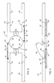
- FIGS. 1A-1D there are shown side views, partially in section of an exemplary embodiment of the invention illustrating steps in a method of mounting a loudspeaker in a ceiling according to the invention.
- Frame 22 of mount 20 is supported on ceiling 24 around hole 26.
- Spring 28 is connected to frame 22 at one end 30, is coiled about spring retainer 32, and extends distally toward hole 26 to engage loudspeaker 34.
- Distal end 36 of spring 28 is preferably hook shaped so that loop 38 on loudspeaker 34 may be easily engaged.
- a loudspeaker may be ceiling mounted by first inserting mount 20 through hole 26 in ceiling 24 and assembling it.
- Spring 28 is maintained in a compressed position during this stage by being hooked over retention tab 40 such that hook-shaped distal end 36 extends below the lower surface of ceiling 24.
- insertion can occur with spring 28 uncompressed and distal end 36 up, pulling down distal end 38 after insertion.
- loudspeaker 34 As shown in FIG. 1B, loop 38 of loudspeaker 34 then engages distal end 36 so that spring 28 supports loudspeaker 34. As shown in FIG. 1C, loudspeaker 34 is then pulled down, away from frame 22 to release spring 28 from retention tab 40. Finally, as shown in FIG. 1D, releasing loudspeaker 34 allows spring 28 to pull speaker 34 through hole 26 so that grill 42 covering loudspeaker face 44 is flush with the lower side of ceiling 24.
- a feature of the invention is that because spring 28 continuously furnishes an upward force, a person installing a loudspeaker according to the method may avoid upward pressure on the mount.
- the mount may rest freely in the ceiling because there is nothing to cause the mount to move upward during speaker installation.
- the downward force when spring 28 is released from retention tab 40 will cause mount 20 to more rigidly maintain its position.
- the same procedure may be used to install a loudspeaker driver encased within an enclosure. It may be desirable to tilt the enclosure, as shown in FIG. 2A, to move the enclosure through the hole.
- FIGS. 3 and 4 there are shown plan and elevations views respectively of an embodiment of the invention comprising a mount of two identical halves 46 shown in plan view in FIG. 5.
- frame 22 may be formed from two identical halves 46 which are held together with locking snaps 48. It is preferable for frame 22 to comprise two pieces so that it may be inserted through a small hole 26 in ceiling 24 and subsequently assembled. Frame 22 may also be assembled prior to insertion into hole 26 and may employ telescoping, folding, swiveling or other forms of support beams 50.
- Each half 46 of bracket (mount) 20 has a pair of support beams 50 which extend away from a semicircular aperture region 52 arranged to encircle hole 26 in ceiling 24. It may be desirable for support beams 50 to be of different lengths depending on the strength of the ceiling material and the available installation space. To facilitate this, each of support beams 50 may be scored at one or more locations 54 along its length (only one scoring location has been shown for simplicity).
- Lip 58 preferably extends from inside edge 60 of semicircular aperture region 52 to shield loudspeaker 34 from the inside edge of hole 26 and to prevent lateral displacement of mount 20 during installation.
- spring 28 may be coiled around spring retainer 32.
- Spring retainer 32 is a pivot point to accommodate the twisting motion of spring 28 during installation of loudspeaker 34.
- Spring 28 is preferably coiled between eight and ten times about spring retainer 32 so that spring 28 is not permanently deformed during installation. While coiled springs may be preferable, straight springs, or springs with fewer or greater numbers of coils may be used.
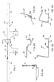
- FIGS. 6A-6C An exemplary alternative spring is shown in FIGS. 6A-6C.
- First end 30' of spring 28' is hook-shaped to replace the function of retention tab 40 in the concept shown in FIG. 5.
- distal end 36' is hook-shaped to engage a loop of loudspeaker 34; however, distal end 36' may be formed in any suitable manner for attachment to loudspeaker 34.
- distal end 36' could be formed in the shape of a loop to fit around a peg or hook on a loudspeaker.
- FIGS. 6A, 6B and 6C Spring 28' shown in its retracted position in FIGS. 6A, 6B and 6C is thus a coil 30A intermediate a first end portion extending to first end 30' and a second end portion extending to distal end 36'. Both end portions are generally L-shaped in the plane of the circular cross section 30A with the first portion being of generally U-shape in a second plane transverse to the first plane.
- FIG. 6D is an elevation view as seen in FIG. 6B but with spring 28' compressed in a typical form when positioned to retain a loudspeaker structure at distal end 36'against the ceiling.
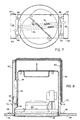
- FIGS. 7 and 8 there are shown plan and elevation views, respectively, partially in section of an alternative embodiment with the mount comprising a U-shaped beam 60 and coil spring 62.
- the bracket according to this alternative embodiment straddles hole 26 instead of extending beyond it as in the above embodiments.
- U-shaped beam 60 may be strengthened along its sides by bending a portion of the metal beam to form reinforcement bend 64.
- metal plates could be attached by any suitable method such as brazing, soldering, welding or by using bolts.
- the corners of U-shaped beam 60 may be strengthened by forming knees 66 in the metal or by attaching other suitable reinforcing members.
- Pads 68 are provided to rest on top of ceiling 24 and may be large or small depending on the amount of surface area required to distribute the weight of the bracket and loudspeaker.
- U-shaped beam 60 is preferably constructed of 20-gauge sheet metal or other similar material.
- Coil spring 62 is attached at a first end 70 to retaining hook 72. Distal end 76 of coil spring 62 is preferably connected to sleeve 78. In the extended position the upper portion of sleeve 78 engages retainer hook 80.
- Retaining hook 72 and retainer hook 80 may be formed directly from the U-shaped beam by cutting an arc or small U-shape, and bending the remaining tabular portion outward. Other well known methods of manipulating metal may also be employed to form retaining hook 72 and retainer hook 80 either directly from U-shaped beam 60 or from another piece of metal which is then attached to U-shaped beam 60.
- sleeve 78 is first extended below the lower edge of ceiling 24 and hooked on retainer hook 80 so that loop 82 on the end of sleeve 78 remains relatively stationary below ceiling 24.
- Loop 82 may also be any attachment mechanism capable of engaging a loudspeaker such as a hook or clasp.
- Coil spring 62 is then extended slightly to allow it to disengage retainer hook 80. After being disengaged, coil spring 62 pulls speaker 34 and enclosure 56 into hole 26 in ceiling 24. Speaker 34 or enclosure 56 will thereafter be held in place by friction forces and by the force exerted on it by coil spring 62.
- FIGS. 9A, 9B and 9C there are shown plan, front elevation and side elevation views of an advantageous frame structure according to the invention having a substantially semicircular front edge 71 on mounting plate 70 formed with a spacer 72 for accommodating a larger diameter driver and bracket hook 73 for receiving section 39 of the spring of FIG. 6.
- Side flanges 74 and back flange 75 are constructed and arranged to contact the outside surface of the boundary structure, such as the ceiling.
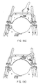
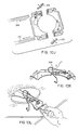
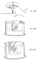
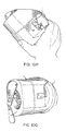
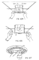
- FIGS. 10A-10H and 10J-10T there are shown illustrations helpful in installing according to the invention using another two-piece pan structure and lifting torsion springs.
- FIG. 10A shows a layout of parts helpful in understanding terminology used in describing installing.
- FIG. 10B shows a spacer 103 in place in bracket 105 at the left and being removed or installed in bracket 106 at the right.
- Spacers 103 are used to space brackets, such as 105 and 106, properly for a larger diameter driver when assembled on rails, such as 110.
- FIG. 10C shows installing a spring, such as 107 or 108, by placing a spring corner under a bracket hook, such as 73.
- FIG. 10D shows rotating the spring flat with the bracket and snapped into place.
- FIG. 10E shows the mounting system in place above a ceiling tile with the inside edges 101 and 102 closely spaced for a small opening to accommodate a speaker or enclosure of smaller diameter.
- FIG. 10F shows the mounting system in place above a ceiling tile with spacers, such as 103, preventing the inside edges 101 and 102 from closing a larger hole that accommodates a speaker or enclosure of larger diameter.
- FIG. 10G shows pulling the spring end down through the mounting hole below the ceiling tile.
- FIG. 10H shows pulling the standing part of the spring below the retaining hook 104 (also 30' in FIG. 6) and securing it under the hook.
- FIG. 10J shows the removal of rails 110 and spacers 103 for installation in structural ceilings of speakers or enclosures of any diameter.
- FIG. 10K shows preparation for installation in structural ceilings and retrofit in existing ceilings, such as of gypsum, plaster, wood or other material.
- the mounting system is then ready for speaker wiring, then installation, or speaker installation then wiring. Since wiring is well known to those skilled in the art, a specific wiring procedure is not shown. Wire and or change a tap setting as required if the speaker being installed has a number of taps.
Landscapes
- Physics & Mathematics (AREA)
- Engineering & Computer Science (AREA)
- Acoustics & Sound (AREA)
- Signal Processing (AREA)
- Details Of Audible-Bandwidth Transducers (AREA)
Claims (5)
- Einbauvorrichtung (20) zum Einbau eines Lautsprechers (34) in eine Öffnung (26) in eine Raumbegrenzungsstruktur (24), die eine außen liegende Oberfläche hat, die von der Innenseite des Raumes weg liegt, wobei die Einbauvorrichtung aufweist:einen Rahmen (22), undeine Feder (28), die ein erstes Ende hat, das an dem Rahmen (22) angebracht ist und ein freies zweites Ende hat, dadurch gekennzeichnet, daß,der Rahmen (22) derart aufgebaut und angeordnet ist, daß er auf der außen liegenden Oberfläche der Raumbegrenzungsstruktur (24) ruht unddas freie zweite Ende der Feder (28) im Gebrauch an dem Lautsprecher (34) angebracht ist und die Feder derart aufgebaut und angeordnet ist im Gebrauch, daß sie eine gleichgerichtete Kraft ausübt, die von der Innenseite des Raumes weg gerichtet ist, wann immer das Ende der an dem Lautsprecher (34) angebrachten Feder in Richtung des Inneren des Raumes versetzt wird.
- Einbauvorrichtung (20) nach Anspruch 1, wobei der Rahmen (22) mit einem Satz Tragflächen ausgebildet ist, die sich von einem zentralen Öffnungsbereich (26) erstrecken, wobei die Tragflächen derart aufgebaut und angeordnet sind, daß sie in Eingriff stehen mit bzw. anliegen an den außen liegenden Oberflächen der Raumbegrenzungsstruktur (24), die Öffnung umgebend.
- Einbauvorrichtung (20) nach Anspruch 1 oder Anspruch 2, wobei das freie zweite Ende der Feder (28) mit einer Eingriffsstruktur (36) zum Tragen einer Lautsprecherstruktur (34) ausgebildet ist.
- Einbauvorrichtung (20) gemäß einer Kombination aus Anspruch 2 und 3 und des weiteren mit einer Lautsprecherstruktur (34), wobei die Lautsprecherstruktur (34) ausgebildet ist mit einer Lautsprechereingriffsstruktur (38), zum Ineingriffgelangen mit der Eingriffsstruktur (36) des freien zweiten Endes der Feder, wobei die gleichgerichtete Kraft groß genug ist, derart, daß wenn die Tragflächen des Rahmens (22) in Eingriff gelangen mit der außen liegenden Oberfläche der Raumbegrenzungsstruktur (24) mit der sich in das Innere des Raumes erstreckenden Lautsprecherstruktur (34), die Feder (28) die Lautsprecherstruktur (34) durch den zentralen Öffnungsbereich (26) zieht, und fest in der Raumbegrenzungsstruktur (24) montiert ist.
- Verfahren zum Einbau einer Lautsprecherstruktur (34) in eine Raumbegrenzungsstruktur (24), die eine außen liegende Oberfläche hat, welche von der Innenseite des Raums wegweist, wobei das Verfahren aufweist:wobei die Einbauvorrichtung (20) eine Feder (28) mit einem an dem Rahmen angebrachten ersten Ende (30), hat, dadurch gekennzeichnet, daß die Feder (28) ein freies zweites Ende hat, das mit einer Eingriffsstruktur (36) ausgebildet ist zum Greifen der Lautsprecherstruktur (34), undAusbilden einer Öffnung (26) in der Raumbegrenzungsstruktur (24), die im wesentlichen dem Querschnittsbereich der Lautsprecherstruktur (34) entspricht, wenn sie in der Öffnung (26) montiert ist,Positionieren einer Einbauvorrichtung (20) mit einem Rahmen (22), welche derart aufgebaut und angeordnet ist, daß sie auf der außen liegenden Oberfläche der Raumbegrenzungsstruktur (24) ruht,durch Anbringen der Lautsprecherstruktur (34) an der Eingriffsstruktur (36), wobei sich die Lautsprecherstruktur (34) im Inneren des Raumes befindet, undLösen der Lautsprecherstruktur (34) während ihres Ergreifens durch die Eingriffsstruktur (36), um zu ermöglichen, daß die Feder (28) die Lautsprecherstruktur (34) durch die Öffnung (26) in der Raumbegrenzungsstruktur (24), zieht.
Applications Claiming Priority (2)
| Application Number | Priority Date | Filing Date | Title |
|---|---|---|---|
| US292722 | 1994-08-18 | ||
| US08/292,722 US5574796A (en) | 1994-08-18 | 1994-08-18 | Loudspeaker installing |
Publications (3)
| Publication Number | Publication Date |
|---|---|
| EP0701385A2 EP0701385A2 (de) | 1996-03-13 |
| EP0701385A3 EP0701385A3 (de) | 1996-11-20 |
| EP0701385B1 true EP0701385B1 (de) | 2002-09-18 |
Family
ID=23125919
Family Applications (1)
| Application Number | Title | Priority Date | Filing Date |
|---|---|---|---|
| EP95305017A Expired - Lifetime EP0701385B1 (de) | 1994-08-18 | 1995-07-19 | Lautsprechereinbau |
Country Status (4)
| Country | Link |
|---|---|
| US (1) | US5574796A (de) |
| EP (1) | EP0701385B1 (de) |
| JP (1) | JPH08172690A (de) |
| DE (1) | DE69528230T2 (de) |
Families Citing this family (31)
| Publication number | Priority date | Publication date | Assignee | Title |
|---|---|---|---|---|
| US5937073A (en) * | 1997-09-29 | 1999-08-10 | Van Gieson; David Charles | Hanging, positionable, speaker enclosure |
| US6343135B1 (en) | 1998-06-11 | 2002-01-29 | Elmark Technologies Incorporation | Retractable speaker assembly for a partition |
| US6580801B1 (en) * | 1999-03-02 | 2003-06-17 | Toa Corporation | Loudspeaker apparatus |
| US6741720B1 (en) * | 2000-04-19 | 2004-05-25 | Russound/Fmp, Inc. | In-wall loudspeaker system |
| US20020186859A1 (en) * | 2001-06-12 | 2002-12-12 | Atia Gerardo W. | Framework for home theater systems |
| US20030219133A1 (en) * | 2001-10-24 | 2003-11-27 | Acentech, Inc. | Sound masking system |
| US20030123679A1 (en) * | 2002-01-02 | 2003-07-03 | Dudleston William R. | In-wall loudspeaker |
| US6758451B2 (en) | 2002-02-15 | 2004-07-06 | Ksc Industries, Inc. | Folding speaker bracket |
| US6735321B2 (en) * | 2002-04-04 | 2004-05-11 | Bose Corporation | Loudspeaker enclosure mounting above listener |
| US6578808B1 (en) | 2002-06-13 | 2003-06-17 | Sound Advance Systems, Inc. | Mounting assembly for mounting a device in a barrier |
| US6929091B2 (en) * | 2002-10-28 | 2005-08-16 | Sound Advance Systems, Inc. | Planar diaphragm loudspeaker and related methods |
| JP3818968B2 (ja) * | 2003-01-21 | 2006-09-06 | ティーオーエー株式会社 | 天井埋込型スピーカシステム用取付補助装置 |
| US20040159490A1 (en) * | 2003-02-03 | 2004-08-19 | Marlin Bruce E. | Compact loudspeaker and control switch assembly and method for installing and adjusting a loudspeaker in a partition |
| US9181695B2 (en) * | 2004-12-22 | 2015-11-10 | Bonnie S. Schnitta | Perforation acoustic muffler assembly and method of reducing noise transmission through objects |
| US7266210B2 (en) * | 2004-04-07 | 2007-09-04 | Magnadyne Corporation | Recessed speaker box and mount |
| USD517046S1 (en) | 2004-04-07 | 2006-03-14 | Magnadyne Corporation | Mount for speaker box |
| JP2006279284A (ja) * | 2005-03-28 | 2006-10-12 | Kenwood Corp | スクリーンスピーカ |
| USD533537S1 (en) | 2005-07-28 | 2006-12-12 | Magnadyne Corporation | Partially spherical speaker enclosure and escutcheon assembly |
| US7970149B2 (en) * | 2005-07-28 | 2011-06-28 | Bby Solutions, Inc. | Audio speaker with partially spherical speaker housing and escutcheon |
| US7540460B2 (en) * | 2006-06-16 | 2009-06-02 | Britannia Investment Corporation | Mounting assembly |
| US7963076B2 (en) * | 2006-09-11 | 2011-06-21 | Dana Innovations | Devices and methods for flangeless installations |
| US20080224006A1 (en) * | 2007-03-12 | 2008-09-18 | Dana Innovations | Mounting System For Flush Assembly in Walls and Ceilings in Walls And Ceilings |
| JP5163418B2 (ja) * | 2008-10-10 | 2013-03-13 | 株式会社Jvcケンウッド | 埋込型器具及び埋込型器具の取り付け方法 |
| JP5182074B2 (ja) * | 2008-12-25 | 2013-04-10 | ヤマハ株式会社 | スピーカ保持構造 |
| GB2468645B (en) * | 2009-03-16 | 2012-06-06 | Meiloon Ind Co Ltd | Embedded spring-mounted sound box |
| GB2473229B (en) * | 2009-09-03 | 2013-07-24 | B & W Group Ltd | Loudspeaker enclosures for mounting in an aperture in a cavity wall |
| JP5906951B2 (ja) * | 2012-06-11 | 2016-04-20 | ヤマハ株式会社 | スピーカユニット |
| USD729766S1 (en) * | 2013-09-05 | 2015-05-19 | Vogel's Holding B.V. | Sound media wall mount |
| US10157604B1 (en) | 2018-01-02 | 2018-12-18 | Plantronics, Inc. | Sound masking system with improved high-frequency spatial uniformity |
| US10805699B2 (en) * | 2018-02-22 | 2020-10-13 | Mitek Corp., Inc. | L-shaped strategically hidden speaker system |
| US11215332B2 (en) * | 2019-05-02 | 2022-01-04 | Intense Lighting, Inc. | Lighting fixture having an adjustable optic system |
Family Cites Families (5)
| Publication number | Priority date | Publication date | Assignee | Title |
|---|---|---|---|---|
| US3159234A (en) * | 1962-11-15 | 1964-12-01 | Lowell Mfg Company | Securing device for loud speaker baffles |
| US3912865A (en) * | 1973-07-13 | 1975-10-14 | American Trading & Prod | Loudspeaker arrangement |
| JPS594400A (ja) * | 1982-06-30 | 1984-01-11 | Toshiba Electric Equip Corp | スピ−カ取付装置 |
| US4760510A (en) * | 1987-05-18 | 1988-07-26 | Lahti Uolevi L | Simple mounting for electrical fixture |
| GB2214553A (en) * | 1988-01-14 | 1989-09-06 | Hazel Grove Music Co Ltd | Fixing device |
-
1994
- 1994-08-18 US US08/292,722 patent/US5574796A/en not_active Expired - Lifetime
-
1995
- 1995-07-19 EP EP95305017A patent/EP0701385B1/de not_active Expired - Lifetime
- 1995-07-19 DE DE69528230T patent/DE69528230T2/de not_active Expired - Fee Related
- 1995-08-16 JP JP7208910A patent/JPH08172690A/ja active Pending
Also Published As
| Publication number | Publication date |
|---|---|
| DE69528230D1 (de) | 2002-10-24 |
| EP0701385A2 (de) | 1996-03-13 |
| DE69528230T2 (de) | 2003-01-23 |
| EP0701385A3 (de) | 1996-11-20 |
| JPH08172690A (ja) | 1996-07-02 |
| US5574796A (en) | 1996-11-12 |
Similar Documents
| Publication | Publication Date | Title |
|---|---|---|
| US5574796A (en) | Loudspeaker installing | |
| EP2045512B1 (de) | Halterung für Bauteile zur Fixierung an einem Paneel | |
| US5143339A (en) | Speaker mounting assembly | |
| JP3232103B2 (ja) | 三面体からなるブラケット | |
| CA1089618A (en) | Panel construction | |
| US6578808B1 (en) | Mounting assembly for mounting a device in a barrier | |
| CN103608531A (zh) | 竖向面板的安装硬件和安装系统 | |
| US8220757B2 (en) | Conduit hanger | |
| KR101193367B1 (ko) | 서스펜션 장치 | |
| JP2020056464A (ja) | 支持装置及びそれを用いた施工方法 | |
| JP5588799B2 (ja) | 配線・配管材引出装置及び配線・配管材引出具 | |
| EP1898016B1 (de) | Abgehängte Decke mit nach unten aufklappbaren Paneelen | |
| JP5374070B2 (ja) | 天井裏足場支持構造 | |
| JP3080575B2 (ja) | 吊下体の振れ止め構造 | |
| JPH0614827U (ja) | 天井埋込型空気調和機の据え付け装置 | |
| JPH019224Y2 (de) | ||
| JPH07260245A (ja) | 空気調和機の据付装置 | |
| JP3715076B2 (ja) | 軒樋取付構造 | |
| JP2000034837A (ja) | 天吊り機器の一点吊り工法及び揚重用器具 | |
| EP4556723A1 (de) | Nagelpistolenhalterung und verfahren | |
| JP2624070B2 (ja) | 空気調和機の据付装置 | |
| EP1460323B1 (de) | Rohrabhängung | |
| JPS62502768A (ja) | 壁又は天井板材の貫通孔に対する締結装置 | |
| JP7509804B2 (ja) | 照明器具、吊り下げ手段、及び照明器具を吊り下げ、それぞれ取り外す方法 | |
| JP3627124B2 (ja) | シャッタ−ケ−ス |
Legal Events
| Date | Code | Title | Description |
|---|---|---|---|
| PUAI | Public reference made under article 153(3) epc to a published international application that has entered the european phase |
Free format text: ORIGINAL CODE: 0009012 |
|
| AK | Designated contracting states |
Kind code of ref document: A2 Designated state(s): DE DK FR GB IT NL |
|
| PUAL | Search report despatched |
Free format text: ORIGINAL CODE: 0009013 |
|
| AK | Designated contracting states |
Kind code of ref document: A3 Designated state(s): DE DK FR GB IT NL |
|
| 17P | Request for examination filed |
Effective date: 19970509 |
|
| 17Q | First examination report despatched |
Effective date: 19990602 |
|
| GRAG | Despatch of communication of intention to grant |
Free format text: ORIGINAL CODE: EPIDOS AGRA |
|
| GRAG | Despatch of communication of intention to grant |
Free format text: ORIGINAL CODE: EPIDOS AGRA |
|
| GRAH | Despatch of communication of intention to grant a patent |
Free format text: ORIGINAL CODE: EPIDOS IGRA |
|
| GRAH | Despatch of communication of intention to grant a patent |
Free format text: ORIGINAL CODE: EPIDOS IGRA |
|
| GRAA | (expected) grant |
Free format text: ORIGINAL CODE: 0009210 |
|
| AK | Designated contracting states |
Kind code of ref document: B1 Designated state(s): DE DK FR GB IT NL |
|
| PG25 | Lapsed in a contracting state [announced via postgrant information from national office to epo] |
Ref country code: NL Free format text: LAPSE BECAUSE OF FAILURE TO SUBMIT A TRANSLATION OF THE DESCRIPTION OR TO PAY THE FEE WITHIN THE PRESCRIBED TIME-LIMIT Effective date: 20020918 Ref country code: IT Free format text: LAPSE BECAUSE OF FAILURE TO SUBMIT A TRANSLATION OF THE DESCRIPTION OR TO PAY THE FEE WITHIN THE PRESCRIBED TIME-LIMIT;WARNING: LAPSES OF ITALIAN PATENTS WITH EFFECTIVE DATE BEFORE 2007 MAY HAVE OCCURRED AT ANY TIME BEFORE 2007. THE CORRECT EFFECTIVE DATE MAY BE DIFFERENT FROM THE ONE RECORDED. Effective date: 20020918 |
|
| REG | Reference to a national code |
Ref country code: GB Ref legal event code: FG4D |
|
| REF | Corresponds to: |
Ref document number: 69528230 Country of ref document: DE Date of ref document: 20021024 |
|
| PG25 | Lapsed in a contracting state [announced via postgrant information from national office to epo] |
Ref country code: DK Free format text: LAPSE BECAUSE OF FAILURE TO SUBMIT A TRANSLATION OF THE DESCRIPTION OR TO PAY THE FEE WITHIN THE PRESCRIBED TIME-LIMIT Effective date: 20021218 |
|
| NLV1 | Nl: lapsed or annulled due to failure to fulfill the requirements of art. 29p and 29m of the patents act | ||
| ET | Fr: translation filed | ||
| PGFP | Annual fee paid to national office [announced via postgrant information from national office to epo] |
Ref country code: GB Payment date: 20030716 Year of fee payment: 9 |
|
| PGFP | Annual fee paid to national office [announced via postgrant information from national office to epo] |
Ref country code: FR Payment date: 20030718 Year of fee payment: 9 |
|
| PLBE | No opposition filed within time limit |
Free format text: ORIGINAL CODE: 0009261 |
|
| STAA | Information on the status of an ep patent application or granted ep patent |
Free format text: STATUS: NO OPPOSITION FILED WITHIN TIME LIMIT |
|
| PGFP | Annual fee paid to national office [announced via postgrant information from national office to epo] |
Ref country code: DE Payment date: 20030731 Year of fee payment: 9 |
|
| 26N | No opposition filed |
Effective date: 20030619 |
|
| PG25 | Lapsed in a contracting state [announced via postgrant information from national office to epo] |
Ref country code: GB Free format text: LAPSE BECAUSE OF NON-PAYMENT OF DUE FEES Effective date: 20040719 |
|
| PG25 | Lapsed in a contracting state [announced via postgrant information from national office to epo] |
Ref country code: DE Free format text: LAPSE BECAUSE OF NON-PAYMENT OF DUE FEES Effective date: 20050201 |
|
| GBPC | Gb: european patent ceased through non-payment of renewal fee |
Effective date: 20040719 |
|
| PG25 | Lapsed in a contracting state [announced via postgrant information from national office to epo] |
Ref country code: FR Free format text: LAPSE BECAUSE OF NON-PAYMENT OF DUE FEES Effective date: 20050331 |
|
| REG | Reference to a national code |
Ref country code: FR Ref legal event code: ST |