EP0701465B1 - Sprühdüse - Google Patents
Sprühdüse Download PDFInfo
- Publication number
- EP0701465B1 EP0701465B1 EP94916157A EP94916157A EP0701465B1 EP 0701465 B1 EP0701465 B1 EP 0701465B1 EP 94916157 A EP94916157 A EP 94916157A EP 94916157 A EP94916157 A EP 94916157A EP 0701465 B1 EP0701465 B1 EP 0701465B1
- Authority
- EP
- European Patent Office
- Prior art keywords
- sprinkler
- outlet orifice
- outlet
- deflector
- extinguishing liquid
- Prior art date
- Legal status (The legal status is an assumption and is not a legal conclusion. Google has not performed a legal analysis and makes no representation as to the accuracy of the status listed.)
- Expired - Lifetime
Links
- 239000007788 liquid Substances 0.000 claims abstract description 20
- 230000002093 peripheral effect Effects 0.000 claims 1
- 238000010586 diagram Methods 0.000 description 12
- 238000000889 atomisation Methods 0.000 description 6
- 230000015572 biosynthetic process Effects 0.000 description 4
- 238000009434 installation Methods 0.000 description 4
- 239000003795 chemical substances by application Substances 0.000 description 3
- XLYOFNOQVPJJNP-UHFFFAOYSA-N water Substances O XLYOFNOQVPJJNP-UHFFFAOYSA-N 0.000 description 3
- 239000002184 metal Substances 0.000 description 2
- 239000003708 ampul Substances 0.000 description 1
- 239000011521 glass Substances 0.000 description 1
- 230000003993 interaction Effects 0.000 description 1
- 230000002262 irrigation Effects 0.000 description 1
- 238000003973 irrigation Methods 0.000 description 1
- 239000003595 mist Substances 0.000 description 1
- 239000002245 particle Substances 0.000 description 1
- 238000004080 punching Methods 0.000 description 1
- 239000007787 solid Substances 0.000 description 1
- 230000003068 static effect Effects 0.000 description 1
- 238000011144 upstream manufacturing Methods 0.000 description 1
Images

Classifications
-
- B—PERFORMING OPERATIONS; TRANSPORTING
- B05—SPRAYING OR ATOMISING IN GENERAL; APPLYING FLUENT MATERIALS TO SURFACES, IN GENERAL
- B05B—SPRAYING APPARATUS; ATOMISING APPARATUS; NOZZLES
- B05B1/00—Nozzles, spray heads or other outlets, with or without auxiliary devices such as valves, heating means
- B05B1/26—Nozzles, spray heads or other outlets, with or without auxiliary devices such as valves, heating means with means for mechanically breaking-up or deflecting the jet after discharge, e.g. with fixed deflectors; Breaking-up the discharged liquid or other fluent material by impinging jets
- B05B1/262—Nozzles, spray heads or other outlets, with or without auxiliary devices such as valves, heating means with means for mechanically breaking-up or deflecting the jet after discharge, e.g. with fixed deflectors; Breaking-up the discharged liquid or other fluent material by impinging jets with fixed deflectors
- B05B1/265—Nozzles, spray heads or other outlets, with or without auxiliary devices such as valves, heating means with means for mechanically breaking-up or deflecting the jet after discharge, e.g. with fixed deflectors; Breaking-up the discharged liquid or other fluent material by impinging jets with fixed deflectors the liquid or other fluent material being symmetrically deflected about the axis of the nozzle
-
- A—HUMAN NECESSITIES
- A62—LIFE-SAVING; FIRE-FIGHTING
- A62C—FIRE-FIGHTING
- A62C31/00—Delivery of fire-extinguishing material
- A62C31/02—Nozzles specially adapted for fire-extinguishing
-
- B—PERFORMING OPERATIONS; TRANSPORTING
- B05—SPRAYING OR ATOMISING IN GENERAL; APPLYING FLUENT MATERIALS TO SURFACES, IN GENERAL
- B05B—SPRAYING APPARATUS; ATOMISING APPARATUS; NOZZLES
- B05B1/00—Nozzles, spray heads or other outlets, with or without auxiliary devices such as valves, heating means
- B05B1/02—Nozzles, spray heads or other outlets, with or without auxiliary devices such as valves, heating means designed to produce a jet, spray, or other discharge of particular shape or nature, e.g. in single drops, or having an outlet of particular shape
-
- B—PERFORMING OPERATIONS; TRANSPORTING
- B05—SPRAYING OR ATOMISING IN GENERAL; APPLYING FLUENT MATERIALS TO SURFACES, IN GENERAL
- B05B—SPRAYING APPARATUS; ATOMISING APPARATUS; NOZZLES
- B05B1/00—Nozzles, spray heads or other outlets, with or without auxiliary devices such as valves, heating means
- B05B1/02—Nozzles, spray heads or other outlets, with or without auxiliary devices such as valves, heating means designed to produce a jet, spray, or other discharge of particular shape or nature, e.g. in single drops, or having an outlet of particular shape
- B05B1/04—Nozzles, spray heads or other outlets, with or without auxiliary devices such as valves, heating means designed to produce a jet, spray, or other discharge of particular shape or nature, e.g. in single drops, or having an outlet of particular shape in flat form, e.g. fan-like, sheet-like
- B05B1/042—Outlets having two planes of symmetry perpendicular to each other, one of them defining the plane of the jet
Definitions
- the invention concerns a sprinkler for mounting on a pipe in which a fire extinguishing liquid is fed under pressure.
- a fixed pipe installation having such a sprinkler is used e.g. in buildings and ships where the sprinkler is provided with a release mechanism which keeps the outlet orifice of the sprinkler closed in the static state, and which opens the outlet orifice of the sprinkler when actuated in case of a fire so that the fire-extinguishing liquid can flow out.
- the sprinkler has a deflector arranged downstream of the outlet orifice, and when the outflowing liquid hits the deflector, the liquid is spread in the form of drops and mist with a view to extinguishing a fire.
- a sprinkler of this type, but without an actuation mechanism may e.g. be used in irrigation systems.
- the sprinkler For use in smaller, rectangular rooms or corridors in which the sprinkler is arranged centrally in the room and near the ceiling, it is desirable to adapt the spread diagram of the sprinkler to the geometry of the room so that the sprinkler spreads the extinguishing agent most in the longitudinal direction of the room, while spreading transverse to the longitudinal direction is restricted.
- US-A-4 279 309 and US-A-4 585 069 show a sprinkler having an elongate outlet orifice which gives an elongate spread diagram.
- the outlet orifice may advantageously be made star-shaped, and an oval star shape moreover results in an elongate spread pattern.
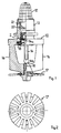
- Figures 1 and 5 do not show an embodiment of the invention but are for illustrative purpose.
- Fig. 1 shows a sprinkler having a sprinkler housing 10 of metal.
- the upper end of the sprinkler housing 10 has a cylindrical threaded part 11 by means of which the sprinkler can be screwed into a pipe installation.
- the threaded part 11 is upwardly provided with a filter or a net 12 to prevent solid particles from the pipe installation from flowing into the sprinkler.
- An outlet nozzle 20 is arranged downstream of the filter 12 and in the cylindrical bore in the threaded part 11, said nozzle having an upwardly open, hemispherical cavity 21 whose bottom is formed with an outlet orifice 22, which will be described later.
- the sprinkler housing 10 Downstream of the outlet nozzle 20 the sprinkler housing 10 has an outlet 2 which is closed by a plug 13, which is kept in position by a glass ampoule or bulb 14, whose upstream end 14a engages the plug 13, and whose downstream end 14b engages a screw 15, which is screwed into the downstream end of the sprinkler housing 10 carried by two arms 16.
- a deflector 17 Outwardly on its downstream end the sprinkler housing has a deflector 17 of a known structure, which is shown clearly in fig. 2.
- the bulb 14 keeps the plug 13 in position in the outlet orifice 12 by means of the pressure from the screw 15 so that the plug 13 fits tightly in the outlet 2, thereby making the sprinkler tight.
- the bulb 14 is of a known structure and contains a medium which expands when heated, and when a predetermined critical temperature is exceeded, the bulb 14 bursts, thereby releasing the plug 13, and owing to the pressure in the pipe system the plug 13 will be forced out and thereby provide free discharge of water or extinguishing liquid from the pipe system.
- the extinguishing liquid then flows through the outlet orifice 22 in the outlet nozzle 20 and hits the deflector 17, which spreads the outflowing water in a known manner.
- the outlet orifice 22 has a cross-section which is defined by two semi-circular arcs 23a and 23b of uniform diameter, which are interconnected by two parallel lines 24a and 24b, so that the cross-section of the outlet orifice 22 is oval.
- Fig. 6 shows an outlet nozzle 30 having a cross-shaped outlet orifice 32.
- the outlet orifice 32 consists of two slots 33 and 34 which are of different length and intersect each other at a right angle.
- the outlet nozzle 30 is disc-shaped and made by punching of a metal plate.
- the cross-shaped outlet orifice 32 has a cross-section which causes a significant pressure drop for the outflowing extinguishing liquid, and this results in a certain atomization or drop formation of the extinguishing liquid before it hits the deflector 17.
- the slot 33 is longer than the slot 34, which results in an elongate spread pattern as is the case for the oval outlet orifice 22 shown in figure 4.
- the outlet orifice may also consist of three or more intersecting slots which form a star, which, together with the deflector, gives the optimal atomisation or drop formation of the extinguishing liquid.
- a star-shaped outlet orifice can be made "oval” in that it consists of slots of different length, and the spread diagram can hereby be made correspondingly elongate.
- the deviation of the spread diagram from circular may likewise be varied by varying the proportion between the major axis and minor axis of the outlet orifice, and the outlet orifice may be formed as an elongate, narrow gap or as two or more parallel or intersecting slots with a view to obtaining special spread diagrams.
- the outlet nozzle may have several smaller outlet orifices which are not necessarily parallel and hereby additionally form the spread diagram and increase the atomization of the extinguishing liquid before it hits the deflector.
- a suitable shape of the outlet orifice can even provide such a degree of atomization and spreading of the extinguishing liquid that a deflector is superfluous.
Landscapes
- Health & Medical Sciences (AREA)
- Public Health (AREA)
- Business, Economics & Management (AREA)
- Emergency Management (AREA)
- Fire-Extinguishing By Fire Departments, And Fire-Extinguishing Equipment And Control Thereof (AREA)
- Nozzles (AREA)
Claims (4)
- Sprühdüse mit einer Auslaßöffnung (30) für eine Flüssigkeit und einem stromabwärts von der Auslaßöffnung angeordnetem Umlenkelement (17) zum Versprühen einer aus der Auslaßöffnung fließenden Flüssigkeit, dadurch gekennzeichnet, daß die Auslaßöffnung (30) durch mindestens zwei längliche Schlitze (32, 33) gebildet ist.
- Sprühdüse nach Anspruch 1, dadurch gekennzeichnet, daß die Schlitze (32, 33) sich jeweils schneiden.
- Sprühdüse nach Anspruch 2, dadurch gekennzeichnet, daß die Schlitze (32, 33) unterschiedlich lang sind.
- Sprühdüse nach Anspruch 3, dadurch gekennzeichnet, daß die äußeren Enden der Schlitze auf einer ovalen, geschlossenen Kurve angeordnet sind.
Applications Claiming Priority (3)
| Application Number | Priority Date | Filing Date | Title |
|---|---|---|---|
| DK93578A DK57893D0 (da) | 1993-05-18 | 1993-05-18 | Sprinkler |
| DK578/93 | 1993-05-18 | ||
| PCT/DK1994/000195 WO1994026354A1 (en) | 1993-05-18 | 1994-05-18 | A sprinkler |
Publications (2)
| Publication Number | Publication Date |
|---|---|
| EP0701465A1 EP0701465A1 (de) | 1996-03-20 |
| EP0701465B1 true EP0701465B1 (de) | 1997-07-16 |
Family
ID=8095154
Family Applications (1)
| Application Number | Title | Priority Date | Filing Date |
|---|---|---|---|
| EP94916157A Expired - Lifetime EP0701465B1 (de) | 1993-05-18 | 1994-05-18 | Sprühdüse |
Country Status (4)
| Country | Link |
|---|---|
| EP (1) | EP0701465B1 (de) |
| DE (1) | DE69404308T2 (de) |
| DK (1) | DK57893D0 (de) |
| WO (1) | WO1994026354A1 (de) |
Families Citing this family (1)
| Publication number | Priority date | Publication date | Assignee | Title |
|---|---|---|---|---|
| US5829532A (en) | 1997-03-07 | 1998-11-03 | Central Sprinkler Corporation | Low pressure, early suppression fast response sprinklers |
Family Cites Families (4)
| Publication number | Priority date | Publication date | Assignee | Title |
|---|---|---|---|---|
| US3830434A (en) * | 1973-02-20 | 1974-08-20 | Morris G | Multiple outlet adjustable sprinkler head |
| US4279309A (en) * | 1979-06-29 | 1981-07-21 | Grinnell Fire Protection Systems Company, Inc. | Sprinkler head with noncircular throat |
| US4585069A (en) * | 1984-10-18 | 1986-04-29 | Grinnell Fire Protection Systems Company, Inc. | Liquid discharge nozzle |
| CA2070383C (en) * | 1990-10-12 | 2000-04-11 | Takaharu Tasaki | Foaming nozzle for sprayer |
-
1993
- 1993-05-18 DK DK93578A patent/DK57893D0/da unknown
-
1994
- 1994-05-18 DE DE69404308T patent/DE69404308T2/de not_active Expired - Lifetime
- 1994-05-18 EP EP94916157A patent/EP0701465B1/de not_active Expired - Lifetime
- 1994-05-18 WO PCT/DK1994/000195 patent/WO1994026354A1/en not_active Ceased
Also Published As
| Publication number | Publication date |
|---|---|
| DK57893D0 (da) | 1993-05-18 |
| DE69404308D1 (de) | 1997-08-21 |
| WO1994026354A1 (en) | 1994-11-24 |
| EP0701465A1 (de) | 1996-03-20 |
| DE69404308T2 (de) | 1997-10-30 |
Similar Documents
| Publication | Publication Date | Title |
|---|---|---|
| EP2012881B1 (de) | Horizontaler seitenwandsprinkler mit erweiterter abdeckung | |
| RU2424838C1 (ru) | Спринклерная установка пожаротушения | |
| US7658231B2 (en) | Residential fire sprinkler | |
| US7096964B2 (en) | Sprinklers | |
| AU2000263289A1 (en) | Sprinklers | |
| RU2647104C2 (ru) | Мелкодисперсный распылитель жидкости | |
| US6481644B1 (en) | Device by sprinkler nozzle | |
| RU2512869C1 (ru) | Установка пожаротушения водяной завесой | |
| EP0701465B1 (de) | Sprühdüse | |
| RU2258551C1 (ru) | Способ создания распыленного потока жидкости и спринклер | |
| US20210260423A1 (en) | Sprinkler Head | |
| RU2577652C1 (ru) | Спринклерная установка пожаротушения | |
| CN1503699A (zh) | 散布小水滴用的喷洒机喷嘴 | |
| RU2660858C1 (ru) | Спринклер для системы пожаротушения | |
| RU2641476C1 (ru) | Спринклерная установка пожаротушения | |
| RU2660859C1 (ru) | Спринклерная установка пожаротушения | |
| RU2636722C1 (ru) | Спринклер | |
| JPH0332380Y2 (de) | ||
| RU2532726C1 (ru) | Система пожаротушения с дренчерным оросителем | |
| HK1128437B (en) | Extended coverage horizontal sidewall sprinkler | |
| JPS6249868A (ja) | 消火・冷却用ヘツド |
Legal Events
| Date | Code | Title | Description |
|---|---|---|---|
| PUAI | Public reference made under article 153(3) epc to a published international application that has entered the european phase |
Free format text: ORIGINAL CODE: 0009012 |
|
| 17P | Request for examination filed |
Effective date: 19951214 |
|
| AK | Designated contracting states |
Kind code of ref document: A1 Designated state(s): DE DK FR GB |
|
| GRAG | Despatch of communication of intention to grant |
Free format text: ORIGINAL CODE: EPIDOS AGRA |
|
| 17Q | First examination report despatched |
Effective date: 19960710 |
|
| GRAH | Despatch of communication of intention to grant a patent |
Free format text: ORIGINAL CODE: EPIDOS IGRA |
|
| GRAH | Despatch of communication of intention to grant a patent |
Free format text: ORIGINAL CODE: EPIDOS IGRA |
|
| GRAA | (expected) grant |
Free format text: ORIGINAL CODE: 0009210 |
|
| AK | Designated contracting states |
Kind code of ref document: B1 Designated state(s): DE DK FR GB |
|
| PG25 | Lapsed in a contracting state [announced via postgrant information from national office to epo] |
Ref country code: DK Effective date: 19970716 |
|
| REF | Corresponds to: |
Ref document number: 69404308 Country of ref document: DE Date of ref document: 19970821 |
|
| ET | Fr: translation filed | ||
| PLBE | No opposition filed within time limit |
Free format text: ORIGINAL CODE: 0009261 |
|
| STAA | Information on the status of an ep patent application or granted ep patent |
Free format text: STATUS: NO OPPOSITION FILED WITHIN TIME LIMIT |
|
| 26N | No opposition filed | ||
| REG | Reference to a national code |
Ref country code: GB Ref legal event code: IF02 |
|
| PGFP | Annual fee paid to national office [announced via postgrant information from national office to epo] |
Ref country code: FR Payment date: 20110523 Year of fee payment: 18 |
|
| PGFP | Annual fee paid to national office [announced via postgrant information from national office to epo] |
Ref country code: GB Payment date: 20110518 Year of fee payment: 18 |
|
| PGFP | Annual fee paid to national office [announced via postgrant information from national office to epo] |
Ref country code: DE Payment date: 20110511 Year of fee payment: 18 |
|
| GBPC | Gb: european patent ceased through non-payment of renewal fee |
Effective date: 20120518 |
|
| REG | Reference to a national code |
Ref country code: FR Ref legal event code: ST Effective date: 20130131 |
|
| REG | Reference to a national code |
Ref country code: DE Ref legal event code: R119 Ref document number: 69404308 Country of ref document: DE Effective date: 20121201 |
|
| PG25 | Lapsed in a contracting state [announced via postgrant information from national office to epo] |
Ref country code: GB Free format text: LAPSE BECAUSE OF NON-PAYMENT OF DUE FEES Effective date: 20120518 Ref country code: FR Free format text: LAPSE BECAUSE OF NON-PAYMENT OF DUE FEES Effective date: 20120531 |
|
| PG25 | Lapsed in a contracting state [announced via postgrant information from national office to epo] |
Ref country code: DE Free format text: LAPSE BECAUSE OF NON-PAYMENT OF DUE FEES Effective date: 20121201 |