EP0701633B1 - Verfahren und vorrichtung zur herstellung eines verbundbauteils und seine verwendung - Google Patents
Verfahren und vorrichtung zur herstellung eines verbundbauteils und seine verwendung Download PDFInfo
- Publication number
- EP0701633B1 EP0701633B1 EP94918369A EP94918369A EP0701633B1 EP 0701633 B1 EP0701633 B1 EP 0701633B1 EP 94918369 A EP94918369 A EP 94918369A EP 94918369 A EP94918369 A EP 94918369A EP 0701633 B1 EP0701633 B1 EP 0701633B1
- Authority
- EP
- European Patent Office
- Prior art keywords
- metal
- metal plate
- composite component
- foam
- metal foam
- Prior art date
- Legal status (The legal status is an assumption and is not a legal conclusion. Google has not performed a legal analysis and makes no representation as to the accuracy of the status listed.)
- Expired - Lifetime
Links
- 239000002131 composite material Substances 0.000 title claims abstract description 39
- 238000000034 method Methods 0.000 title claims abstract description 24
- 238000004519 manufacturing process Methods 0.000 title abstract description 24
- 239000006262 metallic foam Substances 0.000 claims description 49
- 229910052751 metal Inorganic materials 0.000 claims description 45
- 239000002184 metal Substances 0.000 claims description 45
- 238000005520 cutting process Methods 0.000 claims description 7
- 239000003349 gelling agent Substances 0.000 claims description 3
- 238000005266 casting Methods 0.000 claims description 2
- 230000008021 deposition Effects 0.000 claims 2
- 230000002093 peripheral effect Effects 0.000 claims 1
- 229910052782 aluminium Inorganic materials 0.000 abstract description 33
- XAGFODPZIPBFFR-UHFFFAOYSA-N aluminium Chemical compound [Al] XAGFODPZIPBFFR-UHFFFAOYSA-N 0.000 abstract description 33
- 239000006260 foam Substances 0.000 abstract description 22
- 239000004411 aluminium Substances 0.000 abstract 7
- 238000004026 adhesive bonding Methods 0.000 abstract 1
- 238000004049 embossing Methods 0.000 description 12
- 239000010410 layer Substances 0.000 description 10
- 230000001105 regulatory effect Effects 0.000 description 10
- 238000010924 continuous production Methods 0.000 description 3
- 238000001816 cooling Methods 0.000 description 3
- 238000010438 heat treatment Methods 0.000 description 3
- 238000010521 absorption reaction Methods 0.000 description 2
- 239000000853 adhesive Substances 0.000 description 2
- 230000001070 adhesive effect Effects 0.000 description 2
- 230000015572 biosynthetic process Effects 0.000 description 2
- 238000009792 diffusion process Methods 0.000 description 2
- 238000005192 partition Methods 0.000 description 2
- 229910000838 Al alloy Inorganic materials 0.000 description 1
- 239000011248 coating agent Substances 0.000 description 1
- 238000000576 coating method Methods 0.000 description 1
- 238000007688 edging Methods 0.000 description 1
- 238000009499 grossing Methods 0.000 description 1
- 230000001788 irregular Effects 0.000 description 1
- 239000000463 material Substances 0.000 description 1
- 229910001092 metal group alloy Inorganic materials 0.000 description 1
- 239000011148 porous material Substances 0.000 description 1
- 238000010079 rubber tapping Methods 0.000 description 1
- 230000035939 shock Effects 0.000 description 1
- 239000007787 solid Substances 0.000 description 1
- 238000007711 solidification Methods 0.000 description 1
- 230000008023 solidification Effects 0.000 description 1
- 239000002344 surface layer Substances 0.000 description 1
- 238000009966 trimming Methods 0.000 description 1
Images
Classifications
-
- B—PERFORMING OPERATIONS; TRANSPORTING
- B32—LAYERED PRODUCTS
- B32B—LAYERED PRODUCTS, i.e. PRODUCTS BUILT-UP OF STRATA OF FLAT OR NON-FLAT, e.g. CELLULAR OR HONEYCOMB, FORM
- B32B15/00—Layered products comprising a layer of metal
- B32B15/04—Layered products comprising a layer of metal comprising metal as the main or only constituent of a layer, which is next to another layer of the same or of a different material
- B32B15/046—Layered products comprising a layer of metal comprising metal as the main or only constituent of a layer, which is next to another layer of the same or of a different material of foam
-
- B—PERFORMING OPERATIONS; TRANSPORTING
- B22—CASTING; POWDER METALLURGY
- B22F—WORKING METALLIC POWDER; MANUFACTURE OF ARTICLES FROM METALLIC POWDER; MAKING METALLIC POWDER; APPARATUS OR DEVICES SPECIALLY ADAPTED FOR METALLIC POWDER
- B22F7/00—Manufacture of composite layers, workpieces, or articles, comprising metallic powder, by sintering the powder, with or without compacting wherein at least one part is obtained by sintering or compression
- B22F7/002—Manufacture of composite layers, workpieces, or articles, comprising metallic powder, by sintering the powder, with or without compacting wherein at least one part is obtained by sintering or compression of porous nature
- B22F7/004—Manufacture of composite layers, workpieces, or articles, comprising metallic powder, by sintering the powder, with or without compacting wherein at least one part is obtained by sintering or compression of porous nature comprising at least one non-porous part
- B22F7/006—Manufacture of composite layers, workpieces, or articles, comprising metallic powder, by sintering the powder, with or without compacting wherein at least one part is obtained by sintering or compression of porous nature comprising at least one non-porous part the porous part being obtained by foaming
-
- B—PERFORMING OPERATIONS; TRANSPORTING
- B32—LAYERED PRODUCTS
- B32B—LAYERED PRODUCTS, i.e. PRODUCTS BUILT-UP OF STRATA OF FLAT OR NON-FLAT, e.g. CELLULAR OR HONEYCOMB, FORM
- B32B15/00—Layered products comprising a layer of metal
- B32B15/01—Layered products comprising a layer of metal all layers being exclusively metallic
- B32B15/016—Layered products comprising a layer of metal all layers being exclusively metallic all layers being formed of aluminium or aluminium alloys
-
- B—PERFORMING OPERATIONS; TRANSPORTING
- B32—LAYERED PRODUCTS
- B32B—LAYERED PRODUCTS, i.e. PRODUCTS BUILT-UP OF STRATA OF FLAT OR NON-FLAT, e.g. CELLULAR OR HONEYCOMB, FORM
- B32B15/00—Layered products comprising a layer of metal
- B32B15/20—Layered products comprising a layer of metal comprising aluminium or copper
-
- B—PERFORMING OPERATIONS; TRANSPORTING
- B32—LAYERED PRODUCTS
- B32B—LAYERED PRODUCTS, i.e. PRODUCTS BUILT-UP OF STRATA OF FLAT OR NON-FLAT, e.g. CELLULAR OR HONEYCOMB, FORM
- B32B5/00—Layered products characterised by the non- homogeneity or physical structure, i.e. comprising a fibrous, filamentary, particulate or foam layer; Layered products characterised by having a layer differing constitutionally or physically in different parts
- B32B5/18—Layered products characterised by the non- homogeneity or physical structure, i.e. comprising a fibrous, filamentary, particulate or foam layer; Layered products characterised by having a layer differing constitutionally or physically in different parts characterised by features of a layer of foamed material
-
- C—CHEMISTRY; METALLURGY
- C22—METALLURGY; FERROUS OR NON-FERROUS ALLOYS; TREATMENT OF ALLOYS OR NON-FERROUS METALS
- C22C—ALLOYS
- C22C1/00—Making non-ferrous alloys
- C22C1/08—Alloys with open or closed pores
-
- C—CHEMISTRY; METALLURGY
- C22—METALLURGY; FERROUS OR NON-FERROUS ALLOYS; TREATMENT OF ALLOYS OR NON-FERROUS METALS
- C22C—ALLOYS
- C22C1/00—Making non-ferrous alloys
- C22C1/08—Alloys with open or closed pores
- C22C1/083—Foaming process in molten metal other than by powder metallurgy
-
- B—PERFORMING OPERATIONS; TRANSPORTING
- B32—LAYERED PRODUCTS
- B32B—LAYERED PRODUCTS, i.e. PRODUCTS BUILT-UP OF STRATA OF FLAT OR NON-FLAT, e.g. CELLULAR OR HONEYCOMB, FORM
- B32B2311/00—Metals, their alloys or their compounds
- B32B2311/24—Aluminium
Definitions
- the invention relates to a method for producing a composite component according to the preamble of claim 1 and to an apparatus for performing the method and to the use of a composite component.
- JP-OS 1-275831 A describes the production of an aluminum composite component: Thin aluminum foam disks are cut from an aluminum foam block and largely glued to an aluminum sheet.
- the known manufacturing process for a generic composite component is very complex: in a first step, an aluminum foam block is produced, from which flat aluminum disks are separated in a second step. In the third step, these panes are glued to the aluminum sheet. Since the surfaces of the aluminum foam sheets to be bonded have open pores due to the cutting process, considerable amounts of adhesive are required, which also contributes to an increase in the weight of the composite component.
- the method described is only suitable for the production of flat composite components.
- the object of the invention is therefore to provide a method and a device for simple, fast and inexpensive To provide production of a composite component, so that the disadvantages of the prior art can be avoided.
- Claims 8 to 10 relate to devices according to the invention for carrying out the method.
- the main idea of the invention is to produce the connection between the metal plate and the metal foam in the manner of a diffusion adhesion by applying hot, not preformed metal foam directly to the metal plate. It makes sense to couple the production of the composite component directly to the production of the metal foam.
- This measure does not first produce a block of metal foam which, after it has cooled down, has to be cut again into metal foam disks and glued to the metal plate in a separate operation, but instead foam production and the production of the composite component take place directly on top of one another.
- a simple and economical method is available with which generic composite components can be produced without the use of an adhesive.
- the metal foam is still in a formable state, preferably in the molten state.
- Dough metal foam (“semisolid foam”) can also be processed.
- Metal " in connection with the invention is to be understood as a metal alloy with viscosity-increasing components which serve to stabilize the molten foam structure.
- the "metal plates” of the subject matter of the invention are not necessarily flat structures, but can be shaped as desired within wide limits in terms of their dimensions and shape, as is the case, for. B. at by deep drawing preformed metallic body parts is the case.
- the development of the invention according to claim 2 ensures a secure and resilient connection between the metal foam and the metal plate, in that the preheating of the metal plate avoids cooling of the metal foam at the contact surface with the metal plate, which hinders the diffusion adhesion.
- the embodiment of the invention according to claim 3 also creates the conditions for connecting the two component parts.
- the gelling agent used reduces the surface tensions and may also cause the metal plate surface to dissolve.
- the metal foam in a continuous process of an edge of the metal plate, the z. B. can be designed as an endless sheet of metal, which eliminates the need to insert and remove individual metal plates.
- the foam production can z. B. by the method described in US 4,973,358 A.
- the regulating device With the method further developed according to claim 5, it is possible to adjust the thickness of the metal foam layer individually in a simple manner, the regulating device ensuring a constant thickness and a smoothed surface.
- the heating of the regulating device (claim 6) facilitates the production of a flat surface of the metal foam layer.
- the regulating device it is possible to achieve a closed metal foam surface.
- the finished composite component can thus also be cleaned on the metal foam side in a simple manner or provided with additional attachments.
- To cool the metal foam it is possible, for example, to provide a cooling device with air outlet openings facing the metal foam downstream of the regulating device.
- the improved manufacturing method according to claim 7 is particularly economical since the composite components do not have to be removed from the device for embossing and inserted into a separate embossing device.
- the embossing of the composite components can take place individually at the right temperature, either by heating or cooling between the regulating and embossing device.
- the use of an embossing / cutting tool enables combined embossing and trimming in one operation, which reduces manufacturing costs and duration and minimizes component tolerances.
- the composite component can be embossed with the desired contour on both the metal plate and the metal foam side.
- the method according to claim 8 uses an easy-to-use mold that works on the principle of a cake pan.
- the metal plate itself forms the lower part of the mold and becomes part of the later composite component.
- the upper part of the mold can be lowered into the lateral edging part of the mold.
- This principle allows great freedom with regard to the shape of the composite component: wall thicknesses and contours can be chosen as freely as possible.
- the wall thickness of the metal foam can be constant or variable over the area of the metal plate.
- the metal plate can be flat or preformed.
- the upper part can be congruent to the metal plate or can have any shape.
- the metal foam By applying force to the upper part in the direction of the metal plate, the metal foam can be slightly compressed, at least in its regions close to the surface, which results in a closed surface.
- a closed surface of the metal foam layer can also be achieved by heating the individual mold parts.
- the metal plate in particular must be preheated for the purpose of a secure connection.
- the metal foam required for loading the mold can be produced, for example, by the process described in WO 91/01387 A1. Alternatively, metal foam can also be skimmed off from the crucible of US Pat. No. 4,973,358 A and introduced into the casting mold. In addition, other manufacturing processes for providing metal foam are also possible.
- the device according to claim 9 enables a continuous and automated manufacturing process in which, for example, metal sheet is coated from the coil quickly, inexpensively and with consistent quality with metal foam. By eliminating inlay work, as would be the case with individual metal plates, a high output is possible.
- Deflection and transport device can, for example, be combined and designed as a driven roller arranged in the area of the feed device. It is also conceivable to use a deflection roller in the area of the feed device and a large-area conveyor belt which also serves to guide the metal sheet.
- a device is known from US Pat. No.
- a device in which the continuous production of composite components in a continuous production process is possible by the lining up of the two stations (coating, embossing). Eliminating the need for inserting and removing work between the stations results in a reduction in manufacturing time, which means high quantities and low manufacturing costs. Manufacturing can be largely automated.
- the embossing and cutting device must be moved in its lowered position with the transport device for the composite component, for. B. by snapping into place on lateral guides of the transport device.
- Claim 11 describes a particularly advantageous use of a composite component: by combining the two components, on the one hand, a paintable body shell is available with the metal sheet of almost any shape.
- the metal foam on the inside on the other hand, can perform various tasks, e.g. B. Increasing the stiffness of the outer skin or soundproofing.
- the use of metal foam means that there is no need for a stiffening interior body panel, which is complex to manufacture in many cases and is characterized by a relatively high weight.
- the stiffening metal foam can take on noise protection tasks.
- Possible applications are, for example, composite components according to the invention as front and rear flaps, sunroof covers, etc.
- the metal foam is non-combustible.
- composite components according to the invention can, however, also be used inside the vehicle, for example as a partition between the engine and interior.
- the metal foam is primarily used for sound absorption.
- Composite components in the front and rear of the vehicle with correspondingly thick metal foam layers are particularly suitable for shock absorption through plastic deformation of the metal foam.
- the attachment of panels or attachments to the metal foam layer is possible in a particularly simple manner, for. B. by self-tapping screws.
- dowel-like fasteners which interact with their barbs with the numerous, sharp-edged, thin partitions of the bubble-like cavities of the metal foam, are particularly suitable.
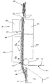
- the single figure shows a device for producing a composite component in side view in a highly schematic representation.
- a crucible 1 there is an aluminum alloy 2 in the molten state.
- a gas is added to the surface of the molten aluminum 2 from a gas bubble penetrated surface layer 3 made of aluminum foam 4.
- the aluminum foam 4 is brought to a transport roller 6 which functions as a deflection and transport device via a conveyor device 5.
- the transport roller 6 deflects an aluminum sheet 7 and guides it to a horizontal sheet guide 8.
- the aluminum foam 4 is applied to the top 9 of the aluminum sheet 7 via the conveyor device 5.
- a regulating device 10 arranged above the transport roller 6 with a wiping edge 11 facing the conveying device 5 adjusts the thickness of the aluminum foam layer 12.
- the regulating device 10 has openings 13a and 13b for the supply of cold or warm air.
- An embossing and cutting device 14 connects to the regulating device 10. It consists of an embossing die 15 arranged below the aluminum sheet 7, an embossing die 16 arranged above the aluminum foam layer 12 and a cutting tool 17.
- Both the transport of the aluminum sheet 7 and the transport of the aluminum foam 4 take place continuously.
- the aluminum sheet 7 is heated by means not shown both in front of the transport roller 6 and on the transport roller 6 and in the sheet guide 8.
- the aluminum foam 4 is applied to the aluminum sheet 7 moving away under the conveyor 5.
- the regulating device 10 limits the height of the aluminum foam layer 12. It is also heatable, so that the top 18 of the aluminum foam layer 12 becomes as smooth as possible. Either warm air to further support the surface smoothing or cold air to accelerate the solidification of the aluminum foam layer 12 can be introduced through the openings 13a of the regulating device 10.
- the supply of gelling agent through the openings 13b facilitates the formation of a smooth upper side 18.
- the contour of the composite component 19 can be determined by the shape of the embossing mold 15 and the stamp 16.
- the cutting tool 17 separates the finished composite components 19 from the continuous aluminum sheet 7.
Landscapes
- Chemical & Material Sciences (AREA)
- Engineering & Computer Science (AREA)
- Materials Engineering (AREA)
- Mechanical Engineering (AREA)
- Metallurgy (AREA)
- Organic Chemistry (AREA)
- Composite Materials (AREA)
- Manufacturing & Machinery (AREA)
- Laminated Bodies (AREA)
- Pressure Welding/Diffusion-Bonding (AREA)
Abstract
Description
- Die Erfindung bezieht sich auf ein Verfahren zur Herstellung eines Verbundbauteils nach dem Oberbegriff des Anspruchs 1 sowie auf eine Vorrichtung zur Durchführung des Verfahrens sowie auf die Verwendung eines Verbundbauteils.
- Die JP-OS 1-275831 A beschreibt die Herstellung eines Aluminium-Verbundbauteils: Von einem Aluminiumschaumblock werden dünne Aluminiumschaumscheiben abgeschnitten und mit einem Aluminiumblech großflächig verklebt.
Das bekannte Herstellungsverfahren für ein gattungsgemäßes Verbundbauteil ist sehr aufwendig: In einem ersten Schritt wird ein Aluminiumschaumblock hergestellt, von dem in einem zweiten Schritt ebene Aluminiumscheiben abgetrennt werden. Im dritten Schritt werden diese Scheiben mit dem Aluminiumblech verklebt. Da die zu verklebenden Oberflächen der Aluminiumschaumscheiben aufgrund des Schneidevorgangs offene Poren aufweisen, sind beträchtliche Mengen an Kleber erforderlich, was auch zu einer Gewichtserhöhung des Verbundbauteils beiträgt. Außerdem eignet sich das beschriebene Verfahren nur zur Herstellung ebener Verbundbauteile. - Aufgabe der Erfindung ist es daher, ein Verfahren und eine Vorrichtung zur einfachen, schnellen und kostengünstigen Herstellung eines Verbundbauteils bereitzustellen, so daß die Nachteile des Standes der Technik vermieden werden können.
- Diese Aufgabe wird durch die kennzeichnenden Merkmale des Anspruchs 1 gelöst. Die Ansprüche 8 bis 10 betreffen erfindungsgemäße Vorrichtungen zur Durchführung des Verfahrens.
Kerngedanke der Erfindung ist es, die Verbindung zwischen Metallplatte und Metallschaum nach Art einer Diffusionshaftung herzustellen, indem heißer, nicht vorgeformter Metallschaum direkt auf die Metallplatte aufgebracht wird. Hierbei bietet es sich an, die Herstellung des Verbundbauteils unmittelbar an die Herstellung des Metallschaums zu koppeln. Durch diese Maßnahme wird nicht zuerst ein Metallschaumblock hergestellt, der nach seiner Abkühlung wieder in Metallschaumscheiben zerschnitten und in einem getrennten Arbeitsgang mit der Metallplatte verklebt werden muß, sondern Schaumherstellung und Herstellung des Verbundbauteils erfolgen unmittelbar aufeinander. Hierdurch steht ein einfaches und wirtschaftliches Verfahren zur Verfügung, mit dem ohne Einsatz eines Klebemittels gattungsgemäße Verbundbauteile hergestellt werden können.
Der Metallschaum befindet sich erfindungsgemäß in einem noch formbaren Zustand, bevorzugt im schmelzflüssigen Zustand. Auch teigiger Metallschaum ("semisolid foam") kann verarbeitet werden.
Unter "Metall..." ist im Zusammenhang mit der Erfindung eine Metallegierung mit viskositätssteigernden Komponenten, die zur Stabilisierung der schmelzflüssigen Schaumstruktur dienen, zu verstehen.
Die "Metallplatten" des Erfindungsgegenstandes sind nicht notwendigerweise ebene Gebilde, sondern können innerhalb weiter Grenzen in ihren Abmessungen und in ihrer Form beliebig geformt sein, wie dies z. B. bei durch Tiefziehen vorgeformten metallischen Karosseriebauteilen der Fall ist. - Die Weiterbildung der Erfindung nach Anspruch 2 gewährleistet eine sichere und belastbare Verbindung zwischen Metallschaum und Metallplatte, indem durch die Vorwärmung der Metallplatte eine die Diffusionshaftung behindernde Abkühlung des Metallschaums an der Berührungsfläche mit der Metallplatte vermieden wird.
- Auch die Ausgestaltung der Erfindung nach Anspruch 3 schafft die Voraussetzung für eine Verbindung der beiden Bauteilkomponenten. Das eingesetzte Geliermittel setzt die Oberflächenspannungen herab und bewirkt unter Umständen auch ein Anlösen der Metallplattenoberfläche.
- Durch die vorteilhafte Ausführung der Erfindung nach Anspruch 4 steht ein großtechnisch anwendbares Herstellverfahren zur Verfügung, mit dem in kostengünstiger Weise die automatisierte Serienproduktion von Verbundbauteilen ermöglicht wird. Hierbei wird der Metallschaum in einem kontinuierlichen Prozeß einer Kante der Metallplatte, die z. B. als endloses Metallblech ausgeführt sein kann, zugeführt, wodurch ein Einlegen und Entnehmen einzelner Metallplatten entfällt.
Die Schaumherstellung kann hierbei z. B. nach dem in der US 4,973,358 A beschriebenen Verfahren erfolgen. - Mit dem nach Anspruch 5 weitergebildeten Verfahren ist es möglich, in einfacher Weise die Dicke der Metallschaumschicht individuell einzustellen, wobei die Regulierungseinrichtung für eine gleichbleibende Dicke und eine geglättete Oberfläche sorgt.
Die Beheizung der Regulierungseinrichtung (Anspruch 6) erleichtert die Herstellung einer ebenen Oberfläche der Metallschaumschicht. Je nach Temperatur und Gestaltung der Regulierungseinrichtung ist es möglich, eine geschlossene Metallschaumoberfläche zu erzielen. Somit kann das fertige Verbundbauteil auch auf der Metallschaumseite in einfacher Weise gereinigt oder mit weiteren Anbauteilen versehen werden.
Zur Abkühlung des Metallschaums ist es beispielsweise möglich, nachgeschaltet an die Regulierungseinrichtung eine Abkühlvorrichtung mit dem Metallschaum zugewandten Luftaustrittsöffnungen vorzusehen. - Das verbesserte Herstellverfahren nach Anspruch 7 ist besonders wirtschaftlich, da die Verbundbauteile zum Verprägen nicht aus der Vorrichtung entnommen und in eine separate Prägevorrichtung eingelegt werden müssen. Außerdem kann die Verprägung der Verbundbauteile je nach eingesetztem Material und gestellten Anforderungen individuell bei der richtigen Temperatur erfolgen, indem zwischen Regulierungs- und Prägeeinrichtung entweder beheizt oder abgekühlt wird. Durch den Einsatz eines Präge-/Schneidwerkzeuges ist ein kombiniertes Verprägen und Beschneiden in einem Arbeitsgang möglich, wodurch Herstellungskosten und -dauer sinken und Bauteiltoleranzen minimiert werden können. Dem Verbundbauteil kann sowohl auf der Metallplatten- als auch der Metallschaumseite die gewünschte Kontur aufgeprägt werden.
- Das Verfahren gemäß Anspruch 8 verwendet eine einfach zu handhabende Gußform, die nach dem Prinzip einer Kuchenform arbeitet. Die Metallplatte selbst bildet das Unterteil der Form und wird zum Bestandteil des späteren Verbundbauteils. Das Oberteil der Form ist in das seitliche Einfassungsteil der Form absenkbar. Dieses Prinzip gewährt eine große Freiheit hinsichtlich der Formgebung des Verbundbauteils: Wandstärken und Konturen können weitestgehend frei gewählt werden. Mit dem beschriebenen Verfahren können sowohl einfache als auch komplizierte Verbundbauteile hergestellt werden. Die Wandstärke des Metallschaumes kann hierbei konstant oder über der Flächenerstreckung der Metallplatte variabel sein. Die Metallplatte kann eben oder vorgeformt sein. Das Oberteil kann kongruent zur Metallplatte oder beliebig geformt sein. Durch Kraftbeaufschlagung des Oberteils in Richtung auf die Metallplatte kann der Metallschaum zumindest in seinen oberflächennahen Bereichen geringfügig verdichtet werden, woraus sich eine geschlossene Oberfläche ergibt. Auch durch Erwärmung der einzelnen Gußformteile kann eine geschlossene Oberfläche der Metallschaumschicht erzielt werden. Insbesondere die Metallplatte ist zum Zwecke einer sicheren Verbindung vorzuwärmen.
Der für die Beschickung der Gußform erforderliche Metallschaum kann beispielsweise durch das in der WO 91/01387 A1 beschriebene Verfahren hergestellt werden. Alternativ kann Metallschaum auch aus dem Schmelztiegel der US 4,973,358 A abgeschöpft und in die Gußform eingebracht werden. Daneben kommen auch andere Herstellverfahren zur Bereitstellung von Metallschaum in Frage. - Die Vorrichtung nach Anspruch 9 ermöglicht einen kontinuierlichen und automatisierten Herstellungsprozeß, bei dem beispielsweise Metallblech vom Coil schnell, kostengünstig und in gleichbleibender Qualität mit Metallschaum beschichtet wird. Durch den Entfall von Einlegearbeiten, wie dies bei einzelnen Metallplatten der Fall wäre, ist ein hoher Ausstoß möglich.
Umlenk- und Transporteinrichtung können beispielsweise zusammengefaßt und als im Bereich der Zuführeinrichtung angeordnete angetriebene Rolle ausgebildet sein. Ebenso ist es denkbar, eine Umlenkrolle im Bereich der Zuführeinrichtung und ein großflächiges, auch der Führung des Metallbleches dienendes Transportband zu verwenden. Zwar ist aus der US 4,973,358 A eine Vorrichtung bekannt, die mit einem Transportband arbeitet, jedoch dient diese Vorrichtung lediglich der Herstellung von Metallschaum: Der auf das hitzebeständige Transportband aufgebrachte Metallschaum erstarrt unter Bildung einer unregelmäßigen Oberfläche mit zunehmender Entfernung vom Schmelztiegel und wird im festen Zustand vom Transportband zur weiteren Bearbeitung abgenommen. Im Unterschied hierzu handelt es sich beim Erfindungsgegenstand um eine Vorrichtung zur Herstellung eines kompletten Verbundbauteils, wobei das Prinzip der Bereitstellung des Metallschaums gemäß dem US-Patent durchaus eingesetzt werden kann. Generell sind jedoch auch andere Verfahren zur Metallschaumherstellung möglich. - Durch die Weiterbildung der Erfindung nach Anspruch 10 steht eine Vorrichtung zur Verfügung, bei der durch die Aneinanderreihung der beiden Stationen (Beschichtung, Verprägung) die kontinuierliche Herstellung von Verbundbauteilen in einem durchlaufenden Produktionsprozeß möglich ist. Durch den Entfall von Einlege- und Entnahmearbeiten zwischen den Stationen ergibt sich eine Verkürzung der Herstellzeit, somit hohe erreichbare Stückzahlen und niedrige Herstellkosten. Die Herstellung kann weitestgehend automatisiert erfolgen.
Die Präge- und Schneideeinrichtung muß in ihrer abgesenkten Position mit der Transporteinrichtung für das Verbundbauteil mitbewegt werden, z. B. durch Einrasten beim Aufsetzen auf seitliche Führungen der Transporteinrichtung. - Anspruch 11 beschreibt eine besonders vorteilhafte Verwendung eines Verbundbauteils: Durch die Kombination der beiden Komponenten steht einerseits mit dem Metallblech eine lackierbare Karosserieaußenhaut nahezu beliebiger Formgebung zur Verfügung. Der Metallschaum auf der Innenseite kann andererseits verschiedene Aufgaben erfüllen, z. B. Erhöhung der Steifigkeit der Außenhaut oder Schalldämmung. So kann beispielsweise durch den Einsatz von Metallschaum ein versteifendes Karosserieinnenblech entfallen, das in vielen Fällen aufwendig in der Herstellung ist und sich durch relativ hohes Gewicht auszeichnet. Gleichzeitig kann der versteifende Metallschaum Schallschutzaufgaben übernehmen. Mögliche Anwendungen sind beispielsweise erfindungsgemäße Verbundbauteile als Front- und Heckklappen, Schiebedachdeckel, etc. Im Falle der Frontklappe ist weiterhin von Vorteil, daß der Metallschaum nicht brennbar ist.
Neben Außenhautteilen können erfindungsgemäße Verbundbauteile jedoch auch im Fahrzeuginneren verwendet werden, beispielsweise als Trennwand zwischen Motor- und Innenraum. Hier kommen dem Metallschaum in erster Linie Schallabsorptionsaufgaben zu.
Verbundbauteile im Fahrzeugfront- und Fahrzeugheckbereich mit entsprechend dicken Metallschaumschichten eignen sich in besonderer Weise zur Stoßabsorption durch plastische Verformung des Metallschaums.
Die Befestigung von Verkleidungen oder Anbauteilen an der Metallschaumschicht ist in besonders einfacher Weise möglich, z. B. durch Blechschrauben. Auch dübelartige Befestigungselemente, die mit ihren Widerhaken mit den zahlreichen, scharfkantigen, dünnen Trennwänden der bläschenartigen Hohlräume des Metallschaumes zusammenwirken, eignen sich in besonderer Weise. - Ein mögliches Ausführungsbeispiel der Erfindung wird anhand der Zeichnung näher erläutert. Die einzige Figur zeigt eine Vorrichtung zur Herstellung eines Verbundbauteils in der Seitenansicht in stark schematisierter Darstellung.
- In einem Schmelztiegel 1 befindet sich eine Aluminiumlegierung 2 im schmelzflüssigen Zustand. Durch Zuführen eines Gases setzt sich an der Oberfläche der Aluminiumschmelze 2 eine gasblasendurchsetzte Oberflächenschicht 3 aus Aluminiumschaum 4 ab. Über eine Fördereinrichtung 5 wird der Aluminiumschaum 4 zu einer als Umlenk- und Transporteinrichtung fungierenden Transportrolle 6 gebracht. Die Transportrolle 6 lenkt ein Aluminiumblech 7 um und führt es einer horizontalen Blechführung 8 zu. Über die Fördereinrichtung 5 wird der Aluminiumschaum 4 auf die Oberseite 9 des Aluminiumblechs 7 aufgebracht. Eine oberhalb der Transportrolle 6 angeordnete Regulierungseinrichtung 10 mit einer der Fördereinrichtung 5 zugewandten Abstreifkante 11 stellt die Dicke der Aluminiumschaumschicht 12 ein. Die Regulierungseinrichtung 10 weist Öffnungen 13a und 13b für die Zuführung von kalter oder warmer Luft auf. An die Regulierungseinrichtung 10 schließt sich eine Präge- und Schneideeinrichtung 14 an. Sie besteht aus einer unterhalb des Aluminiumbleches 7 angeordneten Prägeform 15, einem oberhalb der Aluminiumschaumschicht 12 angeordneten Prägestempel 16 und einem Schneidwerkzeug 17.
- Sowohl der Transport des Aluminiumbleches 7 als auch der Transport des Aluminiumschaums 4 erfolgen kontinuierlich. Hierbei wird das Aluminiumblech 7 durch nicht dargestellte Einrichtungen sowohl vor der Transportrolle 6 als auch an der Transportrolle 6 und in der Blechführung 8 beheizt. Am Ende der Fördereinrichtung 5 wird der Aluminiumschaum 4 auf das sich unter der Fördereinrichtung 5 wegbewegende Aluminiumblech 7 aufgebracht. Die Regulierungseinrichtung 10 begrenzt die Höhe der Aluminiumschaumschicht 12. Sie ist ebenfalls beheizbar, so daß die Oberseite 18 der Aluminiumschaumschicht 12 möglichst glattflächig wird. Durch die Öffnungen 13a der Regulierungseinrichtung 10 kann entweder warme Luft zur weiteren Unterstützung der Oberflächenglättung oder kalte Luft zur Beschleunigung des Erstarrens der Aluminiumschaumschicht 12 eingeleitet werden. Die Zuführung von Geliermittel durch die Öffnungen 13b erleichtert die Bildung einer glatten Oberseite 18.
- Durch die Formgebung von Prägeform 15 und Prägestempel 16 kann die Kontur des Verbundbauteils 19 bestimmt weren. Das Schneidwerkzeug 17 trennt vom durchlaufenden Aluminiumblech 7 die fertigen Verbundbauteile 19 ab.
Claims (11)
- Verfahren zur Herstellung eines Verbundbauteils (19), bei dem auf zumindest einer Metallplatte (7) zumindest eine Metallschaumschicht (12) angeordnet ist,
dadurch gekennzeichnet, daß der Metallschaum (4) im formbaren Zustand auf die Metallplatte (7) aufgebracht wird. - Verfahren zur Herstellung eines Verbundbauteils nach Anspruch 1,
dadurch gekennzeichnet, daß die Metallplatte vor dem Aufbringen des Metallschaums (4) erwärmt wird. - Verfahren zur Herstellung eines Verbundbauteils nach Anspruch 1 und/oder Anspruch 2,
dadurch gekennzeichnet, daß die dem Metallschaum (4) zugewandte Oberfläche der Metallplatte vor dem Aufbringen des Metallschaums (4) mit einem Geliermittel versehen wird. - Verfahren zur Herstellung eines Verbundbauteils nach wenigstens einem der vorgenannten Ansprüche,
dadurch gekennzeichnet, daß der Metallschaum (4) über eine Zuführeinrichtung (5) kontinuierlich der Metallplatte (7) zugeführt wird, wobei die Zuführung in einer Richtung etwa parallel zur Ebene der Metallplatte (7) erfolgt und die Metallplatte (7) von der Zuführeinrichtung (5) wegbewegt wird. - Verfahren zur Herstellung eines Verbundbauteils nach Anspruch 4,
dadurch gekennzeichnet, daß im Bereich der Zuführeinrichtung (5) oberhalb der Metallplatte (7) eine Regulierungseinrichtung (10) zur Schichtdickeneinstellung des Metallschaums (4) vorgesehen ist. - Verfahren zur Herstellung eines Verbundbauteils nach Anspruch 5,
dadurch gekennzeichnet, daß die Regulierungseinrichtung (10) beheizt ist. - Verfahren zur Herstellung eines Verbundbauteils nach wenigstens einem der vorgenannten Ansprüche,
dadurch gekennzeichnet, daß Metallplatte und Metallschaumschicht (12) unmittelbar nach ihrer Zusammenführung gemeinsam verprägt werden. - Verfahren zur Herstellung eines Verbundbauteils nach wenigstens einem der Ansprüche 1 bis 3,dadurch gekennzeichnet, daß eine Gußform verwendet wird, die im wesentlichen aus einem absenkbaren Oberteil und einem das Oberteil einhüllenden, umlaufenden Einfassungsteil besteht, wobeiin einem ersten Schritt das sich zumindest etwa lotrecht zur Metallplatte erstreckende Einfassungsteil auf die Metallplatte abdichtend aufgesetzt bzw. die Metallplatte in das Einfassungsteil abdichtend eingesetzt wird,in einem zweiten Schritt der Metallschaum auf die Metallplatte aufgebracht wird undin einem dritten Schritt das Oberteil in Richtung auf die Metallplatte abgesenkt wird.
- Vorrichtung zur Durchführung des Verfahrens nach Anspruch 1, bei dem der Metallschaum über eine Zuführeinrichtung kontinuierlich einer sich von der Zuführeinrichtung wegbewegenden und als endloses Metallblech ausgebildeten Metallplatte zugeführt wird, mit einer im Bereich der Zuführeinrichtung (5) angeordneten Umlenkeinrichtung (6) für das Metallblech sowie mit einer Transporteinrichtung (6) für die Bewegung des Metallbleches weg von der Zuführeinrichtung (5).
- Vorrichtung nach Anspruch 9,
wobei sich an die Zuführeinrichtung (5) eine Präge- und/oder Schneideeinrichtung (14) anschließt, die oberhalb des durchlaufenden Metallbleches (7) angeordnet ist und in Richtung lotrecht zum Metallblech (7) bewegbar ist. - Verwendung eines Verbundbauteils-bestehend aus einer Metallplatte und einer Metallschaumschicht und hergestellt nach einem Verfahren gemäß wenigstens einem der Ansprüche 1 bis 7 - als Karosseriebauteil für ein Kraftfahrzeug, wobei die der Metallschaumschicht (12) abgewandte Seite der Metallplatte (7) einen Teil der Karosserieaußenfläche bildet.
Applications Claiming Priority (3)
| Application Number | Priority Date | Filing Date | Title |
|---|---|---|---|
| DE4318540A DE4318540A1 (de) | 1993-06-04 | 1993-06-04 | Verfahren und Vorrichtung zur Herstellung eines Verbundbauteils |
| DE4318540 | 1993-06-04 | ||
| PCT/EP1994/001682 WO1994029490A1 (de) | 1993-06-04 | 1994-05-26 | Verfahren und vorrichtung zur herstellung eines verbundbauteils |
Publications (2)
| Publication Number | Publication Date |
|---|---|
| EP0701633A1 EP0701633A1 (de) | 1996-03-20 |
| EP0701633B1 true EP0701633B1 (de) | 1997-01-08 |
Family
ID=6489603
Family Applications (1)
| Application Number | Title | Priority Date | Filing Date |
|---|---|---|---|
| EP94918369A Expired - Lifetime EP0701633B1 (de) | 1993-06-04 | 1994-05-26 | Verfahren und vorrichtung zur herstellung eines verbundbauteils und seine verwendung |
Country Status (5)
| Country | Link |
|---|---|
| EP (1) | EP0701633B1 (de) |
| CA (1) | CA2164441C (de) |
| DE (2) | DE4318540A1 (de) |
| NO (1) | NO309488B1 (de) |
| WO (1) | WO1994029490A1 (de) |
Families Citing this family (25)
| Publication number | Priority date | Publication date | Assignee | Title |
|---|---|---|---|---|
| DE19653149A1 (de) * | 1996-12-19 | 1998-06-25 | Bayerische Motoren Werke Ag | Werkstück aus einem Leichtbau-Werkstoff und Verfahren zur Herstellung des Werkstückes |
| DE19705836B4 (de) * | 1997-02-15 | 2006-09-21 | Continental Teves Ag & Co. Ohg | Bremsbacke und Verfahren zu ihrer Herstellung |
| DE19749294C1 (de) * | 1997-11-07 | 1999-04-01 | Daimler Benz Ag | Karosseriestruktur mit wenigstens einer Querverbindung |
| AU1694999A (en) * | 1998-06-02 | 1999-12-20 | Bo Young Hur | Multi-purpose, aluminum foam-based soundproof panel |
| KR100322253B1 (ko) * | 1998-06-02 | 2002-05-13 | 위성갑 | 허니콤-발포알루미늄방음벽용패널 |
| DE19854173C2 (de) | 1998-11-24 | 2000-11-23 | Fritz Michael Streuber | Metallschaumformkörper |
| DE19854175C1 (de) | 1998-11-24 | 2000-03-23 | Fritz Michael Streuber | Metallschaumfügeverfahren |
| DE19908867A1 (de) * | 1999-03-01 | 2000-09-07 | Arved Huebler | Verbundkörper sowie Verfahren zum Herstellen eines Verbundkörpers |
| WO2000073694A1 (de) * | 1999-05-26 | 2000-12-07 | Thermotite As | Stahlrohr mit wärmeisolierung für tiefseerohrleitungen und verfahren zu seiner herstellung |
| DE19925840B4 (de) * | 1999-06-01 | 2004-07-08 | Brose Fahrzeugteile Gmbh & Co. Kg, Coburg | Karosserieteil für Kraftfahrzeuge sowie Verfahren zu dessen Herstellung |
| DE19941199A1 (de) * | 1999-08-30 | 2001-03-01 | Arved Huebler | Verfahren zur Herstellung eines Verbundkörper-Bauteiles sowie Verbundkörper-Bauteil |
| DE19951097C1 (de) * | 1999-10-23 | 2001-06-13 | Daimler Chrysler Ag | Verstärkungselement aus Metallschaum und Verfahren zu seiner Herstellung |
| US6481911B1 (en) | 1999-11-24 | 2002-11-19 | Fritz Michael Streuber | Jointing method for joining preformed bodies |
| DE10042569C1 (de) * | 2000-08-25 | 2002-04-04 | Christian Steglich | Verfahren und Einrichtung zur Herstellung von Verbundwerkstoffen mit einem Kern aus Metallschaum |
| CN1314533C (zh) * | 2000-11-30 | 2007-05-09 | 北京有色金属研究总院 | 一种复合泡沫金属及其制备方法 |
| DE10104338A1 (de) * | 2001-02-01 | 2002-08-08 | Goldschmidt Ag Th | Herstellung flächiger, metallischer Integralschäume |
| DE10127716A1 (de) * | 2001-06-07 | 2002-12-12 | Goldschmidt Ag Th | Verfahren zur Herstellung von Metall/Metallschaum-Verbundbauteilen |
| AT501676B1 (de) | 2004-06-02 | 2007-01-15 | Miba Gleitlager Gmbh | Verfahren zum herstellen eines schichtverbundwerkstoffes |
| DE102006007665A1 (de) * | 2006-02-18 | 2007-08-23 | Bayerische Motoren Werke Ag | Kraftfahrzeug mit zumindest einem Deckel |
| RU2359783C1 (ru) * | 2007-10-18 | 2009-06-27 | Открытое акционерное общество Акционерная холдинговая компания "Всероссийский научно-исследовательский и проектно-конструкторский институт металлургического машиностроения имени академика Целикова" (ОАО АХК "ВНИИМЕТМАШ") | Способ и линия производства листов пеноалюминия |
| DE102010051139A1 (de) * | 2010-11-11 | 2012-05-16 | Bayerische Motoren Werke Aktiengesellschaft | Belastbare Stützstruktur, die mit einem Bauteil eines Kraftfahrzeugs verbunden ist |
| DE102012023876A1 (de) | 2012-12-06 | 2013-07-18 | Daimler Ag | Verbundbauteil für ein Kraftfahrzeug |
| DE202013103272U1 (de) | 2013-07-22 | 2014-10-23 | Wegener International Gmbh | Heizeinrichtung für die Plastifizierung von Werkstücken aus einem thermoplastischen Kunststoff |
| CN103805796A (zh) * | 2013-10-23 | 2014-05-21 | 芜湖长启炉业有限公司 | 陶瓷不粘铝辊 |
| AT522145B1 (de) * | 2019-02-14 | 2021-05-15 | Eh Holding Gmbh | Wagenkastenelement für einen Zugswaggon |
Family Cites Families (9)
| Publication number | Priority date | Publication date | Assignee | Title |
|---|---|---|---|---|
| DE1114329B (de) * | 1954-01-13 | 1961-09-28 | Deutsche Edelstahlwerke Ag | Verfahren zur Herstellung von metallischen, poroes gesinterten Blechen, Formteilen u. dgl. |
| US3336134A (en) * | 1960-12-14 | 1967-08-15 | Gen Electric | Foam material |
| US3704193A (en) * | 1970-10-05 | 1972-11-28 | Ethyl Corp | Method of strain-hardening foamed metal |
| US3929425A (en) * | 1973-02-26 | 1975-12-30 | Ethyl Corp | Foamed metal bodies |
| DE2737248C2 (de) * | 1977-08-18 | 1985-09-19 | MTU Motoren- und Turbinen-Union München GmbH, 8000 München | Bauteil hoher Festigkeit mit komplizierter geometrischer Form und Verfahren zu dessen Herstellung |
| US4738896A (en) * | 1986-09-26 | 1988-04-19 | Advanced Technology Materials, Inc. | Sol gel formation of polysilicate, titania, and alumina interlayers for enhanced adhesion of metal films on substrates |
| NO172697C (no) * | 1989-07-17 | 1993-08-25 | Norsk Hydro As | Fremgangsmaate ved fremstilling av partikkelforsterket metallskum og resulterende produkt |
| US4973358A (en) * | 1989-09-06 | 1990-11-27 | Alcan International Limited | Method of producing lightweight foamed metal |
| JP3349186B2 (ja) * | 1993-01-12 | 2002-11-20 | 富士重工業株式会社 | 発泡アルミニウム製品の製造法 |
-
1993
- 1993-06-04 DE DE4318540A patent/DE4318540A1/de not_active Withdrawn
-
1994
- 1994-05-26 EP EP94918369A patent/EP0701633B1/de not_active Expired - Lifetime
- 1994-05-26 DE DE59401552T patent/DE59401552D1/de not_active Expired - Fee Related
- 1994-05-26 CA CA002164441A patent/CA2164441C/en not_active Expired - Fee Related
- 1994-05-26 WO PCT/EP1994/001682 patent/WO1994029490A1/de not_active Ceased
-
1995
- 1995-11-30 NO NO954865A patent/NO309488B1/no unknown
Also Published As
| Publication number | Publication date |
|---|---|
| DE4318540A1 (de) | 1994-12-08 |
| NO309488B1 (no) | 2001-02-05 |
| WO1994029490A1 (de) | 1994-12-22 |
| NO954865L (no) | 1995-11-30 |
| CA2164441C (en) | 2005-05-24 |
| CA2164441A1 (en) | 1994-12-22 |
| EP0701633A1 (de) | 1996-03-20 |
| NO954865D0 (no) | 1995-11-30 |
| DE59401552D1 (de) | 1997-02-20 |
Similar Documents
| Publication | Publication Date | Title |
|---|---|---|
| EP0701633B1 (de) | Verfahren und vorrichtung zur herstellung eines verbundbauteils und seine verwendung | |
| DE60103017T2 (de) | Verbundkörper aus zwischen metallschichten eingeschlossenem treibmittel enthaltendes metallpulver | |
| EP2925499B1 (de) | Verfahren zum herstellen eines strukturbauteils für eine karosserie | |
| EP3041674B1 (de) | Halbzeug und verfahren zur herstellung eines dreidimensional geformten hybridbauteils im metall/kunststoffverbund sowie verwendung eines solchen halbzeugs | |
| EP0798062B1 (de) | Bauteil aus metallischem Schaumwerkstoff | |
| DE602004009545T2 (de) | Verfahren zum tiefziehen von teilen aus al-mg-legierungen unter warmer temperatur | |
| DE4426627C2 (de) | Verfahren zur Herstellung eines metallischen Verbundwerkstoffes | |
| EP2907603A2 (de) | Metallblech mit lokaler metallischer Verstärkung und Verfahren zu dessen Herstellung | |
| EP1646492B1 (de) | Innenausstattungskomponenten von kraftfahrzeugen mit einem definierten oberflächenprofil | |
| EP2588291A1 (de) | Verfahren zur herstellung eines formteils und formteil | |
| EP2279915B1 (de) | Mehrfarbige Innenausstattungskomponenten | |
| EP3177416B1 (de) | Verfahren zur herstellung von warmumgeformten bauteilen | |
| AT15680U1 (de) | Dreidimensionales Strukturbauteil, gebildet mittels einer Sandwichstruktur mit Schaumkern zwischen metallischen Schichten | |
| DE69027334T2 (de) | Verfahren zur herstellung von motorfahrzeugtürinnenverkleidung | |
| EP1524175A2 (de) | Bauteil, insbesondere Aussenhautbauteil für ein Fahrzeug | |
| DE4105261C2 (de) | Verfahren zum Kaschieren von räumlich verformten Trägerteilen | |
| WO2013156166A1 (de) | Verfahren zum herstellen grosser leichtbleche | |
| EP3600756A1 (de) | Verfahren zur herstellung eines werkstückverbundes und werkstückverbund | |
| DE10042569C1 (de) | Verfahren und Einrichtung zur Herstellung von Verbundwerkstoffen mit einem Kern aus Metallschaum | |
| DE10222120A1 (de) | Kraftfahrzeug mit einem Bauelement aus Kunststoff und Verfahren zu seiner Herstellung | |
| DE102016105900A1 (de) | Vorrichtung und Verfahren zum Bearbeiten eines plattenförmigen Werkstücks für ein Kraftfahrzeug | |
| EP2457673A1 (de) | Verfahren zur Herstellung von Bauteilen durch Warmumformung von Platinen | |
| WO2018077710A1 (de) | Mehrschichtiges strukturbauteil, verfahren zu dessen herstellung und verwendungen dafür | |
| DE60118001T2 (de) | Vakuumumgeformte kraftfahrzeugteile | |
| DE2912219A1 (de) | Kunstharz-formleiste und verfahren zum bearbeiten der enden von kunstharz- formleisten |
Legal Events
| Date | Code | Title | Description |
|---|---|---|---|
| PUAI | Public reference made under article 153(3) epc to a published international application that has entered the european phase |
Free format text: ORIGINAL CODE: 0009012 |
|
| 17P | Request for examination filed |
Effective date: 19951208 |
|
| AK | Designated contracting states |
Kind code of ref document: A1 Designated state(s): DE FR GB IT |
|
| GRAG | Despatch of communication of intention to grant |
Free format text: ORIGINAL CODE: EPIDOS AGRA |
|
| 17Q | First examination report despatched |
Effective date: 19960326 |
|
| GRAH | Despatch of communication of intention to grant a patent |
Free format text: ORIGINAL CODE: EPIDOS IGRA |
|
| GRAH | Despatch of communication of intention to grant a patent |
Free format text: ORIGINAL CODE: EPIDOS IGRA |
|
| GRAA | (expected) grant |
Free format text: ORIGINAL CODE: 0009210 |
|
| AK | Designated contracting states |
Kind code of ref document: B1 Designated state(s): DE FR GB IT |
|
| GBT | Gb: translation of ep patent filed (gb section 77(6)(a)/1977) |
Effective date: 19970108 |
|
| ET | Fr: translation filed | ||
| REF | Corresponds to: |
Ref document number: 59401552 Country of ref document: DE Date of ref document: 19970220 |
|
| ITF | It: translation for a ep patent filed | ||
| PLBE | No opposition filed within time limit |
Free format text: ORIGINAL CODE: 0009261 |
|
| STAA | Information on the status of an ep patent application or granted ep patent |
Free format text: STATUS: NO OPPOSITION FILED WITHIN TIME LIMIT |
|
| 26N | No opposition filed | ||
| REG | Reference to a national code |
Ref country code: GB Ref legal event code: IF02 |
|
| PGFP | Annual fee paid to national office [announced via postgrant information from national office to epo] |
Ref country code: DE Payment date: 20070626 Year of fee payment: 14 |
|
| PGFP | Annual fee paid to national office [announced via postgrant information from national office to epo] |
Ref country code: IT Payment date: 20080529 Year of fee payment: 15 |
|
| PGFP | Annual fee paid to national office [announced via postgrant information from national office to epo] |
Ref country code: GB Payment date: 20080529 Year of fee payment: 15 |
|
| PG25 | Lapsed in a contracting state [announced via postgrant information from national office to epo] |
Ref country code: DE Free format text: LAPSE BECAUSE OF NON-PAYMENT OF DUE FEES Effective date: 20081202 |
|
| GBPC | Gb: european patent ceased through non-payment of renewal fee |
Effective date: 20090526 |
|
| REG | Reference to a national code |
Ref country code: FR Ref legal event code: ST Effective date: 20100129 |
|
| PG25 | Lapsed in a contracting state [announced via postgrant information from national office to epo] |
Ref country code: FR Free format text: LAPSE BECAUSE OF NON-PAYMENT OF DUE FEES Effective date: 20090602 |
|
| PGFP | Annual fee paid to national office [announced via postgrant information from national office to epo] |
Ref country code: FR Payment date: 20080428 Year of fee payment: 15 |
|
| PG25 | Lapsed in a contracting state [announced via postgrant information from national office to epo] |
Ref country code: GB Free format text: LAPSE BECAUSE OF NON-PAYMENT OF DUE FEES Effective date: 20090526 |
|
| PG25 | Lapsed in a contracting state [announced via postgrant information from national office to epo] |
Ref country code: IT Free format text: LAPSE BECAUSE OF NON-PAYMENT OF DUE FEES Effective date: 20090526 |