EP0701687B1 - Circuit de mesure de resistance, et appareil thermique, thermometre electrique et appareil de production de froid comportant un tel circuit - Google Patents
Circuit de mesure de resistance, et appareil thermique, thermometre electrique et appareil de production de froid comportant un tel circuit Download PDFInfo
- Publication number
- EP0701687B1 EP0701687B1 EP95911473A EP95911473A EP0701687B1 EP 0701687 B1 EP0701687 B1 EP 0701687B1 EP 95911473 A EP95911473 A EP 95911473A EP 95911473 A EP95911473 A EP 95911473A EP 0701687 B1 EP0701687 B1 EP 0701687B1
- Authority
- EP
- European Patent Office
- Prior art keywords
- resistor
- capacitor
- reference voltage
- measuring circuit
- temperature
- Prior art date
- Legal status (The legal status is an assumption and is not a legal conclusion. Google has not performed a legal analysis and makes no representation as to the accuracy of the status listed.)
- Expired - Lifetime
Links
- 239000003990 capacitor Substances 0.000 claims abstract description 79
- 238000005259 measurement Methods 0.000 claims abstract description 30
- 238000007599 discharging Methods 0.000 claims abstract description 12
- 238000001514 detection method Methods 0.000 claims description 26
- 238000005485 electric heating Methods 0.000 claims description 8
- XEEYBQQBJWHFJM-UHFFFAOYSA-N iron Substances [Fe] XEEYBQQBJWHFJM-UHFFFAOYSA-N 0.000 claims description 8
- 229910052742 iron Inorganic materials 0.000 claims description 7
- 238000010438 heat treatment Methods 0.000 claims description 4
- 230000004044 response Effects 0.000 claims description 4
- 235000008429 bread Nutrition 0.000 claims description 3
- 238000001816 cooling Methods 0.000 claims description 3
- 235000013305 food Nutrition 0.000 claims description 3
- 230000001419 dependent effect Effects 0.000 claims description 2
- 238000010586 diagram Methods 0.000 description 6
- 230000008859 change Effects 0.000 description 2
- 230000006870 function Effects 0.000 description 2
- 238000000034 method Methods 0.000 description 2
- 230000008569 process Effects 0.000 description 2
- 230000007423 decrease Effects 0.000 description 1
- 230000003111 delayed effect Effects 0.000 description 1
- 230000002035 prolonged effect Effects 0.000 description 1
- 230000009467 reduction Effects 0.000 description 1
Images


Classifications
-
- G—PHYSICS
- G01—MEASURING; TESTING
- G01R—MEASURING ELECTRIC VARIABLES; MEASURING MAGNETIC VARIABLES
- G01R27/00—Arrangements for measuring resistance, reactance, impedance, or electric characteristics derived therefrom
- G01R27/02—Measuring real or complex resistance, reactance, impedance, or other two-pole characteristics derived therefrom, e.g. time constant
-
- G—PHYSICS
- G01—MEASURING; TESTING
- G01K—MEASURING TEMPERATURE; MEASURING QUANTITY OF HEAT; THERMALLY-SENSITIVE ELEMENTS NOT OTHERWISE PROVIDED FOR
- G01K7/00—Measuring temperature based on the use of electric or magnetic elements directly sensitive to heat ; Power supply therefor, e.g. using thermoelectric elements
- G01K7/16—Measuring temperature based on the use of electric or magnetic elements directly sensitive to heat ; Power supply therefor, e.g. using thermoelectric elements using resistive elements
- G01K7/22—Measuring temperature based on the use of electric or magnetic elements directly sensitive to heat ; Power supply therefor, e.g. using thermoelectric elements using resistive elements the element being a non-linear resistance, e.g. thermistor
- G01K7/24—Measuring temperature based on the use of electric or magnetic elements directly sensitive to heat ; Power supply therefor, e.g. using thermoelectric elements using resistive elements the element being a non-linear resistance, e.g. thermistor in a specially-adapted circuit, e.g. bridge circuit
-
- G—PHYSICS
- G05—CONTROLLING; REGULATING
- G05D—SYSTEMS FOR CONTROLLING OR REGULATING NON-ELECTRIC VARIABLES
- G05D23/00—Control of temperature
- G05D23/19—Control of temperature characterised by the use of electric means
- G05D23/1906—Control of temperature characterised by the use of electric means using an analogue comparing device
- G05D23/1909—Control of temperature characterised by the use of electric means using an analogue comparing device whose output amplitude can only take two discrete values
-
- G—PHYSICS
- G05—CONTROLLING; REGULATING
- G05D—SYSTEMS FOR CONTROLLING OR REGULATING NON-ELECTRIC VARIABLES
- G05D23/00—Control of temperature
- G05D23/19—Control of temperature characterised by the use of electric means
- G05D23/20—Control of temperature characterised by the use of electric means with sensing elements having variation of electric or magnetic properties with change of temperature
- G05D23/24—Control of temperature characterised by the use of electric means with sensing elements having variation of electric or magnetic properties with change of temperature the sensing element having a resistance varying with temperature, e.g. a thermistor
Definitions
- the invention relates to a measuring circuit for measuring the resistance value of a resistor, which circuit comprises:
- the invention also relates to a thermal appliance, an electrical thermometer and cold-generating appliance including such a measuring circuit.
- Such a measuring circuit is known from United States Patent No. 4,910,689. After it has been discharged the capacitor is charged via the first resistor and the time is measured which is required to charge the capacitor until the capacitor voltage has become equal to the first reference voltage. This measurement is the first measurement and the measured time is the first time interval. Subsequently, the second resistor is arranged in parallel with the first resistor and the capacitor is discharged again. After this, the capacitor is charged again but now via the parallel-connected first resistor and second resistor, and again the time is measured which is needed to reach the first reference voltage. This measurement is the second measurement and the measured time is the second time interval.
- the ratio between the first and the second time interval is equal to the ratio between the resistance value of the first resistor and the resistance value of the parallel-connected first resistor and second resistor.
- the resistance value of either the first or the second resistor is known, which is the reference resistance, so that the value of the other resistor, i.e. the unknown resistance to be measured, can be calculated from the ratio.
- the second resistor is arranged in parallel with the first resistor during the second measurement.
- the first resistor is connected permanently to the capacitor.
- the first resistor is then disconnected during the second measurement.
- the value of the unknown resistance can then again be derived from the ratio between the measured time intervals.
- the unknown resistance may be a temperature-dependent resistance, for example a thermistor or an NTC (negative temperature coefficient) resistor.
- the measured resistance is then a measure of the temperature of the resistor.
- the measuring circuit is very suitable for use in electrically heated appliances such as a flat-iron, coffee maker, electric kettle, deep fryer, roaster, cook-top, oven, grill, hot-plate, room-heating appliance, radiant heater, fan heater, hair dryer, hair curler, bread toaster, sandwich toaster, electric blanket and the like, electrical thermometers and cold-generating appliances such as an icemaker, food processor, refrigerator, deepfreezer, air conditioner and the like.
- a discharge current which decreases to zero as a result of the short-circuit of the capacitor.
- a substantially constant charging current whose magnitude at the beginning of the first measurement is mainly determined by the first resistance and at the beginning of the second measurement by the parallel-connected first and second resistance. Owing to the finite impedance of the discharge means the charging current produces a voltage drop across the discharge means, which voltage drop will be left across the capacitor as a residual voltage at the beginning of the first or the second measurement when the discharge path of the discharge means is opened. The residual voltage influences the time required to charge the capacitor to the first reference voltage and hence the lengths of the first and the second time intervals.
- the first and the second resistor are in parallel, so that the charging current at the beginning of the second measurement is larger than at the beginning of the first measurement. Consequently, the residual voltages across the capacitor also differ per measurement. Moreover, if the unknown resistor is an NTC resistor this difference in residual voltages also varies as a function of temperature. These residual voltages consequently result in an inaccurate measurement.
- the measuring circuit further comprises:
- the time measurement is delayed until the capacitor voltage has increased sufficiently. This is signalled by the second detection signal and the time measurement is not started until then. As a result, the residual voltage across the capacitor no longer plays a part.
- a substantial reduction of the number of parts can be obtained with an embodiment which is characterised in that the first comparison means and the second comparison means are united in a single comparator, and in that the first reference voltage source and the second reference voltage source are united in a single reference voltage source whose reference voltage is switchable from the second reference voltage to the first reference voltage after the occurrence of the second detection signal.
- a simple single reference voltage source with a switchable reference voltage is characterised in that the single reference voltage source comprises:
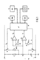
- Figure 1 shows a measuring circuit in accordance with the invention.
- a series arrangement of a first resistor 6 and a capacitor 8, which are connected to one another in a node 10, is connected between a positive supply terminal 2 and a negative supply terminal 4, which is assumed to be earthed.
- a discharge switch 12 is arranged in parallel with the capacitor 8 and can be opened and closed by means of a first switching signal S 1 .
- a series arrangement of a second resistor 14 and a parallel switch 16 is arranged in parallel with the first resistor 6. The parallel switch 16 can be opened and closed by means of a second switching signal S 2 , as a result of which the second resistor 14 is connected in parallel or is not connected in parallel with the first resistor 6.
- a first comparator 18 has one input connected to the node 10 and has another input connected to a first reference voltage source 20, which generates a first reference voltage Uref 1 .
- the first comparator 18 supplies a first detection signal D 1 , whose value changes if the capacitor voltage Uc on the node 10 passes the first reference voltage Uref 1 .
- a second comparator 22 also has one input connected to the node 10 and has another input connected to a second reference voltage source 24, which generates a second reference voltage Uref 2 .
- the second comparator 22 supplies a second detection signal D 2 , whose value changes if the capacitor voltage Uc on the node 10 passes the second reference voltage Uref 2 .
- the second reference voltage Uref 2 has a value which lies between the first reference voltage Uref 1 and the residual voltage Ucr across the capacitor 8 immediately after the capacitor 8 has discharged via the discharge switch 12.
- the detection signals D 1 and D 2 are applied to inputs of a microcontroller (also referred to as microprocessor) 26, which under control of a program stored in a ROM (read-only memory) 28 provides the timing of the measuring circuit and inter alia generates the switching signals S 1 and S 2 for controlling the discharge switch 12 and the parallel switch 16.
- a microcontroller also referred to as microprocessor
- ROM read-only memory
- the program of the microcontroller 26 has subroutines to count clock pulses (not shown) during time intervals defined by the detection signals D 1 and D 2 , subroutines to store the counts in a RAM (random-access memory) 30, subroutines to perform mathematical operations on the counts and, depending on the use of the measuring circuit, subroutines to apply results of mathematical operations to, for example, a display 32 or a digital-to-analog converter 34.
- the measuring circuit can measure the resistance value of the second resistor 14 if the resistance value of the first resistor 6 is known and vice versa.
- one of the two resistors functions as the known reference resistance and the other resistor is the unknown resistance to be measured.
- the unknown resistance is an NTC (negative temperature coefficient) resistor the measured resistance will also be a measure of the temperature of this resistor. In that case it is also preferable to arrange the NTC resistor at the position of the second resistor 14.
- the capacitor 8 is charged two times, one time via the first resistor 6 and one time via the first resistor 6 in parallel with the second resistor 14.
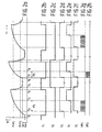
- the discharge switch 12 opens at the instant t 1 and subsequently a first measurement is effected.
- the capacitor voltage Uc at this instant is equal to the first residual voltage Ucr 1 , which is caused by the charging current through the discharge switch 12.
- the internal resistance of the discharge switch 12 is limited and can be a few hundreds of ohms in the case of transistor switches.
- the transistor switches are often incorporated in the microcontroller 26 and may exhibit a substantial spread in forward resistance.
- the capacitor voltage U c increases from the first residual voltage Ucr 1 with a first time constant ⁇ 1 , which is determined by the value R 1 of the first resistor 6 and the capacitance C of the capacitor 8 (Fig. 2 (a)).
- a first time constant ⁇ 1 which is determined by the value R 1 of the first resistor 6 and the capacitance C of the capacitor 8 (Fig. 2 (a)).
- the capacitor voltage Uc reaches the value of the second reference voltage Uref 2 and the value of the second detection signal D 2 changes (Fig. 2 (d)).
- a first clock-pulse count CNT 1 is started by the microcontroller 26.
- the capacitor voltage U c reaches the value of the first reference voltage Uref 1 and the value of the first detection signal D 1 changes (Fig. 2 (e)).
- the count CNT 1 now stops.
- the clock pulse count CNT 1 is subsequently stored in the RAM 30.
- Udd supply voltage on the positive supply terminal 2 relative to earth
- the capacitor voltage U c increases from the second residual voltage Ucr 2 with a second time constant ⁇ 2 , which is determined by the value R p of the first resistor 6 in parallel with the second resistor 14 and the capacitance C of the capacitor 8 (Fig. 2 (a)).
- a second clock-pulse count CNT 2 is started by the microcontroller 26.
- the capacitor voltage Uc reaches the first reference voltage Uref 1 and the value of the first detection signal D 1 changes again (Fig. 2 (e)).
- the count CNT 2 now stops.
- the clock pulse count CNT 2 is subsequently stored in the RAM 30.
- R 2 the resistance value of the second resistor 14
- ⁇ 2 R p *C
- R p R 1 *R 2 /(R 1 +R 2 )
- t 6 0.
- the capacitor voltage Uc then varies in accordance with a formula comparable to formula (1).
- the second resistor 14 is an NTC resistor the value thus found is compared with a table in the ROM 28 and is converted to a signal whose value is representative of the temperature of the relevant NTC resistor. If the circuit is used in an electronic thermometer this temperature signal is shown on the display 32 in a suitable manner.
- the discharging process of the capacitor 8 can be prolonged as required.
- the timing of the switching signals S 1 and S 2 can be chosen so as to ensure that the capacitor 8 is not discharged prematurely for any value of the time constant ⁇ 2 .
- the second resistor is an NTC resistor its resistance value can vary from some hundreds of kilo-ohms at low temperature to some hundreds of ohms at high temperature. Arranging the NTC resistor at the position of the second resistor 14 now ensures that the time constant for charging the capacitor 8 in the case of parallel-connected resistors is smaller than in the case that the resistors are not connected in parallel.
- the discharge switch 12 and the parallel switch 16 can be constructed as relays with relay contacts or as transistor switches.
- the discharge switch 12 is, for example, an NMOS or NPN transistor and the parallel switch 16 a PMOS or PNP transistor.
- Figure 3 shows a simplified measuring circuit.
- the first reference voltage source 20 and the second reference voltage source 24 can be replaced by a single controllable voltage source 36 whose voltage is switched via an interface circuit 38 under control of a third switching signal S 3 .
- Fig. 2 (f) shows the timing of this third switching signal S 3 .
- the capacitor voltage Uc has passed the second reference voltage Uref 2 (t 2 , t 7 ) the reference voltage is switched from Uref 2 to Uref 1 .
- Now only one comparator 40 is needed, which has one input connected to the node 10 and another input to the controllable voltage source 36.
- the second resistor 14 is arranged in parallel with the first resistor 6 during the second measurement.
- the first resistor 6 is permanently connected to the capacitor 8.
- the capacitor 8 can be charged exclusively via the second resistor 14 during the second measurement.
- the first resistor 6 is then disconnected during the second measurement.
- the parallel switch 16 then becomes a change-over switch, which connects the first resistor 6 to the capacitor 8 during the first measurement and which connects the second resistor 14 to the capacitor 8 during the second measurement.
- This configuration again enables the value of the unknown resistance to be calculated from the measured time intervals.
- Such a changeover switch instead of the parallel switch 16 can also be used in the following embodiments and examples.
- Figure 4 shows a measuring circuit which has been simplified even further.
- the controllable voltage source 36 and the interface circuit 38 are constructed with a third resistor 42 between the negative supply terminal 4 and a node 44, a fourth resistor 46 between the node 44 and the positive supply terminal 2, and a fifth resistor 48 having one end connected to the node 44, its other end being connectible to the positive supply terminal 2 or to the negative supply terminal 4 under control of the third switching signal S 3 via a changeover switch 4.
- the inputs of the comparator 40 are connected to the nodes 10 and 44.
- the comparatively low reference voltage Uref 2 is obtained by arranging the fifth resistor 48 in parallel with the third resistor 42.
- the comparatively high reference voltage Uref 1 is obtained by arranging the fifth resistor 48 in parallel with the fourth resistor 46.
- Figure 5 shows the measuring circuit used in a thermal appliance, for example a flat-iron.
- the electronic parts are mounted on a printed circuit board 52.
- the second resistor 14 is an NTC resistor in thermal contact with the soleplate 54, which is heated by an electric heating element 56.
- the second resistor 14 is connected to a terminal 58 and a terminal 60, and the electric heating element 56 is connected to a terminal 62 and a terminal 64 of the printed circuit board 52.
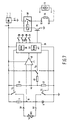
- Figure 6 is a sectional view of the iron and Figure 7 shows the circuit diagram of the printed circuit board 52.
- the temperature of the soleplate 54 can be set by means of selector switches 66 connected to input ports of the microcontroller 26.
- the electric heating element 56 is turned on and turned off by means of a relay 68, which is energised by the microcontroller 26 via a control transistor 70.
- the measured temperature of the soleplate 54 is compared with the temperature set by means of the selector switches 66. If the temperature is too low the relay 68 is energised, as a result of which the electric heating element 56 is powered from the a.c. mains and heats the soleplate 54. When the desired temperature is reached the relay is de-energised and the power supply to the electric heating element 56 is interrupted.
- the circuit shown in Figure 7 is also suitable for use in other thermal appliances having a heating element, with or without temperature control, such as coffee makers, electric kettles, deep fryers, roasters, cook-tops, ovens, grills, hot-plates, room-heating appliances, radiant heaters, fan heaters, hair dryers, hair curlers, bread toasters, sandwich toasters, electric blankets and the like.
- the circuit shown in Figure 7 can also be used in cold-generating appliances such as icemakers, food processors, refrigerators, deepfreezers, air conditioners and the like.
Landscapes
- Physics & Mathematics (AREA)
- General Physics & Mathematics (AREA)
- Engineering & Computer Science (AREA)
- Automation & Control Theory (AREA)
- Nonlinear Science (AREA)
- Measurement Of Resistance Or Impedance (AREA)
- Measuring Temperature Or Quantity Of Heat (AREA)
- Measurement Of Current Or Voltage (AREA)
- Control Of Temperature (AREA)
Abstract
Claims (10)
- Circuit de mesure pour la mesure de la valeur ohmique d'une résistance, lequel circuit comprend:un condensateur (8),une première résistance (6) et une deuxième résistance qui peuvent être couplées au condensateur (8) pour la charge du condensateur (8), tout en formant une tension de condensateur (Uc),des moyens de décharge (12) permettant de décharger le condensateur (8),une première source de tension de référence (20) permettant d'engendrer une première tension de référence (Uref1),des premiers moyens de comparaison (18) permettant de comparer la tension de condensateur (Uc) avec la première tension de référence (Uref1) et d'engendrer un premier signal de détection (D1) dans le cas où la première tension de condensateur (Uc) dépasse la première tension de référence (Uref1),des moyens de mesure de temps (26 - 30) pour la mesure d'un premier intervalle de temps qui, après décharge du condensateur (8) par les moyens de décharge (12), se termine par l'apparition du premier signal de détection (D1) pendant la charge du condensateur (8) par l'intermédiaire de la première résistance (6), et pour la mesure d'un deuxième intervalle de temps qui, après la décharge du condensateur (8) par les moyens de décharge (12), se termine par l'apparition du premier signal de détection (D1) pendant la charge du condensateur (8) par l'intermédiaire d'au moins la deuxième résistance (14), caractérisé en ce que le circuit de mesure comprend en outre:une deuxième source de tension de référence (24) pour fournir une deuxième tension de référence (Uref2) qui se situe entre la première tension de référence (Uref1) et la tension de condensateur immédiatement après la décharge du condensateur (8),des deuxièmes moyens de comparaison (22) permettant de comparer la tension de condensateur (Uc) avec la deuxième tension de référence (Uref2) et d'engendrer un deuxième signal de détection (D2) dans le cas où la tension de condensateur (Uc) dépasse la deuxième tension de référence (Uref2), et en ce quele premier intervalle de temps et le deuxième intervalle de temps commencent à l'apparition du deuxième signal de détection (D2).
- Circuit de mesure selon la revendication 1, caractérisé en ce que les premiers moyens de comparaison (18) et les deuxièmes moyens de comparaison (22) sont réunis en un seul comparateur (40), et en ce que la première source de tension de référence (20) et la deuxième source de tension de référence (24) sont réunies en une seule source de tension de référence (36), dont la tension de référence peut être commutée à partir de la deuxième tension de référence (Uref2) à la première tension de référence (Uref1) après l'apparition du deuxième signal de détection (D2).
- Circuit de mesure selon la revendication 1 ou 2, caractérisé en ce que la source de tension de référence simple (36) comprend:un diviseur de tension muni du montage en série d'une troisième résistance (42) et d'une quatrième résistance (46),une cinquième résistance (48), etdes moyens de commutation (50) permettant de connecter la cinquième résistance (48) et la troisième résistance (48) en parallèle avant l'apparition du deuxième signal de détection (D2) et de connecter la cinquième résistance (48) et la quatrième résistance (46) en parallèle après l'apparition du deuxième signal de détection (D2).
- Circuit de mesure selon la revendication 1, 2 ou 3, caractérisé en ce que la deuxième résistance (14) est constituée par une résistance dépendant de la température (CTN).
- Circuit de mesure selon la revendication 1, 2, 3 ou 4, caractérisé en ce que les moyens de décharge (12) et les moyens de commutation (16; 50) sont constitués par des transistors.
- Appareil thermique, caractérisé en ce que il comprend:un élément de chauffage électrique (56),une résistance sensible à la température (14),des moyens (26 - 30, 70, 68) pour le réglage de l'alimentation de puissance à l'élément de chauffage électrique (56) en réponse à la valeur ohmique de la résistance sensible à la température (14), etun circuit de mesure selon la revendication 1, 2, 3, 4 ou 5 dont, soit la première résistance (6), soit la deuxième résistance (14), constitue la résistance sensible à la température.
- Appareil thermique selon la revendication 6, caractérisé en ce que l'appareil thermique est un appareil du groupe comprenant: un fer à repasser, une cafétière électrique, une bouilloire, une friteuse, une plaque de cuisson, une poêle à frire, un four, une rôtissoire, un chauffe-plats, un appareil de chauffage de chambres, un radiateur électrique, un radiateur soufflant électrique, un sèche-cheveux, un fer à friser, un gril électrique, un grille-pain, une couverture électrique.
- Thermomètre électrique, caractérisé en ce qu'il comprend:une résistance sensible à la température (14),un circuit de mesure selon la revendication 1, 2, 3, 4 ou 5 dont, soit la première résistance (6), soit la deuxième résistance (14), constitue la résistance sensible à la température (14),un dispositif (26 - 30) pour fournir un signal électrique qui est représentatif de la valeur ohnique de la résistance sensible à la température (14), etun dispositif indicateur (32) pour indiquer une température en réponse au signal électrique.
- Appareil cryogène, caractérisé en ce qu'il comprend:une unité de refroidissement (72),une résistance sensible à la température (14),des moyens (26 - 30, 70, 68) pour le réglage de l'unité de refoidissement en réponse à la valeur ohmique de la résistance sensible à la température (14), etun circuit de mesure selon la revendication 1, 2, 3, 4 ou 5 dont, soit la première résistance (6), soit la deuxième résistance (14), constitue la résistance sensible à la température (14).
- Appareil cryogène selon la revendication 9, caractérisé en ce que l'appareil est constitué par un appareil du groupe comprenant: une sorbetière, un robot culinaire, un réfrigérateur, un congélateur, un conditionneur d'air.
Priority Applications (1)
| Application Number | Priority Date | Filing Date | Title |
|---|---|---|---|
| EP95911473A EP0701687B1 (fr) | 1994-04-05 | 1995-03-24 | Circuit de mesure de resistance, et appareil thermique, thermometre electrique et appareil de production de froid comportant un tel circuit |
Applications Claiming Priority (4)
| Application Number | Priority Date | Filing Date | Title |
|---|---|---|---|
| EP94200918 | 1994-04-05 | ||
| EP94200918 | 1994-04-05 | ||
| PCT/IB1995/000204 WO1995027189A1 (fr) | 1994-04-05 | 1995-03-24 | Circuit de mesure de resistance, et appareil thermique, thermometre electrique et appareil de production de froid comportant un tel circuit |
| EP95911473A EP0701687B1 (fr) | 1994-04-05 | 1995-03-24 | Circuit de mesure de resistance, et appareil thermique, thermometre electrique et appareil de production de froid comportant un tel circuit |
Publications (2)
| Publication Number | Publication Date |
|---|---|
| EP0701687A1 EP0701687A1 (fr) | 1996-03-20 |
| EP0701687B1 true EP0701687B1 (fr) | 1999-07-28 |
Family
ID=8216762
Family Applications (1)
| Application Number | Title | Priority Date | Filing Date |
|---|---|---|---|
| EP95911473A Expired - Lifetime EP0701687B1 (fr) | 1994-04-05 | 1995-03-24 | Circuit de mesure de resistance, et appareil thermique, thermometre electrique et appareil de production de froid comportant un tel circuit |
Country Status (7)
| Country | Link |
|---|---|
| US (1) | US5657238A (fr) |
| EP (1) | EP0701687B1 (fr) |
| JP (1) | JPH08511352A (fr) |
| KR (1) | KR960702903A (fr) |
| CN (1) | CN1126514A (fr) |
| DE (1) | DE69511020T2 (fr) |
| WO (1) | WO1995027189A1 (fr) |
Cited By (1)
| Publication number | Priority date | Publication date | Assignee | Title |
|---|---|---|---|---|
| CN100520319C (zh) * | 2005-08-31 | 2009-07-29 | 日本特殊陶业株式会社 | 温度传感器控制装置 |
Families Citing this family (28)
| Publication number | Priority date | Publication date | Assignee | Title |
|---|---|---|---|---|
| GB2327161B (en) * | 1997-07-10 | 2001-05-16 | Ericsson Telefon Ab L M | Timing circuit |
| US6198295B1 (en) * | 1999-01-06 | 2001-03-06 | Honeywell Inc. | Apparatus and method for detecting electrical resistance change in connectors to a remote mounted sensor |
| DE19930149B4 (de) * | 1999-06-30 | 2004-07-01 | Texas Instruments Deutschland Gmbh | Verfahren zum Messen einer elektrischen Spannung und Anordnungen zur Durchführung der Verfahren |
| CN1131436C (zh) * | 1999-09-21 | 2003-12-17 | 容云 | 一种电容、电阻、电感-数字转换电路 |
| US6824307B2 (en) * | 2000-12-12 | 2004-11-30 | Harris Corporation | Temperature sensor and related methods |
| US7413343B2 (en) * | 2005-09-16 | 2008-08-19 | Kyocera Wireless Corp. | Apparatus for determining a temperature sensing element |
| DE102007007007A1 (de) * | 2007-02-08 | 2008-08-14 | Endress + Hauser Gmbh + Co. Kg | Vorrichtung zur Bestimmung und/oder Überwachung einer Prozessgröße |
| KR100896534B1 (ko) * | 2007-07-27 | 2009-05-08 | 한국표준과학연구원 | 직접 측정방법으로 얻은 다수의 변수를 비교하여 얻은비율값으로부터 각각의 변수값을 구하는 방법 |
| JP5213175B2 (ja) * | 2008-11-14 | 2013-06-19 | セイコーインスツル株式会社 | 温度センサ |
| US8564269B2 (en) * | 2008-12-13 | 2013-10-22 | Hewlett-Packard Development Company, L.P. | Systems and methods for scaling a signal in a power factor correction circuit |
| JP5736744B2 (ja) * | 2010-01-26 | 2015-06-17 | セイコーエプソン株式会社 | 熱センサーデバイス及び電子機器 |
| KR101741083B1 (ko) | 2010-06-24 | 2017-05-29 | 삼성전자주식회사 | 염도 측정 장치 |
| CN102467091B (zh) * | 2010-11-11 | 2017-03-01 | 帝斯贝思数字信号处理和控制工程有限公司 | 具有故障仿真的电池模拟设备及方法 |
| LU91839B1 (en) * | 2011-07-08 | 2013-01-09 | Iee Sarl | Impedance measurement system |
| DE102012204569B3 (de) | 2012-03-22 | 2013-08-22 | Continental Automotive Gmbh | Vorrichtung und Verfahren zum Messen des Wertes eines Widerstands |
| US9482706B2 (en) * | 2012-12-11 | 2016-11-01 | Dust Company, Inc. | Methods and circuits for measuring a high impedance element based on time constant measurements |
| US10060959B2 (en) * | 2013-02-27 | 2018-08-28 | Texas Instruments Incorporated | Capacitive sensing |
| KR101615435B1 (ko) * | 2014-06-09 | 2016-04-26 | 한국과학기술원 | 센서 저항을 이용한 온도 측정 장치 및 그 방법 |
| ITUB20160548A1 (it) | 2016-02-08 | 2017-08-08 | St Microelectronics Srl | Interfaccia di sensore resistivo |
| DE102018200931A1 (de) * | 2018-01-22 | 2019-07-25 | Robert Bosch Gmbh | Verfahren zum Aktivieren einer Recheneinheit mittels einer Schaltungsanordnung in Reaktion auf ein Aktivierungssignal |
| CN108469393B (zh) * | 2018-02-02 | 2021-04-06 | 中山市积目科技有限公司 | 一种冷热冲击试验设备 |
| CN109188095B (zh) * | 2018-10-11 | 2024-05-17 | 深圳和而泰智能控制股份有限公司 | 一种电阻测量电路、方法及环境参数测量装置 |
| JP7303021B2 (ja) * | 2019-05-29 | 2023-07-04 | ローム株式会社 | 容量測定回路、容量測定方法、電源回路、データ記憶装置、電源管理回路 |
| US11255892B2 (en) * | 2019-06-05 | 2022-02-22 | Cirrus Logic, Inc. | Phase compensation in a resonant phase detector |
| DE102019126005B4 (de) | 2019-09-26 | 2022-08-04 | Ifm Electronic Gmbh | Taktiler Kraft-Weg-Sensor für eine Ladeklappe in einem Elektrofahrzeug |
| CN111367332B (zh) * | 2020-02-17 | 2021-03-30 | 深圳芥子科技有限公司 | 基于电阻的温度采集电路及控制方法 |
| CN111751017A (zh) * | 2020-07-03 | 2020-10-09 | 格力电器(郑州)有限公司 | 空调感温包检测电路和空调感温包检测装置 |
| DE102020212559A1 (de) * | 2020-10-05 | 2022-04-07 | Brose Fahrzeugteile SE & Co. Kommanditgesellschaft, Würzburg | Elektrische Schaltungsanordnung zur Überwachung eines Verbindungszustands eines Hochvolt-Steckverbinders mit einer Motorelektronik |
Family Cites Families (11)
| Publication number | Priority date | Publication date | Assignee | Title |
|---|---|---|---|---|
| FR2134112B1 (fr) * | 1971-04-20 | 1974-03-22 | Sodern | |
| GB1589957A (en) * | 1977-05-23 | 1981-05-20 | Fluke Mfg Co John | Method and apparatus for determining the resistance value of an unknown resistance by measuring the conductance of that resistance |
| EP0010823A1 (fr) * | 1978-11-02 | 1980-05-14 | Ahi Operations Limited | Procédés et appareil pour mesurer la conductibilité électrique |
| GB2076547A (en) * | 1980-05-16 | 1981-12-02 | Honeywell Inc | Resistance Measuring Circuit |
| DE3032091C2 (de) * | 1980-08-26 | 1986-09-04 | Elster AG, Meß- und Regeltechnik, 6700 Ludwigshafen | Vorrichtung zur elektrischen Wärmemengenmessung |
| CH665027A5 (de) * | 1984-09-06 | 1988-04-15 | Mettler Instrumente Ag | Verfahren zur messung und digitalisierung eines widerstandes und schaltung zur durchfuehrung des verfahrens. |
| US4910689A (en) * | 1986-12-25 | 1990-03-20 | Canon Kabushiki Kaisha | Resistivity value measuring circuit |
| US4841458A (en) * | 1987-07-07 | 1989-06-20 | Honeywell, Incorporated | Analog to digital conversion by measuring the ratio of RC time constants |
| JP2574318B2 (ja) * | 1987-08-28 | 1997-01-22 | 松下電器産業株式会社 | コ−ドレスアイロン |
| US4929886A (en) * | 1989-07-26 | 1990-05-29 | Hanwa Electronic Co., Ltd. | Apparatus for detecting noise in the measurement of very small resistance |
| US5274334A (en) * | 1989-12-18 | 1993-12-28 | Honeywell Inc. | Calibrated physical parameter value measurement system |
-
1995
- 1995-03-24 JP JP7525543A patent/JPH08511352A/ja active Pending
- 1995-03-24 WO PCT/IB1995/000204 patent/WO1995027189A1/fr not_active Ceased
- 1995-03-24 EP EP95911473A patent/EP0701687B1/fr not_active Expired - Lifetime
- 1995-03-24 DE DE69511020T patent/DE69511020T2/de not_active Expired - Fee Related
- 1995-03-24 CN CN95190267A patent/CN1126514A/zh active Pending
- 1995-04-05 US US08/417,181 patent/US5657238A/en not_active Expired - Fee Related
- 1995-12-05 KR KR1019950705489A patent/KR960702903A/ko not_active Withdrawn
Cited By (1)
| Publication number | Priority date | Publication date | Assignee | Title |
|---|---|---|---|---|
| CN100520319C (zh) * | 2005-08-31 | 2009-07-29 | 日本特殊陶业株式会社 | 温度传感器控制装置 |
Also Published As
| Publication number | Publication date |
|---|---|
| JPH08511352A (ja) | 1996-11-26 |
| CN1126514A (zh) | 1996-07-10 |
| DE69511020T2 (de) | 2000-02-24 |
| DE69511020D1 (de) | 1999-09-02 |
| KR960702903A (ko) | 1996-05-23 |
| US5657238A (en) | 1997-08-12 |
| WO1995027189A1 (fr) | 1995-10-12 |
| EP0701687A1 (fr) | 1996-03-20 |
Similar Documents
| Publication | Publication Date | Title |
|---|---|---|
| EP0701687B1 (fr) | Circuit de mesure de resistance, et appareil thermique, thermometre electrique et appareil de production de froid comportant un tel circuit | |
| CA1128593A (fr) | Friteuse a circuit de commande-regulation a semiconducteurs | |
| US5455887A (en) | Coffee-maker | |
| KR900002781B1 (ko) | 가열 조리기 | |
| US6060698A (en) | Method of controlling the operation of a cooking appliance | |
| US4296312A (en) | Electronic temperature sensing system for toaster appliances | |
| US6380521B1 (en) | Kitchen appliance with improved heating element control | |
| WO1997000596A1 (fr) | Four culinaire | |
| JPH0356725B2 (fr) | ||
| US4742246A (en) | Preheat timer for use in oven | |
| US2858699A (en) | Cooking temperature measuring apparatus | |
| GB1588795A (en) | Electrically heated cooking apparatus | |
| US20040144257A1 (en) | Temperature compensation in an electronic circuit toaster | |
| GB1565796A (en) | Electronic temperature sensing for toaster appliances | |
| CN113598616A (zh) | 一种烹饪设备测温控制方法及烹饪设备 | |
| US5698123A (en) | Toaster compensation for repeated use | |
| JP2585765B2 (ja) | 加熱調理器 | |
| JPS6036072B2 (ja) | 焙焼制御装置 | |
| CN116157660B (zh) | 具有核心温度传感器的温度测量设备 | |
| JPH0138403Y2 (fr) | ||
| JPS5828499B2 (ja) | ヒ−タ付電子レンジ | |
| JPS62186822A (ja) | コ−ヒ−抽出器 | |
| CN117849093A (zh) | 一种判沸检测及防溢控制电路、判沸防溢方法、家用电器 | |
| JPS6354976B2 (fr) | ||
| JPS5849250B2 (ja) | 自動煮物鍋 |
Legal Events
| Date | Code | Title | Description |
|---|---|---|---|
| PUAI | Public reference made under article 153(3) epc to a published international application that has entered the european phase |
Free format text: ORIGINAL CODE: 0009012 |
|
| AK | Designated contracting states |
Kind code of ref document: A1 Designated state(s): DE DK GB IT |
|
| 17P | Request for examination filed |
Effective date: 19960412 |
|
| GRAG | Despatch of communication of intention to grant |
Free format text: ORIGINAL CODE: EPIDOS AGRA |
|
| 17Q | First examination report despatched |
Effective date: 19981020 |
|
| GRAG | Despatch of communication of intention to grant |
Free format text: ORIGINAL CODE: EPIDOS AGRA |
|
| GRAH | Despatch of communication of intention to grant a patent |
Free format text: ORIGINAL CODE: EPIDOS IGRA |
|
| GRAG | Despatch of communication of intention to grant |
Free format text: ORIGINAL CODE: EPIDOS AGRA |
|
| GRAH | Despatch of communication of intention to grant a patent |
Free format text: ORIGINAL CODE: EPIDOS IGRA |
|
| GRAH | Despatch of communication of intention to grant a patent |
Free format text: ORIGINAL CODE: EPIDOS IGRA |
|
| GRAA | (expected) grant |
Free format text: ORIGINAL CODE: 0009210 |
|
| AK | Designated contracting states |
Kind code of ref document: B1 Designated state(s): DE DK GB IT |
|
| PG25 | Lapsed in a contracting state [announced via postgrant information from national office to epo] |
Ref country code: IT Free format text: LAPSE BECAUSE OF FAILURE TO SUBMIT A TRANSLATION OF THE DESCRIPTION OR TO PAY THE FEE WITHIN THE PRESCRIBED TIME-LIMIT;WARNING: LAPSES OF ITALIAN PATENTS WITH EFFECTIVE DATE BEFORE 2007 MAY HAVE OCCURRED AT ANY TIME BEFORE 2007. THE CORRECT EFFECTIVE DATE MAY BE DIFFERENT FROM THE ONE RECORDED. Effective date: 19990728 |
|
| REF | Corresponds to: |
Ref document number: 69511020 Country of ref document: DE Date of ref document: 19990902 |
|
| PG25 | Lapsed in a contracting state [announced via postgrant information from national office to epo] |
Ref country code: DK Free format text: LAPSE BECAUSE OF FAILURE TO SUBMIT A TRANSLATION OF THE DESCRIPTION OR TO PAY THE FEE WITHIN THE PRESCRIBED TIME-LIMIT Effective date: 19991028 |
|
| PLBE | No opposition filed within time limit |
Free format text: ORIGINAL CODE: 0009261 |
|
| STAA | Information on the status of an ep patent application or granted ep patent |
Free format text: STATUS: NO OPPOSITION FILED WITHIN TIME LIMIT |
|
| 26N | No opposition filed | ||
| PGFP | Annual fee paid to national office [announced via postgrant information from national office to epo] |
Ref country code: GB Payment date: 20010330 Year of fee payment: 7 |
|
| PGFP | Annual fee paid to national office [announced via postgrant information from national office to epo] |
Ref country code: DE Payment date: 20010516 Year of fee payment: 7 |
|
| REG | Reference to a national code |
Ref country code: GB Ref legal event code: IF02 |
|
| PG25 | Lapsed in a contracting state [announced via postgrant information from national office to epo] |
Ref country code: GB Free format text: LAPSE BECAUSE OF NON-PAYMENT OF DUE FEES Effective date: 20020324 |
|
| PG25 | Lapsed in a contracting state [announced via postgrant information from national office to epo] |
Ref country code: DE Free format text: LAPSE BECAUSE OF NON-PAYMENT OF DUE FEES Effective date: 20021001 |
|
| GBPC | Gb: european patent ceased through non-payment of renewal fee |
Effective date: 20020324 |