EP0701793A2 - Vorrichtung mit einer Lochwand und Verfahren zur Befestigung eines Aufhängers an einer Lochwand - Google Patents
Vorrichtung mit einer Lochwand und Verfahren zur Befestigung eines Aufhängers an einer Lochwand Download PDFInfo
- Publication number
- EP0701793A2 EP0701793A2 EP95630100A EP95630100A EP0701793A2 EP 0701793 A2 EP0701793 A2 EP 0701793A2 EP 95630100 A EP95630100 A EP 95630100A EP 95630100 A EP95630100 A EP 95630100A EP 0701793 A2 EP0701793 A2 EP 0701793A2
- Authority
- EP
- European Patent Office
- Prior art keywords
- pegboard
- section
- aperture
- engaging
- hanging apparatus
- Prior art date
- Legal status (The legal status is an assumption and is not a legal conclusion. Google has not performed a legal analysis and makes no representation as to the accuracy of the status listed.)
- Ceased
Links
- 238000000034 method Methods 0.000 title claims abstract description 20
- 238000011010 flushing procedure Methods 0.000 claims description 6
- 230000008878 coupling Effects 0.000 claims 1
- 238000010168 coupling process Methods 0.000 claims 1
- 238000005859 coupling reaction Methods 0.000 claims 1
- 238000013461 design Methods 0.000 description 4
- 238000006073 displacement reaction Methods 0.000 description 2
- 230000001815 facial effect Effects 0.000 description 2
- 238000009434 installation Methods 0.000 description 2
- 239000003381 stabilizer Substances 0.000 description 2
- 238000009966 trimming Methods 0.000 description 2
- 238000011835 investigation Methods 0.000 description 1
- 239000000463 material Substances 0.000 description 1
- 238000005259 measurement Methods 0.000 description 1
- 238000012986 modification Methods 0.000 description 1
- 230000004048 modification Effects 0.000 description 1
- 230000006641 stabilisation Effects 0.000 description 1
- 238000011105 stabilization Methods 0.000 description 1
- 230000000087 stabilizing effect Effects 0.000 description 1
- 238000006467 substitution reaction Methods 0.000 description 1
Images

Classifications
-
- A—HUMAN NECESSITIES
- A47—FURNITURE; DOMESTIC ARTICLES OR APPLIANCES; COFFEE MILLS; SPICE MILLS; SUCTION CLEANERS IN GENERAL
- A47F—SPECIAL FURNITURE, FITTINGS, OR ACCESSORIES FOR SHOPS, STOREHOUSES, BARS, RESTAURANTS OR THE LIKE; PAYING COUNTERS
- A47F5/00—Show stands, hangers, or shelves characterised by their constructional features
- A47F5/08—Show stands, hangers, or shelves characterised by their constructional features secured to the wall, ceiling, or the like; Wall-bracket display devices
- A47F5/0807—Display panels, grids or rods used for suspending merchandise or cards supporting articles; Movable brackets therefor
- A47F5/0815—Panel constructions with apertures for article supports, e.g. hooks
- A47F5/0823—Article supports for peg-boards
Definitions
- the present invention generally relates to a combination of a hanging apparatus combinedly engaged to a pegboard, and to a method for installing a hanging apparatus, such as a peghook, on a pegboard.
- U.S. Patent No. 2,957,671 teaches a quick releasable means for holding two or more perforate wall boards or panels firmly clamped together in face to face contact by the use of two wire staying devices having jogged ends anchored in the holes of the wall board.
- U.S. Patent No. 3,037,732 teaches stabilization of peg board hangers through the use of separately formed stabilizing means, and discloses providing such a separately formed stabilizer by means of which the lower body portion of the hanger may be positively held against forward displacement with respect to the board.
- U.S. Patent No. 3,310,271 provides an apertured board having an appearance wherein an elongated slot is employed in lieu of the customary round hole.
- a hook member having a cross member key at the end is used.
- the cross member is sized to fit in the elongated slot and to lock against the back of the apertured board when either angularly turned or otherwise moved relative to the aperture, thereby preventing the hook from falling out.
- U.S. Patent No. 4,750,700 teaches a hook apparatus used for hanging articles on peghoards which includes a length of plated, resilient wire bent a various points and at various angles to create a hook which requires only a single hole for tight engagement. Due to the geometrical configuration of the sections relative to the board surface and to the pegboard hole, pressing the hook into position in a single hole in a pegboard generates a spring force in the hook which is opposed by the pegboard surface and hole edges, and which holds the hook tightly in position.
- the hook apparatus is taught to be of such a configuration that the hook may be engaged in an upper pegboard hole for maximum tightness, with a stabilizer bend portion engaging a next lower hole to resist side-to-side deflection.
- U.S. Patent No. 5,054,728 teaches a pegboard hanger having a pair of shoulder members to pass through apertures in the pegboard with a body extending from the shoulder members in front of the pegboard and a neck member on each shoulder member disposed behind the pegboard, with such neck members extending at an outward angle to a vertical axis to retain the hanger in the pegboard.
- U.S. Patent No. 5,104,082 teaches a chandelier hook for a chandelier trimming.
- the hook is disclosed as having a pair of bends, one of which is adapted for engagement with an opening in a chandelier frame and the other of which is adapted to resist accidental displacement of the trimming from the chandelier frame.
- U.S. Design Patent No. 260,234 discloses an ornamental design for a releasable hook.
- U.S. Design Patent No. 280,596 discloses an ornamental design for a security-peg board fastener.
- the present invention accomplishes its desired objects by broadly providing a method for installing a hanging apparatus (e.g. a peghook) on a pegboard comprising the steps of:
- the upright member which preferably couples the helical body with the carrier member is generally parallel to the pegboard front and disposed essentially vertically or upright above the pegboard aperture when viewed in a front elevational view; and subsequent to the rotating step (d), the upright member is generally parallel to the pegboard front and disposed essentially vertically or upright below the pegboard aperture when viewed in the front elevational view. Subsequent to the rotating step (d) , the upright member is in close proximity to the peghoard. Also subsequent to the rotating step (d) the first and second pegboard engaging helical sections biasingly compress against a section of the pegboard immediately above the pegboard aperture. The rotating step (d) is counterclockwise relative to a front elevational view.
- the present invention also accomplishes its desired objects by broadly providing in combination a hanging apparatus and a pegboard.
- the peg board has a pegboard back and a pegboard front and a pegboard structure defining at least one pegboard aperture.
- the hanging apparatus (or peghook) is steadfastly rotatively secured to the pegboard.
- the hanging apparatus has a helical body extending into the pegboard aperture and integrally engaged or secured to a neck member and to an upright member.
- a carrier member is integrally engaged to or secured to the upright member.
- the helical body includes a first pegboard engaging helical section engaged and essentially flushed against the pegboard back and a second pegboard engaging helical section engaged and essentially flushed against the pegboard front such that the first pegboard engaging helical section and the second pegboard engaging helical section generally sandwiches (or biasingly compresses with a spring-like force) a section of the pegboard therebetween in order that the hanging apparatus becomes generally steadfastly secured to the pegboard against any upward or downward force on the carrier member.
- the biasingly compressed section of the pegboard may be at any suitable location on the pegboard, but is preferably in close proximity to the pegboard aperture, more preferably above the pegboard aperture.
- a hanging apparatus e.g. a peghook
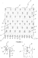
- a pegboard generally illustrated as 10 , having a plurality of apertures or pegholes 12 for receiving one or more (i.e. at least one) peghooks (or hanging apparatus), generally illustrated as 14 .
- the pegboard 10 has a back (surface) 16 and a front (surface) 18 .
- the peghooks 14 have various embodiments.
- the peghook 14 (or hanging apparatus) has a spiral or helical body, generally illustrated as 20 .
- the helical body 20 opposedly terminates in a neck member 22 and is coupled to a carrier member 26 , preferably via a generally upright member 24 .
- the neck member 22 and the upright member 24 are integrally secured to the helical body 20 in an opposed relationship.
- the neck member 22 defines an angled tip or a protruding stub end.
- a carrier member 26 for carrying or holding or hanging any article (e.g.
- screw drivers, pliers, bags, display cards, various assembly tools or other assembly articles in commerce, etc. for any use is coupled to the upright member 24 , preferably by being integrally engaged to or connected to the upright member 24 which in turn is integrally secured to the helical body 20 .
- the helical body 20 has a pair of general helical sections 30 and 32 which terminate in each other.
- the general helical sections 30 and 32 are continuous in each other such that a dividing point 80 (see Fig. 8) from and/or between the two helical sections 30 and 32 is generally approximate.
- Helical section 30 is for engaging and generally flushing against the back 16 of the pegboard 10 .
- helical section 30 is engaged against and/or is essentially flushed against the back 16 .
- helical section 30 is for engaging and generally flushing against the back 16 of the pegboard.
- helical section 32 is engaged against and/or is essentially flushed against the front 18 .
- helical section 30 and helical section 32 sandwich (or slightly compress) together a section 50 of the pegboard 10 immediately above the aperture 12 wherein and partly wherethrough the helical body 20 passes. Stated alternatively, the helical body 20 passes into one of the apertures 12 such that helical section 30 (due to the spring like or resilient like material (e.g.
- helical section 32 biasingly, compressingly engages the front (which is part of the front 18 of the pegboard 10 ) of section 50 . Because helical sections 30 and 32 are spaced apart (see fig.
- the hanging apparatus or peghook 14 in such a degree and/or at a measurement, which is slightly less than the thickness of the section 50 of the pegboard 10 , such a biasingly, compressingly arrangement is possible; and the biasingly, compressingly arrangement enables the hanging apparatus or peghook 14 to be generally steadfastly or generally fixedly secured to the pegboard 10 (more particularly to section 50 of the pegboard 10 ) against any upward force (more specifically against any upward arcuate moving force as generally represented by arrow A in Fig. 8) or any downward force (more specifically against any downward arcuate moving force as generally represented by arrow B in Fig. 8) on the carrier member 26 .
- the stated peghook 14 may not be moved upwardly or downwardly to produce a loosely fitting peghook 14 that easily falls off of the pegboard 10 , it may be rotated in a desired direction, such as clockwise in Figs. 8 and 9 for removing the stated peghook 14 from the stated or helical-body-receiving aperture 12 .
- a desired direction such as clockwise in Figs. 8 and 9 for removing the stated peghook 14 from the stated or helical-body-receiving aperture 12 .
- the upright member 24 of the peghook 14 is proximity to the pegboard 10 , more specifically in close proximity to a section 60 of the pegboard 10 below (preferably immediately below) the above-stated aperture 12 .
- close proximity it is to be understood and interpreted broadly such as to have the upright member 24 not necessarily touching but postured immediately off or away from the surface 60 of the front 18 , preferably postured immediately off or away from the surface 60 of the front 18 such that if the carrier member 26 is weighted with an article, the upright member 24 is capable of engaging the front 18 , more particularly section 60 of the pegboard 10 , to further assist helical section 30 and 32 of the helical body 20 in maintaining the peghook 14 essentially steadfastly and/or fixedly secured to the pegboard 10 , especially against any upwardly or downwardly movement or force (particularly on or against the carrier member 26 ) for loosening the peghook 14 within the above-stated particular aperture 12 which could cause the subject peghook 14 to fall off of the pegboard 10 .
- close proximity it is to also be understood and is to be broadly interpreted such as to have the upright member 24 also or essentially flushed and/or engaged to or against the front 18 which is preferably proximately located to the above-stated aperture 12 , more preferably located immediately below the above-stated aperture 12 and opposed (i.e. diametrically opposed) relative to the section 50 with respect to the above-stated aperture 12 .
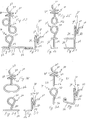
- the peghook 14 has various preferred embodiments.
- the feature that distinguishes each preferred embodiment over the remaining preferred embodiments is the various embodiments of the carrier member 26 .
- the carrier member 26 is formed by or with an arcuate-like structure.
- the carrier member 26 consists of a pair of spaced circular-like structures.
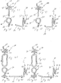
- the carrier member 26 for the preferred embodiment of the peghook in Figs. 19 - 21 and Figs. 28 - 30 consist of a single circular-like or generally elliptical structure.
- the carrier member 26 is seen to be a figure 8-like structure.
- the carrier member 26 is seen to be either acutely angularly disposed relative to the upright member 24 or (as seen in Figs. 31 - 33) terminating in an askewed structure, or (as shown in Figs. 37 - 39) generally normally postured with respect to the upright member 24 and terminating in an upwardly angled tip-like structure.
- the carrier member 26 possesses an elongated-like opening, with the elongated-like opening being deformed and skewed or bent upwardly as shown in Figs. 43 - 45.
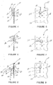
- any one of the various embodiments of the peghook 14 is grasped and held suspendidly such that the neck member 22 is generally aligned with one of the apertures 12 as best shown in Fig. 2.
- the associated neck member 22 of the pegboard 14 is inserted into the aperture 12 (see Fig. 4).
- the associated upright member 24 is generally parallel to the facial plane of the front 18 of the pegboard 10 and is essentially upright or vertically above the neck-received aperture 12 when viewed in a front elevational view, such as the front elevational view in Fig. 5.
- the stated peghook 14 is subsequently rotated (i.e. a counterclockwise rotation) about 180° degrees for passing (rotatably) the helical section 30 through the stated aperture 12 (see Figs. 6 - 9).
- the approximate 180° degree rotation may be done in two (2) stages such as an initial approximate 90° degree rotation as best shown in Figs.
- the approximate 180° degree rotation causes the helical section 30 to become engaged and essentially flushed against the pegboard back 16 (more specifically against the back of section 50 ), and further causes the helical section 32 to become engaged and essentially flushed against the pegboard front 18 (more specifically against the front of the section 50 ) such that the stated pegboard 14 becomes steadfastly rotatably secured to the pegboard 10 , especially against any upward or downward force on the carrier member 26 .
- the associated upright member 24 is generally parallel to the facial plane of the front 18 of the pegboard 10 and is essentially upright or vertically below the addressed and stated aperture 12 when viewed in a front elevational view, such as the front elevational view in Fig. 9.
- the approximate dividing point 80 is situated in or circumscribed by the stated aperture 12 as best shown in Fig. 8. If the stated peghook 14 is to be removed the procedure is reversed; more specifically , the stated peghook 14 is rotatively reversed about 180° degrees in a direction opposite to the installation direction, such as clockwise with respect to the front elevational view in Fig. 9.
- the approximate 180° degree opposite rotational (clockwise) direction causes the helical section 30 to move out from behind the pegboard 10 and pass through the stated aperture 12 for the subsequent withdrawal of the neck 22 out of the same stated aperture.
Landscapes
- Holders For Apparel And Elements Relating To Apparel (AREA)
- Medicinal Preparation (AREA)
- External Artificial Organs (AREA)
- Replacement Of Web Rolls (AREA)
- Supports Or Holders For Household Use (AREA)
- Hooks, Suction Cups, And Attachment By Adhesive Means (AREA)
Applications Claiming Priority (2)
| Application Number | Priority Date | Filing Date | Title |
|---|---|---|---|
| US08/305,827 US5490650A (en) | 1994-09-14 | 1994-09-14 | Combined hanging apparatus and pegboard and method for installing a hanging apparatus on a pegboard |
| US305827 | 1994-09-14 |
Publications (2)
| Publication Number | Publication Date |
|---|---|
| EP0701793A2 true EP0701793A2 (de) | 1996-03-20 |
| EP0701793A3 EP0701793A3 (de) | 1998-01-07 |
Family
ID=23182533
Family Applications (1)
| Application Number | Title | Priority Date | Filing Date |
|---|---|---|---|
| EP95630100A Ceased EP0701793A3 (de) | 1994-09-14 | 1995-09-14 | Vorrichtung mit einer Lochwand und Verfahren zur Befestigung eines Aufhängers an einer Lochwand |
Country Status (5)
| Country | Link |
|---|---|
| US (1) | US5490650A (de) |
| EP (1) | EP0701793A3 (de) |
| CN (1) | CN1136629A (de) |
| CA (1) | CA2158220A1 (de) |
| TW (1) | TW284834B (de) |
Families Citing this family (37)
| Publication number | Priority date | Publication date | Assignee | Title |
|---|---|---|---|---|
| US7056266B2 (en) * | 2001-09-06 | 2006-06-06 | Everlast Climbing Industries, Inc. | Climbing wall assembly |
| US20050218284A1 (en) * | 2004-04-05 | 2005-10-06 | Kurrasch David B | Monkey hook, a singl, "self-locking" metal picture hook |
| US7175147B1 (en) * | 2004-04-26 | 2007-02-13 | Matthew Marks | Stopper holder for beverage bottle |
| USD561011S1 (en) * | 2005-12-13 | 2008-02-05 | Master Lock Company Llc | Hook |
| US20070290111A1 (en) * | 2006-06-14 | 2007-12-20 | Ricardo Alonso | Non-symmetrical wire clip for clotheslines |
| US20080099155A1 (en) * | 2006-10-05 | 2008-05-01 | May Louis P | Awning strap tie down component |
| US9138078B2 (en) * | 2009-04-15 | 2015-09-22 | Southern Imperial, Inc. | Retail merchandise hanger with mounting clip |
| US8522986B2 (en) * | 2009-09-29 | 2013-09-03 | Michael Kitchen | Locking pegboard |
| USD629290S1 (en) | 2010-06-03 | 2010-12-21 | Master Lock Company Llc | Hook |
| USD628877S1 (en) | 2010-06-03 | 2010-12-14 | Master Lock Company Llc | Hook |
| USD633371S1 (en) | 2010-06-03 | 2011-03-01 | Master Lock Company Llc | Hook |
| US20120199714A1 (en) * | 2011-02-03 | 2012-08-09 | John Joseph Rinaldo | Pot rack hook |
| USD699556S1 (en) | 2012-06-11 | 2014-02-18 | Box T Brand, Llc | Fence clip |
| USD706617S1 (en) | 2012-06-11 | 2014-06-10 | Box T Brand, Llc | Fence clip |
| GB2504062A (en) * | 2012-06-12 | 2014-01-22 | Clifford Mark Burgin | Spiral device for catching and retaining a cable |
| USD672228S1 (en) * | 2012-09-10 | 2012-12-11 | Hendricks Richard L | Fence clip |
| USD672227S1 (en) * | 2012-09-10 | 2012-12-11 | Hendricks Richard L | Fence clip |
| USD673031S1 (en) * | 2012-09-10 | 2012-12-25 | Hendricks Richard L | Fence clip |
| USD687291S1 (en) * | 2013-02-20 | 2013-08-06 | Box T Brand, Llc | Fence clip |
| US20140339389A1 (en) * | 2013-05-16 | 2014-11-20 | Megan Futrell | Method, device, and system for hanging an item |
| USD741160S1 (en) * | 2014-01-06 | 2015-10-20 | Box T Brand, Llc | Fence clip |
| US9756966B2 (en) | 2015-08-05 | 2017-09-12 | Roy Kenneth Weltmeyer | Apparatus and method for horizontal storage and display of shoes |
| USD840715S1 (en) | 2016-05-12 | 2019-02-19 | Inter Ikea Systems Bv | Pegboard with attachments |
| CN206368878U (zh) * | 2016-12-27 | 2017-08-01 | 管名豪 | 一种快装定位扣 |
| CN107914613B (zh) * | 2017-12-19 | 2024-01-26 | 俱进汽车部件集团有限公司 | 一种后排座椅 |
| DE102019108615A1 (de) * | 2019-04-02 | 2020-10-08 | Michael Ulbricht | Schmuckbrett |
| US11320024B2 (en) * | 2019-06-26 | 2022-05-03 | Nite Ize, Inc. | Systems and methods for a rope, flat-strap, and bungee securing device |
| US11078986B2 (en) * | 2019-06-26 | 2021-08-03 | Nite Ize, Inc. | Systems and methods for a rope, flat-strap, and bungee securing device |
| USD980645S1 (en) * | 2019-08-08 | 2023-03-14 | Trinity International Industries, L.L.C. | Pegboard |
| USD944167S1 (en) * | 2019-09-20 | 2022-02-22 | Canoo Technologies Inc. | In-vehicle accessory attachment board |
| CN111956041A (zh) * | 2020-09-24 | 2020-11-20 | 上海梓楼科技有限公司 | 一种挂钩组件及其组合而成的挂钩架 |
| US11953129B2 (en) * | 2021-03-11 | 2024-04-09 | Affordable Wire Management, Llc | Wire positioning device |
| CA3161365C (en) * | 2021-06-02 | 2026-04-14 | BuiltRight Industries LLC | System for attaching a storage panel to a vehicle seat |
| USD1076651S1 (en) * | 2023-03-31 | 2025-05-27 | Donna Ercolano | Ornament hook |
| USD1101856S1 (en) * | 2023-09-12 | 2025-11-11 | Hangzhou Great Star Industrial Co., Ltd. | Peg board |
| US12331861B2 (en) * | 2023-10-10 | 2025-06-17 | Panduit Corp. | Cable bundle hanger with pivot joint |
| US20260020539A1 (en) * | 2024-07-17 | 2026-01-22 | Tyler Phillips | Two-way clip for hanging animal feeders |
Citations (8)
| Publication number | Priority date | Publication date | Assignee | Title |
|---|---|---|---|---|
| US260234A (en) | 1882-06-27 | Reversible ironing board or table | ||
| US280596A (en) | 1883-07-03 | Lifter for cooking utensils | ||
| US2957671A (en) | 1959-09-30 | 1960-10-25 | Joseph A A Messier | Bent wire staying devices for article support |
| US3037732A (en) | 1960-06-20 | 1962-06-05 | Donald B Roman | Stabilizing of peg board hangers |
| US3310271A (en) | 1965-10-15 | 1967-03-21 | Leonard H King | Apertured display board and hardware therefor |
| US4750700A (en) | 1987-02-26 | 1988-06-14 | Wade Earl R | Apparatus used to hang articles on boards |
| US5054728A (en) | 1990-09-12 | 1991-10-08 | Nigro Jr Philip | Pegboard hanger |
| US5104082A (en) | 1990-06-18 | 1992-04-14 | A. Schonbek & Co., Inc. | Hook for chandelier ornaments |
Family Cites Families (9)
| Publication number | Priority date | Publication date | Assignee | Title |
|---|---|---|---|---|
| US1365508A (en) * | 1920-04-21 | 1921-01-11 | Kucewicz John | Screw |
| US2208152A (en) * | 1939-05-25 | 1940-07-16 | Walter R Badhorn | Hanger |
| GB736628A (en) * | 1953-04-27 | 1955-09-14 | Sidney Abthur James Grimes | Improved means for holding articles on the face of a display stand or board |
| US3226072A (en) * | 1964-12-14 | 1965-12-28 | Bertil E Johnson | Adjustable support element |
| US3335991A (en) * | 1965-07-06 | 1967-08-15 | Epple Inc As | Combination support and lid lifter device |
| GB1230757A (de) * | 1967-01-30 | 1971-05-05 | ||
| USD260234S (en) | 1979-08-23 | 1981-08-18 | C. Sherman Johnson Co., Inc. | Releasable hook |
| GB2103073B (en) * | 1981-08-04 | 1985-01-09 | Brian John Beech | Assemblies for supporting articles |
| USD280596S (en) | 1982-11-01 | 1985-09-17 | Keeler John N | Security peg board fastener |
-
1994
- 1994-09-14 US US08/305,827 patent/US5490650A/en not_active Expired - Fee Related
-
1995
- 1995-05-08 TW TW084104540A patent/TW284834B/zh active
- 1995-09-13 CA CA002158220A patent/CA2158220A1/en not_active Abandoned
- 1995-09-13 CN CN95116942A patent/CN1136629A/zh active Pending
- 1995-09-14 EP EP95630100A patent/EP0701793A3/de not_active Ceased
Patent Citations (8)
| Publication number | Priority date | Publication date | Assignee | Title |
|---|---|---|---|---|
| US260234A (en) | 1882-06-27 | Reversible ironing board or table | ||
| US280596A (en) | 1883-07-03 | Lifter for cooking utensils | ||
| US2957671A (en) | 1959-09-30 | 1960-10-25 | Joseph A A Messier | Bent wire staying devices for article support |
| US3037732A (en) | 1960-06-20 | 1962-06-05 | Donald B Roman | Stabilizing of peg board hangers |
| US3310271A (en) | 1965-10-15 | 1967-03-21 | Leonard H King | Apertured display board and hardware therefor |
| US4750700A (en) | 1987-02-26 | 1988-06-14 | Wade Earl R | Apparatus used to hang articles on boards |
| US5104082A (en) | 1990-06-18 | 1992-04-14 | A. Schonbek & Co., Inc. | Hook for chandelier ornaments |
| US5054728A (en) | 1990-09-12 | 1991-10-08 | Nigro Jr Philip | Pegboard hanger |
Also Published As
| Publication number | Publication date |
|---|---|
| EP0701793A3 (de) | 1998-01-07 |
| CN1136629A (zh) | 1996-11-27 |
| TW284834B (de) | 1996-09-01 |
| CA2158220A1 (en) | 1996-03-15 |
| US5490650A (en) | 1996-02-13 |
Similar Documents
| Publication | Publication Date | Title |
|---|---|---|
| US5490650A (en) | Combined hanging apparatus and pegboard and method for installing a hanging apparatus on a pegboard | |
| US4405110A (en) | Fixture for perforated board | |
| US5463974A (en) | Mount for a flag, display and the like | |
| US6439520B1 (en) | Photo frame | |
| AU2003200389B2 (en) | Christmas light clip | |
| US6371427B1 (en) | Wall mounted hanger | |
| US6036149A (en) | Hanger for gypsum board by compression | |
| US20090065657A1 (en) | Hanger for fire sprinkler pipe | |
| TW580540B (en) | Mounting body for attachment to bolt body and nut body | |
| JPH0221018A (ja) | 発泡ボード等の物品の吊下げ装置 | |
| US4750700A (en) | Apparatus used to hang articles on boards | |
| US5791625A (en) | Adjustable bracket for sawtooth picture hanger | |
| US20020171017A1 (en) | Wall tack | |
| EP0808251A1 (de) | Schnappbefestigung für sonnenblende und elektrische verbinder für sonnenblendbefestigungen | |
| US5255627A (en) | Flag and flagpole attachment | |
| JP2000049516A (ja) | 中間支持装置 | |
| US5832679A (en) | Apparatus for bracing a structural component against sway and seismic disturbances | |
| US6155010A (en) | Window grill clips | |
| CA2060059C (en) | Angled connection of suspended ceiling tees | |
| US4078754A (en) | Fence post sign holder | |
| US5829731A (en) | Folding holder for flagpole | |
| US10362837B1 (en) | Closure apparatus | |
| US4863136A (en) | Picture hanger and fastener | |
| US4899990A (en) | Fence-tie | |
| US20020104945A1 (en) | Microphone holder instrument, and support plate for supporting at least a pair of microphone holder instruments |
Legal Events
| Date | Code | Title | Description |
|---|---|---|---|
| PUAI | Public reference made under article 153(3) epc to a published international application that has entered the european phase |
Free format text: ORIGINAL CODE: 0009012 |
|
| AK | Designated contracting states |
Kind code of ref document: A2 Designated state(s): BE DE ES FR GB IT |
|
| PUAL | Search report despatched |
Free format text: ORIGINAL CODE: 0009013 |
|
| AK | Designated contracting states |
Kind code of ref document: A3 Designated state(s): BE DE ES FR GB IT |
|
| 17P | Request for examination filed |
Effective date: 19980630 |
|
| GRAG | Despatch of communication of intention to grant |
Free format text: ORIGINAL CODE: EPIDOS AGRA |
|
| 17Q | First examination report despatched |
Effective date: 19990924 |
|
| STAA | Information on the status of an ep patent application or granted ep patent |
Free format text: STATUS: THE APPLICATION HAS BEEN REFUSED |
|
| 18R | Application refused |
Effective date: 20000313 |