EP0701825A1 - Appareil de liposuccion à mouvement assisté et ensemble de canule pour cet appareil - Google Patents
Appareil de liposuccion à mouvement assisté et ensemble de canule pour cet appareil Download PDFInfo
- Publication number
- EP0701825A1 EP0701825A1 EP94306845A EP94306845A EP0701825A1 EP 0701825 A1 EP0701825 A1 EP 0701825A1 EP 94306845 A EP94306845 A EP 94306845A EP 94306845 A EP94306845 A EP 94306845A EP 0701825 A1 EP0701825 A1 EP 0701825A1
- Authority
- EP
- European Patent Office
- Prior art keywords
- cannula
- hollow
- hand
- proximal end
- holdable housing
- Prior art date
- Legal status (The legal status is an assumption and is not a legal conclusion. Google has not performed a legal analysis and makes no representation as to the accuracy of the status listed.)
- Granted
Links
- 238000007443 liposuction Methods 0.000 title claims abstract description 97
- 241001631457 Cannula Species 0.000 claims abstract description 64
- 230000033001 locomotion Effects 0.000 claims description 45
- 230000014759 maintenance of location Effects 0.000 claims description 13
- 230000000717 retained effect Effects 0.000 claims description 6
- 238000000034 method Methods 0.000 abstract description 30
- 238000006073 displacement reaction Methods 0.000 abstract description 20
- 230000007246 mechanism Effects 0.000 abstract description 15
- 230000000737 periodic effect Effects 0.000 abstract description 9
- 230000001954 sterilising effect Effects 0.000 abstract description 6
- 238000004659 sterilization and disinfection Methods 0.000 abstract description 6
- 238000004140 cleaning Methods 0.000 abstract description 5
- 210000000577 adipose tissue Anatomy 0.000 description 16
- 238000007373 indentation Methods 0.000 description 11
- 238000004891 communication Methods 0.000 description 6
- 238000003780 insertion Methods 0.000 description 6
- 230000037431 insertion Effects 0.000 description 6
- 238000002316 cosmetic surgery Methods 0.000 description 5
- 238000010276 construction Methods 0.000 description 4
- 239000012530 fluid Substances 0.000 description 4
- 239000004033 plastic Substances 0.000 description 4
- CWYNVVGOOAEACU-UHFFFAOYSA-N Fe2+ Chemical compound [Fe+2] CWYNVVGOOAEACU-UHFFFAOYSA-N 0.000 description 3
- 230000008901 benefit Effects 0.000 description 3
- 239000000463 material Substances 0.000 description 3
- 206010033675 panniculitis Diseases 0.000 description 3
- 230000002093 peripheral effect Effects 0.000 description 3
- 210000004304 subcutaneous tissue Anatomy 0.000 description 3
- 238000013022 venting Methods 0.000 description 3
- 230000000712 assembly Effects 0.000 description 2
- 238000000429 assembly Methods 0.000 description 2
- 238000005520 cutting process Methods 0.000 description 2
- 230000000694 effects Effects 0.000 description 2
- 201000000079 gynecomastia Diseases 0.000 description 2
- 230000005291 magnetic effect Effects 0.000 description 2
- 238000012986 modification Methods 0.000 description 2
- 230000004048 modification Effects 0.000 description 2
- 230000008569 process Effects 0.000 description 2
- 230000009467 reduction Effects 0.000 description 2
- 238000009751 slip forming Methods 0.000 description 2
- 210000004872 soft tissue Anatomy 0.000 description 2
- 229910001220 stainless steel Inorganic materials 0.000 description 2
- 239000010935 stainless steel Substances 0.000 description 2
- 210000003813 thumb Anatomy 0.000 description 2
- 210000001519 tissue Anatomy 0.000 description 2
- 229920006362 Teflon® Polymers 0.000 description 1
- 210000001015 abdomen Anatomy 0.000 description 1
- 210000001789 adipocyte Anatomy 0.000 description 1
- 230000033228 biological regulation Effects 0.000 description 1
- 210000004204 blood vessel Anatomy 0.000 description 1
- 239000011248 coating agent Substances 0.000 description 1
- 238000000576 coating method Methods 0.000 description 1
- 230000003247 decreasing effect Effects 0.000 description 1
- 238000002224 dissection Methods 0.000 description 1
- 230000005611 electricity Effects 0.000 description 1
- 210000003414 extremity Anatomy 0.000 description 1
- 230000001815 facial effect Effects 0.000 description 1
- 230000005294 ferromagnetic effect Effects 0.000 description 1
- 239000003302 ferromagnetic material Substances 0.000 description 1
- -1 for example Substances 0.000 description 1
- 238000001746 injection moulding Methods 0.000 description 1
- 208000014674 injury Diseases 0.000 description 1
- 230000004130 lipolysis Effects 0.000 description 1
- 238000012423 maintenance Methods 0.000 description 1
- 238000004519 manufacturing process Methods 0.000 description 1
- 239000002184 metal Substances 0.000 description 1
- 230000003387 muscular Effects 0.000 description 1
- 210000001640 nerve ending Anatomy 0.000 description 1
- 230000001737 promoting effect Effects 0.000 description 1
- 238000007920 subcutaneous administration Methods 0.000 description 1
- 238000001356 surgical procedure Methods 0.000 description 1
- 230000008733 trauma Effects 0.000 description 1
Images





Classifications
-
- A—HUMAN NECESSITIES
- A61—MEDICAL OR VETERINARY SCIENCE; HYGIENE
- A61B—DIAGNOSIS; SURGERY; IDENTIFICATION
- A61B17/00—Surgical instruments, devices or methods
- A61B17/32—Surgical cutting instruments
- A61B17/320016—Endoscopic cutting instruments, e.g. arthroscopes, resectoscopes
- A61B17/32002—Endoscopic cutting instruments, e.g. arthroscopes, resectoscopes with continuously rotating, oscillating or reciprocating cutting instruments
-
- A—HUMAN NECESSITIES
- A61—MEDICAL OR VETERINARY SCIENCE; HYGIENE
- A61M—DEVICES FOR INTRODUCING MEDIA INTO, OR ONTO, THE BODY; DEVICES FOR TRANSDUCING BODY MEDIA OR FOR TAKING MEDIA FROM THE BODY; DEVICES FOR PRODUCING OR ENDING SLEEP OR STUPOR
- A61M1/00—Suction or pumping devices for medical purposes; Devices for carrying-off, for treatment of, or for carrying-over, body-liquids; Drainage systems
- A61M1/84—Drainage tubes; Aspiration tips
-
- A—HUMAN NECESSITIES
- A61—MEDICAL OR VETERINARY SCIENCE; HYGIENE
- A61M—DEVICES FOR INTRODUCING MEDIA INTO, OR ONTO, THE BODY; DEVICES FOR TRANSDUCING BODY MEDIA OR FOR TAKING MEDIA FROM THE BODY; DEVICES FOR PRODUCING OR ENDING SLEEP OR STUPOR
- A61M2202/00—Special media to be introduced, removed or treated
- A61M2202/08—Lipoids
-
- A—HUMAN NECESSITIES
- A61—MEDICAL OR VETERINARY SCIENCE; HYGIENE
- A61M—DEVICES FOR INTRODUCING MEDIA INTO, OR ONTO, THE BODY; DEVICES FOR TRANSDUCING BODY MEDIA OR FOR TAKING MEDIA FROM THE BODY; DEVICES FOR PRODUCING OR ENDING SLEEP OR STUPOR
- A61M2205/00—General characteristics of the apparatus
- A61M2205/10—General characteristics of the apparatus with powered movement mechanisms
- A61M2205/106—General characteristics of the apparatus with powered movement mechanisms reciprocating
-
- Y—GENERAL TAGGING OF NEW TECHNOLOGICAL DEVELOPMENTS; GENERAL TAGGING OF CROSS-SECTIONAL TECHNOLOGIES SPANNING OVER SEVERAL SECTIONS OF THE IPC; TECHNICAL SUBJECTS COVERED BY FORMER USPC CROSS-REFERENCE ART COLLECTIONS [XRACs] AND DIGESTS
- Y10—TECHNICAL SUBJECTS COVERED BY FORMER USPC
- Y10S—TECHNICAL SUBJECTS COVERED BY FORMER USPC CROSS-REFERENCE ART COLLECTIONS [XRACs] AND DIGESTS
- Y10S604/00—Surgery
- Y10S604/902—Suction wands
Definitions
- the present invention relates generally to a method and apparatus for performing liposuction, and more particularly to a method and apparatus for performing liposuction in a mechanically assisted manner using powered expedients.
- Suction lipectomy commonly known as liposuction or lipoxheresis
- liposuction or lipoxheresis is a well known surgical procedure used for sculpturing or contouring the human body to increase the attractiveness of its form.
- the procedure involves the use of a special type of curet known as a cannula, which is operably connected to a vacuum source.
- the cannula is inserted within a region of fatty tissue where removal thereof is desired, and the vacuum source suctions the fatty tissue through the suction aperture in the cannula and carries the aspirated fat away. Removal of fat cells by liposuction creates a desired contour that will retain its form.
- the result is a multitude of concomitant sinuses formed below the subcutaneous fatty tissue, leaving intact as far as possible the connections between the skin and underlying tissue, thereby retaining the blood vessels, the lymphatics and the nerve endings.
- the second method is the original liposuction procedure proposed by U.K. Kesselring, described in "Body Contouring with Suction Lipectomy", in Vol. 11, No. 3, July 1984, Clinics in Plastic Surgery. According to the technique, an entire layer of regular, deep fat is removed by aspiration through the cannula, leaving a smooth, deep surface of the residual panniculus. The space thus created is then compressed, optimally followed by skin retraction.
- a cannula is used in conjunction with an outer guide sheath through which the cannula can slidably pass while held in place by the handle portion of the guide sheath.
- the guided cannula While the use of this liposuction technique offers some advantages over the conventional unguided liposuction cannulas, the guided cannula nevertheless suffers from several significant shortcomings and drawbacks.
- the guided cannula requires manually thrusting the cannula through the guide sleeve repeatedly for each tunnel. Although this is a less physically demanding procedure, the surgeon must thrust the cannula even more times through each tunnel to achieve the desired effect and hence is still easily fatigued and prevented him from performing, for some time thereafter, delicate operations involved in ordinary plastic surgery.
- U.S. Patent Nos. 4,735,605, 4,775,365 and 4,792,327 to Swartz disclose an assisted lipectomy cannula having an aspiration aperture which effectively travels along a portion of the length of the cannula, thereby obviating the necessity of the surgeon to repeatedly push the cannula in and out of the patients' subcutaneous tissue where fatty tissue is to be removed. While this assisted lipectomy cannula can operate on either air or electric power, it nevertheless suffers from several significant shortcomings and drawbacks.
- the device requires an outer tube with an elongated slot and a inner tube having a spiral slot which must be rotated inside the outer tube to effectuate a traveling aspiration aperture.
- use with a variety of cannulas and highly effective fat aspiration does not appear possible.
- fat and other subcutaneous tissue such as but not restricted to gynecomastia
- An even further object of the present invention is to provide such a liposuction instrument which can be driven by air or electricity.
- a further object of the present invention is to provide such a liposuction instrument, in which the cannula assembly can be simply detached from the hand-holdable housing for ease of replacement and/or sterilization.
- An even further object of the present invention is to provide an improved method of performing liposuction, in which one of the cannulas of the cannula assembly is automatically reciprocated back and forth relative to the hand-holdable housing, to permit increased control over the area of subcutaneous tissue where fatty and other soft tissue is to be aspirated.
- the apparatus for performing power-assisted liposuction.
- the apparatus is realized as a device comprising a hand-holdable housing, a cannula assembly, and a reciprocation means.
- the hand-holdable housing has a cavity adapted for receipt of a portion of the cannula assembly.
- the cannula assembly includes a hollow inner cannula and a hollow outer cannula.
- the hollow inner cannula has a distal end and a proximal end and at least one aspiration aperture disposed about the inner cannula distal end.
- the inner cannula proximal end includes an outlet port and a continuous passageway which communicates the inner aspiration aperture with the outlet port.
- a hollow outer cannula has a distal end and a proximal end and at least one outer suction aperture disposed about the outer cannula distal end.
- the hollow inner cannula is positionable within at least a portion of the hollow outer cannula so as to enable sliding movement between the hollow outer and inner cannulas while permitting aspiration through the outer and inner suction apertures, along said continuous passageway and out of the outlet port.
- the reciprocation means is disposed within the hand-holdable housing and is operably associated with either the hollow inner cannula or the hollow outer cannula, and the other of the inner and outer cannulas is essentially stationary with respect to the hand-holdable housing.
- the inner cannula is stationarily disposed relative to the hand-holdable housing, and the outer cannula is operably associated with the reciprocation means to be selectively reciprocatable relative to the statuary inner cannula.
- the outer cannula is stationarily disposed relative to the hand-holdable housing, and the inner cannula is operably associated with the reciprocation means to be selectively reciprocatable relative to the stationary outer cannula.
- the effective aspiration aperture is periodically displaced along the distal end of cannula assembly.
- reciprocation of one of the cannulas is such that periodic displacement of the effective aspiration aperture of the cannula assembly is on the order of the length of tunnels formed in fatty tissue during the liposuction procedure.
- a number of constructions are disclosed.
- one class of power-assisted liposuction devices according to the present invention is characterized by the placement of the cannula cavity within the hand-holdable housing so that the cannula cavity extends along the longitudinal extent of the hand-holdable housing.
- the cannula cavity advantageously extends along the entire longitudinal extent of the liposuction device housing.
- the cannula assembly is releasably detachable from the hand-holdable housing to facilitate cleaning and sterilization of the liposuction device.
- the reciprocation means is realized using a gas driven piston-type motor which causes the cannula to reciprocate relative to the hand-holdable housing and means are provided for controlling the amount of aspiration aperture excursion, as well as rate of aspiration aperture reciprocation.
- a pair of gas-driven piston-type motors are used to realize the reciprocation means.
- a mechanically-operated gas flow control device is provided for automatically controlling the flow of gas to effectuate reciprocation of the aspiration aperture.
- the hand-holdable housing is realized in the form of a pistol, having a barrel portion and a handle portion, facilitating the use of a rotary type motor without compromising desired amounts of aspiration aperture excursion.
- aspiration of fat and other soft tissue can be achieved with a lightweight, hand-holdable instrument, that eliminates fatigue of the surgeon.
- the simplified mechanical construction of the instruments of the present invention provides improved performance and simplified cleaning, sterilization, and maintenance.
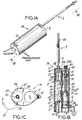
- liposuction device 1A comprises a hand-holdable housing 2, a detachable cannula assembly 3 having inner and outer cannulas 4 and 5, and a reciprocation means 6 for causing inner cannula 4 to reciprocate relative to outer cannula 5, which is stationarily disposed with respect to housing 2.
- This arrangement effectuates periodic displacement of the general location of aspiration along the cannula assembly through the reciprocating movement of inner cannula 4.
- outer cannula 5 comprises a hollow outer tube having a distal end 5A and a proximal end 5B. At the distal end, three projections 7A, 7B and 7C are provided above a respective inner aspiration (i.e., suction) aperture generally indicated by reference numerals 8A, 8B and 8C. As shown in Fig. 2C, the accurately shaped projections of this embodiment are arranged in a T-configuration, and bridge distal tip portion 4C and portion 4D between which a continuous aspiration opening 9 originates below the projections and extends through the entire length of the inner tube.
- aspiration apertures 8A, 8B and 8C each merge into continuous opening 9.
- Projections 7A and 7C are also diametrically disposed, with projection 7C disposed therebetween.
- these projections have a resilient nature and are capable of being temporarily collapsed under predetermined loading during assembly, which, however, is not typically experienced during normal liposuction procedures.
- inner cannula base 10 Extending from the proximal end of inner tube 4 is an inner cannula base 10 comprising a cylindrical structure having an outlet port 11 formed in its remote end.
- inner cannula base 10 of this embodiment includes a notch or slot 12 formed in its central most portion.
- notch 12 functions to releasably receive an extensional portion 13 of actuation element 37, in order to actuate reciprocation of inner cannula 4 within housing 2.
- inner cannula 4 has a continuous passageway 14 which extends from inner aspiration opening 9 to outlet port 11.
- a conventional vacuum source is connected to outlet port 11, preferably using optically transparent, semi-flexible tubing 15. With this arrangement, fatty tissue, aspirated through apertures 8A, 8B and 8C and opening 9, can be transported through passageway 14 to a reservoir device (not shown), operably associated with the vacuum source.
- outer cannula 5 comprises a hollow outer tube having a distal end 5A and a proximal end 5B.
- elongated aspiration (i.e., suction) apertures 16A, 16B and 16C are formed. The arrangement of these apertures is such that projections 7A, 7B and 7C extend through and are free to slide within these elongated apertures, as shown in Figs. 1B and 2A.
- elongated apertures 16A, 16B and 16C terminate at a predetermined distance away from outer cannula tip 5C, which is essentially blunt for purposes of safety.
- each of these elongated apertures is substantially longer than the longitudinal extent of each respective projection.
- the ratio of these lengths is about 1 to 4; however, in other embodiments, this ratio may differ as desired or required in a given application.
- the length of these elongated apertures would be within the range of, for example, two to six inches, commensurate with the amount of displacement to be achieved by each projection.
- outer cannula base 17 Extending from the proximal end of outer tube 5 is an outer cannula base 17 comprising a cylindrical structure having a central bore 18, through which distal tip 4C and body of inner cannula 4 can freely pass.
- outer cannula base 17 of this embodiment includes a flanged portion 19 which fits within an annular recess 18 formed in cannula cavity 20 of the hand-holdable housing.
- projections 7A, 7B and 7C of the illustrated embodiment have resilient, spring-like characteristics and yield (i.e., compress) when subjected to a predetermined load, they temporarily collapse when pushed through bore 18 in the outer cannula base. Consequently, these temporarily collapsed projections will subsequently re-erect themselves upon aligning with and projecting through respective elongated apertures 16A, 16B and 16C in outer cannula tube 5.
- projections 7A, 7B and 7C are free to slide along apertures 16A, 16B and 16C, respectively.
- each "effective” aspiration i.e., suction
- Aspiration through these resulting effective aspiration apertures or openings continues along passageway 14 and exits through outlet port 11. Consequently, the general location of aspiration along cannula assembly 3 is periodically displaced as inner cannula 4 is reciprocated relative to outer cannula 5, which is stationary with respect to housing 2.
- Cannula assembly 3' comprises inner cannula 4' and outer cannula 5, each comprising hollow inner and outer tubes with distal and proximal ends 4A', 4B' and 5A, 5B, respectively.
- inner cannula 4' also includes inner cannula base 10 described above
- outer cannula 5 includes outer cannula base 17, also described above.
- Outer tube 5 has elongated aspiration apertures 16A, 16B and 16C which extend along the longitudinal extent of outer cannula tube 5.
- Inner tube 4' has three circumferentially spaced-apart aspiration apertures 8A', 8B' and 8C', which are axially aligned with apertures 16A, 16B and 16C, respectively, when inner cannula 4' is slidably inserted into outer cannula 5.
- the distal end of inner tube 4' is provided with a keying system.
- the keying system comprises a keying element 4D' disposed on outer cannula surface before distal tip 4C'. Keying element 4D' slides within elongated aperture 8B' and prevents axial rotation between cannulas 4' and 5 as they undergo relative reciprocation.
- distal tip 4C' of the inner cannula is inserted through bore 18 in outer cannula base 17 so that the distal end of inner cannula 4A' is slidably received within outer cannula 5, as shown in Fig. 3A.
- keying element 4D' is received and guided within elongated aperture 8B' as shown.
- cannula assembly 3' is installed within cannula cavity 20 by first opening housing cover 21, shown in Fig. 1C.
- outer cannula base flange 17 is inserted within annular recess 19 and actuation extension 13 within inner cannula base notch 12. Thereafter, housing cover 21 is closed shut and liposuction device 1A is ready for operation.
- outer cannulas for the above-described cannula assembly is contemplated.
- reciprocatable outer cannulas with projections having cutting and non-cutting surfaces are contemplated for fat or gynecomastia.
- reciprocatable outer cannulas having small diameters and small outer aspiration apertures are contemplated for facial and submental liposuction.
- reciprocatable outer cannulas with large aspiration apertures are contemplated.
- housing 2 contains cannula cavity 20, which extends along the entire longitudinal extent of the hand-holdable housing.
- cannula cavity 20 has generally cylindrical bearing surfaces 22 which match the outer bearing surface 23 of inner cannula base 10, to permit sliding movement of inner cannula 3 within cavity 20. While cylindrical bearing surfaces have been selected in the illustrated embodiment, use of other forms of bearing surfaces (e.g., rectangular or triangular) are contemplated.
- bearing surfaces 22 and 23 may be coated with a Teflon® or functionally equivalent coating, to facilitate easy sliding of inner cannula base 10 within cavity 20 with low wear.
- cannula cavity 20 also includes annular recess 19, into which annular base flange 19 is adapted to be received in order to render the outer cannula essentially stationary with respect to hand-holdable housing 2.
- hand-holdable housing 2 is provided with a hinged cover 21.
- Hinged cover 21 allows cannula cavity 20 to be opened and accessed so that cannula assembly 3 can be selectively installed in cannula cavity 20 and removed therefrom as desired or required.
- Cover panel 21 has a semi-circular cross-sectional geometry and is connected to the remaining portion of housing 2 by a conventional hinge means 25.
- a releasable locking means 26 is provided at the interface of hinge cover 21 and housing 2, as shown.
- Releasable locking means 26 can be realized in a variety of ways, including, for example, using a spring biased clamp element 27 which engages in a notch 28 formed in the external surface of the remaining housing portion, as illustrated in Fig. 1C.
- a gas or electrically driven motor(s) can be used to realize reciprocation means 6 of present invention.
- one or more gas driven piston-type motors are employed.
- a rotary-type motor is used to realize reciprocation means 6 of the present invention.
- a piston-type motor 6 is mounted within a motor cavity 30 provided adjacent cannula cavity 20 of housing 2.
- this reciprocation means cavity 30 extends essentially parallel to cannula cavity 20 and along a substantial portion of the longitudinal dimension of hand-holdable housing as will become more apparent hereinafter.
- This unique spatial relationship between the cannula cavity and reciprocation means cavity within housing 20, ensures optional cannula displacement relative to longitudinal dimensions of the hand-holdable housing.
- motor 6 comprises a chamber housing 31 having a gas inlet port 32 and an inner chamber generally indicated by reference numeral 33. Slidably received within the inner chamber of housing 31 is a movable piston 34 having formed in the lower portion wall 35, one or more gas outlet ports 36. Mounted to the top portion of movable piston 34, is actuation element 37, whose extension 13 projects through longitudinally disposed slot 38 formed in the bearing wall surface 22 of cannula cavity 20. As shown in Fig. 1B, actuation extension 13 passing through slot 38, is received within notch 12 formed in inner cannula base 10 and operably associates inner cannula 3 with motor 6.
- chamber housing 31 is fixedly disposed within motor cavity 30.
- Motor cavity 30 is also provided with at least one port 39 for ventilating to the ambient environment, gas released from inner chamber 33 upon movable piston 34 reaching it maximum displacement or excursion.
- Movable piston 34 is biased in the direction of chamber housing 31 by way of a spring biasing element 40.
- the compliance of spring biasing element 40 can be adjusted by moving the position of slidable wall 41 by rotating, for example, threaded element 42 passing through a portion 43 of housing 2, as shown. With this arrangement, adjustment of wall 41, closer to or farther from chamber housing 31, results in decreasing or increasing, respectively, the compliance of spring biasing element 40.
- This mechanism provides a simple, yet reliable way in which to control the rate of reciprocation of movable piston 34, and thus the rate of reciprocation of inner cannula 3 relative to housing 2.
- piston-type motor 6 The manner of operation of piston-type motor 6 is described as follows.
- Gas such as pressurized air or N2 gas, is introduced under constant pressure to inlet port 32 of chamber housing 31.
- gas such as pressurized air or N2 gas
- inlet port 32 of chamber housing 31 As the gas fills up the volume enclosed by the interior walls of movable piston 34 and chamber 33, inner chamber 33 begins to expand, forcing movable piston 34 upwardly against the biasing force of spring biasing element 40.
- movable piston 34 When movable piston 34 is displaced sufficiently enough from chamber housing 31 so that gas within expanding chamber 33 can be released through gas exit port 39 to the ambient atmosphere, piston 34 will be forced back downwardly into chamber housing 31.
- the rate of the forced downward piston movement is inversely proportional to the compliance of spring biasing element 40.
- chamber 33 will again fill up with gas, piston 34 will again be displaced and gas subsequently vented, whereupon reciprocating displacement of piston 34 will be repeated again in a cyclical manner.
- movable piston 34 is operably connected with inner cannula base 10 by way of actuation element 37, this reciprocating movement of piston 34 results in reciprocating movement of inner cannula 3 within cannula cavity 20. Further, this relative reciprocation between the inner cannula and the outer cannula results in periodic displacement of the effective aspiration apertures along the distal end portion of the cannula assembly.
- the amount of excursion that piston 34 is permitted to undergo before gas venting and subsequent downward piston movement occurs is determined by the distance "d" defined between gas output port 32 and top wall surface 47 of chamber housing 31.
- a typical cannula excursion distance of about four inches, for example, will necessitate that the parameter d, defined above, be also about four inches.
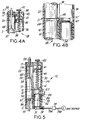
- Figs. 4A and 4B a second embodiment of the liposuction device of the present invention is shown.
- Liposuction device 1B has an alternative cannula assembly retention means while inhering all of the structural features of the first embodiment illustrated in Figs. 1A through 1C.
- liposuction device 1B does not have a hingedly connected housing cover panel, and instead incorporates a snap-fit type cannula assembly retention mechanism.
- actuation element 37' has an extension which is essentially flush with elongated slot 38 formed in cavity wall 22. As shown in Fig. 4B, this extension is provided with a spring biased ball bearing 48 that projects slightly beyond cannula cavity wall surface 22.
- ball bearing 48 engages within indentation ring 49 circumferentially formed about inner cannula base 10'.
- spring biased ball bearing 48 functions as an engaging means for inner cannula base 10'.
- an engaging means for outer cannula base 17' is also realized as a spring biased ball bearing 50 installed through cannula cavity wall 22.
- Outer cannula base 5' is provided with an annular flange 47 and indentation ring 49 circumferentially formed about outer cannula base 17'.
- annular flange 57 establishes surface to surface contact with peripheral surface 58 area of the housing when cannula base 5' is pushed into cannula cavity 20. In this position, ball bearing 50 engages within indentation ring 49 and a snap-fit engagement is established.
- This arrangement serves to retain both inner and outer cannulas 3' and 4 cannula cavity 20', in a releasable manner, as actuation element 37' is caused to reciprocate periodically.
- the outer cannula is simply removed from cannula cavity 20 by quickly pulling on outer cannula tube 5 with a modest degree of force, to overcome the bias force of engaged ball bearing 50.
- the inner cannula is simply removed by quickly pulling on inner cannula tube 4' to overcome bias force of engaged ball bearing 50.
- this cannula assembly retention mechanism can also provide a safety release feature, in that if inner cannula 4', for example, becomes snagged during an operation, it will disengage from the reciprocation means 6 if a proper spring biasing force is selected for ball bearing 50.
- Figs. 10A, 10B and 11 also show inner and outer cannulas adapted for use with liposuction instruments having cannula retention capabilities of the snap-in type described above.
- the elements which correspond to inner and outer cannulas illustrated in Figs. 2A through 2D and 3A through 3E, are indicated by similar reference numbers.
- inner cannula base 10'' has a deeply formed spherical indentation 52 which is adapted to receive ball bearing 48 mounted in the extension of in actuation element 37.
- a longitudinally extending groove 53 is formed in inner cannula base 10''.
- widened recess portions 53A and 53B are provided at opposite ends of groove 53 to facilitate initial insertion of ball bearing 48 in groove 53.
- Fig. 11 shows outer cannula base 17' having a longitudinally extending groove 55. Also, as shown, widened recess portions 55A and 55B are formed at opposite ends of groove 55 to facilitate insertion of ball bearing 50 into spherical indentation 56.
- outer cannula base 17' is slid into cannula cavity 20
- ball bearing 50 snaps into spherical indentation 56 to establish a locked position.
- annular flange 57 will engage with outer peripheral surface 58, about circular access opening leading into cannula cavity, shown in Fig. 4A.
- outer cannula 5 is rendered stationary relative to hand-holdable housing 2.
- the outer cannula is simply removed from cannula cavity 20 by pulling on outer cannula tube 5 with a modest degree of force to overcome the bias force of engaged ball bearing 50.
- piston-type motor 6 can be modified, as shown in Fig. 5, to produce a third embodiment of the liposuction device of the present invention.
- the basic structure of liposuction device 1C is similar to that shown in Figs. 1A through 1C, except that a user-adjustable intermediate housing wall 88 is disposed between the inner walls 31A of chamber housing 31 and the outer walls 34A of movable piston 34.
- Intermediate housing wall 87 is operably associated with an excursion selection means realized as a slidable member 88 fixedly attached to the upper portion of intermediate housing wall 59.
- slidable member 88 extends through a slot 89 formed in the wall of housing 2 and can be slid, for example, by movement of the surgeon's thumb.
- the function of intermediate housing wall 87 is to effectively raise the height of the chamber housing wall, and thus selectively increase distance d, defined, for example, as the distance between gas outlet port 32 in piston 34 and upper portion 63 of the chamber housing wall. In this way, movable piston 34 must undergo a larger displacement before compressed gas will be released and piston 34 permitted to be forced downwardly under the biasing force of biasing spring element 40.
- a conventional gas flow regulation device 78 inserted between source of gas "S" and inlet port 32 of chamber housing 31.
- tubing sections 79A and 79B are used to achieve fluid communication between these elements.
- cannula reciprocation rates will be in the range of 30 to 90 reciprocation cycles per minute, and the corresponding gas flow rates will depend on parameters including, for example, the compliance of biasing spring 40, the volumes of movable piston 34 and chamber housing 31, the cross-sectional diameter of gas inlet port 32, and the cross-sectional diameter of gas outlet ports 36 in the piston.
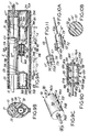
- a fourth embodiment of the liposuction device of the present invention there is shown a fourth embodiment of the liposuction device of the present invention.
- housing 2 and reciprocation means 6 are generally similar to those of the previously described embodiments.
- Cannula assembly 3'' is different, however, in significant respects from that of the previously described embodiments.
- cannula assembly 3'' comprises an inner cannula 4'' stationary relative to housing 2, and an outer cannula sleeve 5'' disposed over the inner cannula and reciprocatable therealong by operably associated reciprocation means 6.
- inner cannula 4'' comprises a hollow tube having a distal end 4A'' and proximal end 4B''.
- Hollow inner tube 4'' has three elongated aspiration apertures 60A, 60B and 60C formed along the distal end, as shown.
- Elongated aspiration apertures 60A, 60B and 60C are in communication with central passageway 62 so as to permit aspiration of fatty tissue through these apertures, along hollow tube 4'' and out of outlet port 63.
- inner cannula base 61 is provided with an annular flange 64 which is releasably received within a matching annular recess 65 formed in the rear most portion of cannula cavity 20, as shown.
- outer cannula 5'' comprises a hollow outer tube (i.e., sleeve) having a distal end 5A'' and a proximal end 5B''.
- a hollow outer tube i.e., sleeve
- three circumferentially spaced-apart, elongated aspiration apertures 67A, 67B and 67C are formed longitudinally in outer sleeve 5'', as shown.
- Extending above each elongated aperture 67A, 67B and 67C is an arcuately shaped projection, 68A, 68B and 68C, respectively. On the sides of each projection are passageways leading through the respective aspiration aperture.
- each projection is approximately equal to the diameter of hollow outer sleeve 5''.
- outer cannula base 69 comprising a cylindrically shaped structure with a central disposed bore 70, through which inner cannula tube 4'' can freely pass.
- a notch 71 is formed in cylindrical outer base 69, into which actuation extension 13 can releasably engage, as shown in Fig. 6A.
- inner cannula 4'' When cannula assembly 3'' is assembled, inner cannula 4'' is inserted within hollow sleeve 5'' and each outer aspiration aperture 67A, 67B and 67C is in at least partial registration with respective elongated inner aspiration apertures 60A, 60B and 60C.
- inner cannula base 61 is stationarily connected within cannula cavity 20, and outer cannula base 69 is engaged with actuation extension 13 and thus is operably associated with reciprocatable motor 6.
- distal tip portion 5C'' of outer cannula sleeve 5'' is provided a keying element 73 which extends radially inward and slides within elongated aperture 60B formed in the wall of inner cannula tube 4A''.
- This keying system prevents the outer cannula sleeve 5'' from axial misalignment as it undergoes reciprocating movement along inner cannula 4''.
- outer cannula sleeve 5'' is slidably moved along inner cannula 4'' so that the general location of aspiration through the partially registered aspiration apertures, is periodically displaced.
- projections 68A, 68B and 68C above outer aspiration apertures 67A, 67B and 67C, respectively, are slidably moved about respective elongated inner aspiration apertures 60A, 60B and 60C.
- outer sleeve portion 5A''' comprises a surface contour in which projections 75A, 75B and 75C are continuously formed and circumferentially spaced about outer sleeve 5B''. Also shown are pairs of aspiration apertures 76 formed in the side walls 77 of each projection. These apertures provide openings through which fatty tissue can be aspired and passed through inner aspiration aperture and along hollow inner tube.
- the essentially continuous surface contours of these projections and aspiration apertures provide reduction in resistance of outer cannula reciprocational movement through tunnels of fatty tissue formed during a liposuction procedure.
- the projections can serve to (i) hold the layers of fatty tissue away from the underlying inner aspiration apertures 60A, 60B and 60C formed in the inner cannula, and/or (ii) facilitate dissection of fatty tissue to be aspirated.
- Liposuction device 1E has an alternative cannula assembly retention means while inhering all of the structural features of the fourth embodiment illustrated in Figs. 6A through 6E.
- liposuction device 1E does not have a hingedly connected cover panel, and instead has a cannula cavity that permits use of snap-fit type cannula assembly components, illustrated for example in Figs. 4A and 4B.
- the extension of actuation element 37' projects essentially flush with elongated slot 38 in cavity wall 22.
- this extension is provided with a spring-biased ball bearing 80 which projects slightly beyond cannula cavity wall surface 22, and engages within indentation ring 81, circumferentially disposed about outer cannula base 69.
- spring biased ball bearing 80 functions as an engaging means for outer cannula base 69.
- Outer cannula 5B'' is retained within cannula cavity 20 as actuation element 371 is caused to reciprocate.
- an engaging means for inner cannula base 61 is also realized as a spring biased ball bearing 82, is installed through cannula cavity wall 22. As shown, ball bearing 82 engages with indentation ring 83, circumferentially disposed about inner cannula base 61.
- This structural arrangement serves to retain inner cannula 4'' stationarily within cannula cavity 20 during operation of liposuction device 1E.
- the cannula bases of the inner and outer cannulas shown in Figs. 10A and 10B, can also be adapted for use as inner and outer cannula bases for the cannula assembly utilized in liposuction device 1E of Fig. 7.
- Cannula assembly 3''' of the illustrated embodiment includes an inner cannula and an outer cannula comprising hollow inner and outer tubes 4''' and 5''', respectively.
- inner cannula 4''' also includes inner cannula base 61 as described above
- outer cannula 5''' includes outer cannula base 69, also described above.
- Inner tube 4''' has three circumferentially spaced apart, elongated aspiration apertures 60A, 60B and 60C which extend along the longitudinal extent of the distal end 4A''' of inner cannula tube 4''', as shown.
- Outer sleeve 5''' has three circumferentially spaced apart aspiration apertures 67A, 67B and 67C. As in the previous embodiment of Figs. 6A through 6C, these aspiration apertures are axially aligned with elongated apertures 60A, 60B and 60C, respectively, that is, when inner cannula 4''' is slidably inserted into outer cannula 5'''.
- distal end 5A''' of outer sleeve 5''' is provided with a keying system.
- the keying system comprises keying element 73 which extends radially inward and slides within elongated aperture 60B, thereby preventing axial rotation between the cannulas as they are under relative reciprocation during liposuction instrument operation.
- Assembly of cannula assembly 3'' is similar to that of cannula assembly 3'' shown in Figs. 3A through 3D.
- distal tip 4C''' of inner cannula 4''' is inserted through bore 70 in outer cannula base 69 so that distal end 4A''' of inner cannula 4''' is slidably received within outer cannula sleeve 5''' and extends therebeyond, as shown in Fig. 8B.
- keying element 73 is received and guided within elongated aperture 60B as shown in Fig 8D.
- cannula assembly 3''' is installed within cannula cavity 20 by first opening hinged cover panel which provides access to the interior of cannula cavity 20. Then inner cannula base flange 64 is inserted within annular recess 65 and actuation extension 13 within outer cannula base notch 71. Thereafter, the housing cover panel is closed shut and liposuction device 1E is ready for operation.
- cannula assemblies 3, 3', 3'' and 3''' and other embodiments of cannula assemblies of the present invention can be made of a variety of materials, including, for example, stainless steel and plastic.
- Stainless steel offers the advantage of being easily cleaned and sterilizable, while plastic offers the advantage of low manufacturing cost and disposability.
- injection molding processes can be used to form integrally molded inner cannulas and integrally molded outer cannulas, each having desired characteristics.
- the molded cannulas would be subsequently sterilized and packaged together. It is expected that in certain applications it may be desirable to form one of the cannulas from plastic material, and the other cannula from metal.
- a liposuction device of the present invention In the surgical environment, the surgeon can simply remove a selected cannula assembly from its sterilized package, and insert the cannula assembly into the cannula cavity of a liposuction device of the present invention.
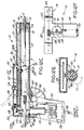
- Figs. 9A through 9D there is shown a sixth embodiment of the liposuction device of the present invention.
- the housing and cannula assembly are generally similar to those of the previously described embodiments, with the exception of several differences which will be described below.
- a pair of piston-type motors 6A and 6B of the type generally indicated in Figs. 1A through 1C and 5, are fixedly installed within respective motor cavities 30A and 30B of housing 2.
- Each piston-type motor 6A and 6B has a respective chamber housing and movable piston, indicated by 31A and 31B, and 34A and 34B, respectively.
- Actuation elements 37A and 37B are fixedly connected to respective pistons 34A and 34B and project through respective elongated slots 38A and 38B formed in cannula cavity wall 22; this is achieved, in a manner similar to that described in connection with the embodiments shown in Figs. 1A through 1C, 4A, 4B and 5. While not shown in Fig.
- a rod or bar is fixedly attached between actuation elements 37A and 37B in order to maintain them a fixed distance apart, and yet provide an operable connection between the inner cannula 41 and actuation elements 37A and 37B in the manner described below.
- this embodiment includes hinged cover panel 21 in a manner similar to that described in the embodiments of Figs. 1A, 1C, 5, 6A and 8A.
- inner cannula base 10''' has first and second receiving slots or notches 12A and 12B, into which extensions 13A and 13B of respective actuation elements 37A and 37B are received.
- Such operable connections between movable pistons 6A and 6B and inner cannula base 10''' enables inner cannula 4' to reciprocate relative to housing 2 when actuation elements 37A and 37B are caused to reciprocate relative to respective gas driven motors 6A and 6B.
- a mechanically-operated gas flow control device 90 is provided in order to control the filling and venting of chambers 33A and 33B of the first and second piston motors, to effectuate cyclical reciprocating motion of actuation elements 37A and 37B and thus inner cannula 4'.
- gas flow control device 90 is employed in operable association with an external source of pressurized gas (not shown), gas inlet ports 32A and 32B, and movable pistons 34A and 34B.
- gas flow control device 90 comprises a shuttle valve housing or casing 91, having first and second shuttle chambers 92A and 92B. These shuttle chambers are separated by a shuttle valve member 93 which is fixedly attached to a slidable shaft 94. As illustrated, shuttle valve member 93 is slidable between two positions or states "A" and "B". In order to achieve this shaft 94 extends through bores 95A and 95B formed in shuttle chamber end walls 91A and 91B respectively, in which seals 96A and 96B are installed in a conventional manner. When the shuttle valve 93 is centrally disposed in casing 91 between states A and B, shaft ends 94A and 94B protrude equally beyond respective bores 95A and 95B.
- a first gas exit port 89A Adjacent one end of cylindrical shuttle chamber side wall 98, a first gas exit port 89A is formed, whereas adjacent the other end of wall 98, a second gas exit port 98B is formed, as shown.
- a gas inlet port 100 is formed in shuttle chamber side wall 98.
- a pair of annulus-shaped shuttle valve stops 101A and 101B are formed at opposite end portions of the interior surface of cylindrical wall 98. These stops 101A and 101B serve to limit sliding movement of shuttle valve 93 when shaft 94 is displaced in one of two possible axial directions by actuation elements 37A and 37B, respectively, as shown in Fig. 9A. As will be discussed in greater detail hereinafter, it is these actuation elements 37A and 37B which displace shaft 94 and thus shuttle valve 93 between one of two states, as movable pistons 34A and 34B are caused to reciprocate.
- shuttle valve 93 is formed of a ferromagnetic material so that ferrous end walls 102A and 102B will attract ferromagnetic shuttle valve 93 and pull it against one of stops 101A and 101B and into gas flow state A or B, i.e., when shuttle valve 93 is brought into proximity therewith upon displacement of shaft 94 by one of actuation elements 37A and 37B.
- Peripheral side surfaces of shuttle valve 93 are provided with seals 103 to prevent gas leakage between shuttle chambers 92A and 92B.
- first gas exit port 99A of device 90 is in a fluid communication with second chamber housing 31B by gas channel 104, whereas second gas exit port 99B is in fluid communication with first chamber housing 31A by gas channel 105.
- gas inlet aperture 106 is formed through housing 2 and permits gas channel 107 to establish fluid communication between gas inlet port 100 and the external source of pressurized gas.
- chamber housings 31A and 31B, shuttle valve housing 91, gas channels 104, 105 and 107 can be realized as discrete elements, as shown, or alternatively as integrally formed elements which are part of the interior of the hand-holdable housing itself.
- gas flow control device 90 The principal function of gas flow control device 90 is to control the flow of gas to pistons 34A and 34B so that only one of the gas pistons is actively driven at a time, while the other is passively driven.
- the manner of operation of gas flow control device 90 in cooperation with the periodic displacement of pistons 34A and 34B, will now be described.
- shuttle valve 93 Owning to the fact that shuttle valve 93 is magnetically biased to be in essentially one of two possible positions, or gas flow states, gas will initially be caused to flow into one of piston-chamber housings 31A or 31B, and cause its respective piston and actuation element to move away (i.e., protract) from its respective chamber housing. Only along a small portion of the piston excursion will shuttle valve shaft 94 and thus shuttle valve 93, be displaced within shuttle valve housing 91 as the actively driven piston is displaced upon buildup of pressurized gas within its respective chamber.
- gas flow control valve 90 is initially in state A, as shown in Fig. 9A.
- piston 34A has reached its maximal displacement and pressurized gas within chamber 33A has been substantially vented through gas outlet port 26A and through ports 39A and 39B.
- shuttle valve 90 is magnetically biased against stops 101B so that gas is caused to flow from the external gas source (not shown), through first shuttle chamber 92A and into second chamber housing 33B.
- shuttle valve 93 With shuttle valve 93 in this state, gas pressure is allowed to build up in chamber 33B, displacing piston 34B and actuation element 37B to protract from second chamber housing 31B.
- inner cannula base 10''' is caused to undergo an outwardly directed excursion within cannula cavity 20, commensurate with the active displacement of piston 34B.
- piston excursion i.e., travel
- shuttle valve 93 remains in state A against stop 101B.
- actuation element 37B contacts shaft end 94B and displaces shuttle valve 93 away from stop 101B to about mid-position in shuttle housing 91, approximately over input port 100, at which point, magnetic shuttle valve 93 is pulled toward ferrous plate 102A into state B and against stop 101A, as shown in Fig. 9A with phantom lines.
- gas flow control device 90 directs the flow of pressurized gas from the external source, along channel 107, through second shuttle chamber 92B and along channel 105 and into piston chamber housing 31A.
- Magnetically biased shuttle valve 93 remains in state B as chamber housing 31A fills with pressurized gas, expanding the chamber 33A and actively displacing piston 34A away from chamber housing 31A, while causing piston 34B to passively retract back into its chamber housing 31B. All the while, inner cannula base 10''', being operably associated with actuation elements 37A and 37B, undergoes a commensurate amount of inwardly directed excursion within cannula cavity 20.
- actuation element 37A contacts shaft end 94A and displaces shuttle valve 93 a small distance L5, at which point, magnetic shuttle valve 93 is pulled towards ferrous plate 102B, back into state A and against stop 101B.
- gas flow control device 90 directs the flow of pressurized gas from the external source, along channel 107, through first shuttle chamber 92A, along channel 104 and into piston chamber housing 31B.
- Magnetically biased shuttle valve 93 remains in state A as chamber housing 91B fills with pressurized gas, expanding chamber 3B actively displacing piston 34B away from chamber housing 31B, while causing piston 34A to passively retract back into its piston chamber housing 31A. All the while, inner cannula base 10''', being operably associated with actuation elements 37A and 37B, undergoes once again a commensurate amount of outwardly directed excursion within cannula cavity 20. With a preselected gas pressure and flow rate set at gas inlet port 100 of device 90, the above-described process of gas filling, venting and flow control occurs automatically at a corresponding rate, resulting in periodic reciprocation of inner cannula 10''' relative to hand-holdable housing 2. In turn, this periodic reciprocation of inner cannula 4' results in periodic displacement of the general location of aspiration occurring along the length of the cannula assembly.
- liposuction device 1G has a pistol-shaped housing 110 which comprises a barrel portion 111 and a detachable handle portion 112.
- this embodiment utilizes a rotary-type motor 113.
- rotary-type motor 113 In operative association with a cam mechanism, generally indicated by reference numeral 114, rotary-type motor 113 causes actuation element 115 to cyclically slide back and forth and cause inner cannula 4' to periodically reciprocate relative to barrel portion 111 of the pistol-shaped housing.
- barrel portion 111 of the housing comprises a cannula cavity 116 adapted for slidably receiving cylindrically-shaped base 17 of inner cannula 4', in a manner described hereinabove.
- Cannula cavity 116 is also provided with a longitudinally extending access opening, over which a hingedly connected cover panel 117 is provided.
- cover panel 117 facilitates insertion of the cannula assembly into, and removal of the cannula assembly from, cannula cavity 116 in a manner similar to that described in connection with liposuction instrument 1A of Figs. 1A through 1C, in particular.
- inner cannula base 10 is adapted to be received within cannula cavity 116 and outer cannula base flange 19 releasably received within annular recess 118 formed in cannula cavity wall 22.
- inner cannula 4' into cannula cavity 116, semi-flexible transparent tubing 15 is connected to inner cannula outlet port 11. Then cover panel 117 is opened and tubing 15 fed out through rear port 119 of the barrel portion, as illustrated in Figs. 12C and 12F. Inner cannula base 10 is then slid into cavity 116 with extensional portion of actuation element 115 received in notch 12. Then outer cannula 5' is slid over the distal end of inner cannula 4' until outer cannula base 17 is received within annular recess 118. Thereafter, as shown in Fig. 12E, cover panel 117 is snapped closed using, for example, a spring biased locking device 120, of the type previously described above. Removal of inner and outer cannulas simply involves a reversal of the above procedure.
- barrel portion 111 can be realized without necessity of hinged cover panel 117.
- the inner and outer cannulas can be snap-fitted into and pulled out of cannula cavity 116 in a manner similar to that described hereinabove.
- barrel portion 111 houses cam mechanism 114 which is operably associated with (i) rotary motor 113 contained within the handle portion, and (ii) actuation element 115 which slidably passes through a longitudinal slot 121 formed within the upper wall of cannula cavity 116.
- actuation element 115 includes extension 115A that passes through elongated slot 121 and is received within notch 12 formed in inner cannula base 10.
- cam mechanism 114 of the illustrated embodiment inherently embodies gear reduction. In this way, a high angular shaft velocity of rotary motor 113, can be efficiently transformed into reciprocational strokes of the cannula, occurring at a substantially lower rate.
- actuation element 115 is caused to reciprocate within elongated slot 121 by way of cam mechanism 114, and thereby cause inner cannula 4' to periodically reciprocate relative to housing 110. This motion results in periodic displacement of the general location of aspiration occurring along the length of the cannula assembly.
- cam mechanism 114 of the preferred embodiment comprises a drive wheel 122 having a first predetermined number of gear teeth 123 disposed thereabout.
- Drive wheel 122 is rotatably mounted to a shaft 124 mounted through and opening in the top panel of an accommodating section 125 of the barrel portion.
- Cam mechanism 114 also includes a connective element 126 having first and second ends 126A and 126B, respectively.
- First end 126A of the connective element is pivotally attached to the drive wheel 122 at a point disposed away from the axial center 124, whereas second end 126B is pivotally connected to actuation element 115 as shown.
- a radially formed slot 127 is formed in drive wheel 122.
- a plurality of widened circular apertures 128 are disposed along radial slot 127 as shown in Figs. 12B and 12D.
- a spring-loaded cylindrical pin 129 passing through the first end of connective element 126 can be selectively locked into one of apertures 128 by pulling upwardly upon pin 129 and setting its cylindrical base 129A into the desired aperture 128.
- pin 129 is shown to further include pin head 129B, a hollow bore 129B, and an axle 129D having heads 129E and 129F.
- a spring 129G is enclosed within bore 129C, about axle 129D and between head 129F and an inner flange 129H.
- spring loaded pin 129 By selectively locking the first end 126A of connective element 126 into a particular circular notch 128 using spring loaded pin 129, the distance of the first end of the connective element from axial center 124 can be set, and thus the amount of inner cannula excursion (and effective aspiration aperture displacement) thereby selected.
- the top panel of accommodating portion 125 of the housing is provided with a hinged door 132 that can be opened and snapped closed as desired.
- handle portion 112 of the housing encloses a substantial portion of rotary motor 113 whose shaft 133 projects beyond the handle portion and bears a gear wheel 134.
- gear wheel 134 has a second predetermined number of gear teeth 134A disposed circumferentially thereabout, which mesh with drive wheel teeth 123.
- shaft 133 of the motor is mounted off center of handle portion 113, as shown in Figs. 12C and 12F.
- Rotary motor 113 is preferably an electric motor whose shaft speed is controllable by the voltage applied to its terminals.
- Such speed control can be realized by a conventional speed control circuit 135 connected between motor 113 and a conventional 110-115 volt, 50-60 Hertz power supply.
- conventional electrical cord 136 and on/off power switch 150 can be used to connect control circuit 135 and the power supply.
- Control over the output voltage produced from speed control circuit 115 and provided to electrical motor 113 can be adjusted, for example, by changing the resistance of a potentiometer 137 which is operably connected to the speed control circuit.
- a potentiometer 137 which is operably connected to the speed control circuit.
- this potentiometer 137 can be embodied within a trigger mechanism 138 which is connected, for example, to handle portion 112 of housing 110.
- trigger mechanism 138 By pulling trigger 138, the speed of rotary motor 113 can be controlled, and consequently, so too the rate of reciprocation of inner cannula 4' relative to outer cannula 5', and thus the rate of displacement of the effective aspiration apertures.
- handle portion 112 To connect handle portion 112 to barrel portion 111 and permit disconnection therebetween for cleaning, sterilization and general service, handle portion 112 is provided with flange 140 and thumb-operable spring element 141.
- Barrel portion 111 On the other hand, is provided with slot 142, catch 143, and cavity 144.
- shaft 133 is vertically passed through channels 144 and 145 until gear 134 is slightly below the plane of drive wheel 122. Then, spring element 141 is inserted within cavity 144 while flange 140 is guided into slot 142. By pushing the rear portion of handle 112 in the longitudinal direction of cannula cavity 116, spring element 141 will snap over and clasp catch 143 as shown in Fig. 12C.
- handle portion 112 is secured to barrel portion 111 and gear teeth 123 will mesh with drive wheel teeth 134A.
- the surgeon's thumb simply depresses spring-element 141 downwardly and then, by moving handle portion 112 slightly rearwardly, then downwardly, flange 140 is dislodged from slot 142 and motor shaft 133 can be withdrawn from channels 144 and 145.
- handle portion 110 and barrel portion 112 can be individually cleaned and sterilized using conventional procedures known in the surgical instrument art.
- Liposuction device 1G described above employed an electric rotary motor to effectuate reciprocation of inner cannula 4' relative to housing 110.
- trigger 138 can be operatively associated with a gas flow control valve.
- the rate of gas flow to the gas rotary motor upon actuation of trigger 138 the angular velocity of shaft 133 can be controlled and thus the rate of reciprocation of inner cannula 4' relative to housing 110.
- the surgeon prepares in a conventional manner, the area of skin below which liposuction is to be performed. Typically, this entails marking various zones where radial displacement of the aspiration apertures are to occur.
- Liposuction instrument 1C of the present invention is assembled as described above so that aspiration apertures 8A', 8B' and 8C' of cannula assembly 3' are in communication with a vacuum source (not shown). A small incision is then made in the patient's skin in a conventional manner, and the distal portion of the cannula assembly is inserted into a premarked radial zone.
- inner cannula 10 will automatically reciprocate causing the general location of the suction apertures to be automatically displaced along each tunnel of fatty tissue.
- the surgeon's hand holding the liposuction instrument is maintained essentially stationary with respect to the patient.
- Fatty tissue is aspirated through the periodically displaced aspiration apertures, and transferred into a reservoir tank operably associated with the vacuum source.
- the surgeon can selectively increase the rate of aspiration aperture travel along the distal end of the cannula assembly. This can be achieved by a foot-operated gas flow control device 78 which controls the rate of gas flow to piston motor 6. Also, the amount of inner cannula excursion (i.e., aspiration aperture travel) can also be selected by adjusting the compliance of spring 40 through rotation of threaded element 42.
Landscapes
- Health & Medical Sciences (AREA)
- Surgery (AREA)
- Heart & Thoracic Surgery (AREA)
- Life Sciences & Earth Sciences (AREA)
- Engineering & Computer Science (AREA)
- General Health & Medical Sciences (AREA)
- Biomedical Technology (AREA)
- Veterinary Medicine (AREA)
- Public Health (AREA)
- Animal Behavior & Ethology (AREA)
- Vascular Medicine (AREA)
- Anesthesiology (AREA)
- Hematology (AREA)
- Orthopedic Medicine & Surgery (AREA)
- Nuclear Medicine, Radiotherapy & Molecular Imaging (AREA)
- Medical Informatics (AREA)
- Molecular Biology (AREA)
- External Artificial Organs (AREA)
Priority Applications (3)
| Application Number | Priority Date | Filing Date | Title |
|---|---|---|---|
| US07/627,240 US5348535A (en) | 1990-12-14 | 1990-12-14 | Power-assisted liposuction instrument and cannula assembly therefor |
| DE1994631798 DE69431798T2 (de) | 1994-09-19 | 1994-09-19 | Kraftunterstütztes Fettabsauggerät und Kanüleanordnung dafür |
| EP94306845A EP0701825B1 (fr) | 1990-12-14 | 1994-09-19 | Appareil de liposuccion à mouvement assisté et ensemble de canule pour cet appareil |
Applications Claiming Priority (2)
| Application Number | Priority Date | Filing Date | Title |
|---|---|---|---|
| US07/627,240 US5348535A (en) | 1990-12-14 | 1990-12-14 | Power-assisted liposuction instrument and cannula assembly therefor |
| EP94306845A EP0701825B1 (fr) | 1990-12-14 | 1994-09-19 | Appareil de liposuccion à mouvement assisté et ensemble de canule pour cet appareil |
Publications (2)
| Publication Number | Publication Date |
|---|---|
| EP0701825A1 true EP0701825A1 (fr) | 1996-03-20 |
| EP0701825B1 EP0701825B1 (fr) | 2002-11-27 |
Family
ID=26137298
Family Applications (1)
| Application Number | Title | Priority Date | Filing Date |
|---|---|---|---|
| EP94306845A Expired - Lifetime EP0701825B1 (fr) | 1990-12-14 | 1994-09-19 | Appareil de liposuccion à mouvement assisté et ensemble de canule pour cet appareil |
Country Status (2)
| Country | Link |
|---|---|
| US (1) | US5348535A (fr) |
| EP (1) | EP0701825B1 (fr) |
Cited By (3)
| Publication number | Priority date | Publication date | Assignee | Title |
|---|---|---|---|---|
| BE1011084A5 (fr) * | 1997-04-03 | 1999-04-06 | Jean Malak | Appareil de lipo-aspiration. |
| FR2831823A1 (fr) | 2001-11-07 | 2003-05-09 | Saphir Medical | Appareil de liposuccion a jet de liquide sous pression et procede de liposuccion utilisant cet appareil |
| WO2006126195A1 (fr) * | 2005-05-27 | 2006-11-30 | Ishay Wohl | Systeme et procede chirurgical |
Families Citing this family (31)
| Publication number | Priority date | Publication date | Assignee | Title |
|---|---|---|---|---|
| US5928218A (en) * | 1994-12-16 | 1999-07-27 | Gelbfish; Gary A. | Medical material removal method and associated instrumentation |
| US5520635A (en) * | 1994-12-16 | 1996-05-28 | Gelbfish; Gary A. | Method and associated device for removing clot |
| US6102885A (en) | 1996-08-08 | 2000-08-15 | Bass; Lawrence S. | Device for suction-assisted lipectomy and method of using same |
| EP0830846B1 (fr) | 1996-09-24 | 2004-01-14 | Xomed Surgical Products, Inc. | Pièce à main actionnée |
| US5911700A (en) * | 1997-03-11 | 1999-06-15 | Microaire Surgical Instruments | Power assisted liposuction and lipoinjection equipment |
| US6071260A (en) * | 1997-09-18 | 2000-06-06 | The California Institute Of Tissue Engineering And Instrumentation, Llc | Ultrasonic liposuction device and a method of using the same |
| USD408529S (en) * | 1997-12-23 | 1999-04-20 | Fibrasonics Inc. | Cannula for ultrasonic probe |
| USD409746S (en) * | 1997-12-23 | 1999-05-11 | Fibrasonics Inc. | Cannula for an ultrasonic probe |
| US6033375A (en) * | 1997-12-23 | 2000-03-07 | Fibrasonics Inc. | Ultrasonic probe with isolated and teflon coated outer cannula |
| USD478165S1 (en) | 1997-12-23 | 2003-08-05 | Misonix Incorporated | Cannula for ultrasonic probe |
| US6270471B1 (en) | 1997-12-23 | 2001-08-07 | Misonix Incorporated | Ultrasonic probe with isolated outer cannula |
| US6375648B1 (en) | 1998-10-02 | 2002-04-23 | Misonix Incorporated | Infiltration cannula with teflon coated outer surface |
| US6129701A (en) | 1998-11-19 | 2000-10-10 | Sound Surgical Technologies, Llc | Vented aspirator and method |
| US6716194B1 (en) | 2001-05-04 | 2004-04-06 | Sound Surgical Technologies Llc | Surgical aspiration device employing continuous, precise venting |
| US6676677B2 (en) * | 2001-05-11 | 2004-01-13 | Jeffrey A. Klein | Liposuction cannula with abrading apertures |
| US7641668B2 (en) | 2003-05-16 | 2010-01-05 | Scimed Life Systems, Inc. | Fluid delivery system and related methods of use |
| US20040236307A1 (en) * | 2003-05-21 | 2004-11-25 | Klein Jeffrey A. | Infiltration cannula |
| US20040236313A1 (en) | 2003-05-21 | 2004-11-25 | Klein Jeffrey A. | Infiltration cannula |
| US8105310B2 (en) | 2003-05-21 | 2012-01-31 | Klein Jeffrey A | Infiltration cannula |
| US20060200085A1 (en) * | 2005-02-15 | 2006-09-07 | Philip Watts | Tissue transfer cannula and connectors |
| WO2007005902A2 (fr) * | 2005-07-01 | 2007-01-11 | Bio-Matrix Scientific Group Inc. | Dispositif de serrage de seringue |
| WO2007038433A2 (fr) * | 2005-09-23 | 2007-04-05 | Bio-Matrix Scientific Group Inc. | Manche et systeme de rangement de canule |
| US20090275960A1 (en) * | 2008-04-08 | 2009-11-05 | John Mark Provenza | Apparatus and method for gastric reduction |
| US20110213336A1 (en) | 2009-08-05 | 2011-09-01 | Cucin Robert L | Method of and apparatus for sampling, processing and collecting tissue and reinjecting the same into human patients |
| US8348929B2 (en) | 2009-08-05 | 2013-01-08 | Rocin Laboratories, Inc. | Endoscopically-guided tissue aspiration system for safely removing fat tissue from a patient |
| US20110306950A1 (en) * | 2010-06-10 | 2011-12-15 | Cucin Robert L | Coaxially-Driven Tissue Aspiration Instruments |
| US8465471B2 (en) | 2009-08-05 | 2013-06-18 | Rocin Laboratories, Inc. | Endoscopically-guided electro-cauterizing power-assisted fat aspiration system for aspirating visceral fat tissue within the abdomen of a patient |
| CN102781509A (zh) | 2009-11-30 | 2012-11-14 | 杰弗里·艾伦·克莱因 | 肿胀抗生素溶液 |
| CN104822398B (zh) * | 2012-09-14 | 2017-06-09 | 史赛克公司 | 可释放地联接到电动手术手持件并由其供应动力的医疗/手术冲洗器 |
| CN108030519B (zh) * | 2017-12-06 | 2023-08-15 | 山西阳光中天医疗器械有限公司 | 一种气动吸脂装置 |
| EP3928723A1 (fr) * | 2020-06-24 | 2021-12-29 | Avister-Medical | Dispositif, dispositif de commande, système et procédé de liposuccion |
Citations (4)
| Publication number | Priority date | Publication date | Assignee | Title |
|---|---|---|---|---|
| DE330284C (de) * | 1919-09-19 | 1920-12-11 | Albrecht Meyenberg Dr | Vorrichtung zur Entfernung eitriger Sekrete aus der Harnroehre |
| EP0125070A2 (fr) * | 1983-04-27 | 1984-11-14 | Olympus Optical Co., Ltd. | Appareil chirurgical pour couper |
| FR2648050A1 (fr) * | 1989-06-08 | 1990-12-14 | Bouvier Pierre | Dispositif pour aspirer et evacuer les depots graisseux dans les tissus adipeux |
| US5112302A (en) * | 1990-07-16 | 1992-05-12 | Cucin Robert L | Method and apparatus for performing liposuction |
Family Cites Families (22)
| Publication number | Priority date | Publication date | Assignee | Title |
|---|---|---|---|---|
| US3082805A (en) * | 1960-12-21 | 1963-03-26 | John H Royce | Tissue macerator |
| US3732858A (en) * | 1968-09-16 | 1973-05-15 | Surgical Design Corp | Apparatus for removing blood clots, cataracts and other objects from the eye |
| US3734099A (en) * | 1971-04-07 | 1973-05-22 | H Bender | Powered surgical cutter |
| US3955579A (en) * | 1973-07-23 | 1976-05-11 | Henry Bridgman | Vacuum curet |
| US3994297A (en) * | 1974-12-09 | 1976-11-30 | Kopf J David | Ophthalmic instrument |
| US4311140A (en) * | 1976-05-10 | 1982-01-19 | Henry Bridgman | Vacuum curet having an improved curetting opening |
| US4167944A (en) * | 1977-06-27 | 1979-09-18 | Surgical Design Corp. | Rotatable surgical cutting instrument with improved cutter blade wear |
| US4203444A (en) * | 1977-11-07 | 1980-05-20 | Dyonics, Inc. | Surgical instrument suitable for closed surgery such as of the knee |
| US4314560A (en) * | 1979-11-28 | 1982-02-09 | Helfgott Maxwell A | Powered handpiece for endophthalmic surgery |
| US4487600A (en) * | 1981-11-09 | 1984-12-11 | Brownlie Alan W | Adjustable suction device for medical use |
| US4530356A (en) * | 1983-02-08 | 1985-07-23 | Helfgott Maxwell A | Ophthalmic surgical instrument with beveled tip |
| US4536180A (en) * | 1983-07-22 | 1985-08-20 | Johnson Gerald W | Surgical instrument for suction lipolysis |
| US4577629A (en) * | 1983-10-28 | 1986-03-25 | Coopervision, Inc. | Surgical cutting instrument for ophthalmic surgery |
| US4932935A (en) * | 1986-09-15 | 1990-06-12 | Barry Swartz | Assisted lipectomy device |
| US4735605A (en) * | 1986-09-15 | 1988-04-05 | Swartz Barry E | Lipectomy device having round cutting edges |
| US4775365A (en) * | 1986-09-15 | 1988-10-04 | Barry Swartz | Lipectomy cannula |
| US4815462A (en) * | 1987-04-06 | 1989-03-28 | Clark Vickie J | Lipectomy device |
| US4850354A (en) * | 1987-08-13 | 1989-07-25 | Baxter Travenol Laboratories, Inc. | Surgical cutting instrument |
| US4909249A (en) * | 1987-11-05 | 1990-03-20 | The Cooper Companies, Inc. | Surgical cutting instrument |
| US4940468A (en) * | 1988-01-13 | 1990-07-10 | Petillo Phillip J | Apparatus for microsurgery |
| US4886491A (en) * | 1988-02-29 | 1989-12-12 | Tulio Parisi | Liposuction procedure with ultrasonic probe |
| US5024652A (en) * | 1988-09-23 | 1991-06-18 | Dumenek Vladimir A | Ophthalmological device |
-
1990
- 1990-12-14 US US07/627,240 patent/US5348535A/en not_active Expired - Lifetime
-
1994
- 1994-09-19 EP EP94306845A patent/EP0701825B1/fr not_active Expired - Lifetime
Patent Citations (4)
| Publication number | Priority date | Publication date | Assignee | Title |
|---|---|---|---|---|
| DE330284C (de) * | 1919-09-19 | 1920-12-11 | Albrecht Meyenberg Dr | Vorrichtung zur Entfernung eitriger Sekrete aus der Harnroehre |
| EP0125070A2 (fr) * | 1983-04-27 | 1984-11-14 | Olympus Optical Co., Ltd. | Appareil chirurgical pour couper |
| FR2648050A1 (fr) * | 1989-06-08 | 1990-12-14 | Bouvier Pierre | Dispositif pour aspirer et evacuer les depots graisseux dans les tissus adipeux |
| US5112302A (en) * | 1990-07-16 | 1992-05-12 | Cucin Robert L | Method and apparatus for performing liposuction |
Cited By (5)
| Publication number | Priority date | Publication date | Assignee | Title |
|---|---|---|---|---|
| BE1011084A5 (fr) * | 1997-04-03 | 1999-04-06 | Jean Malak | Appareil de lipo-aspiration. |
| FR2831823A1 (fr) | 2001-11-07 | 2003-05-09 | Saphir Medical | Appareil de liposuccion a jet de liquide sous pression et procede de liposuccion utilisant cet appareil |
| WO2003039629A1 (fr) | 2001-11-07 | 2003-05-15 | Eschmann Holdings Limited | Appareil de liposuccion |
| US7056315B2 (en) | 2001-11-07 | 2006-06-06 | Eschmann Holdings Limited | Liposuction apparatus with pressurized liquid spray and liposuction method using the apparatus |
| WO2006126195A1 (fr) * | 2005-05-27 | 2006-11-30 | Ishay Wohl | Systeme et procede chirurgical |
Also Published As
| Publication number | Publication date |
|---|---|
| EP0701825B1 (fr) | 2002-11-27 |
| US5348535A (en) | 1994-09-20 |
Similar Documents
| Publication | Publication Date | Title |
|---|---|---|
| US5643198A (en) | Power-assisted liposuction instrument and cannula assembly therefor | |
| EP0701825B1 (fr) | Appareil de liposuccion à mouvement assisté et ensemble de canule pour cet appareil | |
| US5112302A (en) | Method and apparatus for performing liposuction | |
| US6346107B1 (en) | Power-assisted liposuction instrument with cauterizing cannual assembly | |
| US6394973B1 (en) | Power-assisted liposuction instrument with cauterizing cannula assembly | |
| US7384417B2 (en) | Air-powered tissue-aspiration instrument system employing curved bipolar-type electro-cauterizing dual cannula assembly | |
| US20120157944A1 (en) | Method of installing a cannula assembly within a coaxially-driven tissue aspiration instrument | |
| KR100220551B1 (ko) | 수술도구 운반, 조종 및 추출을 위한 의료형 선형 액추에이터 | |
| US5176628A (en) | Vitreous cutter | |
| US4775365A (en) | Lipectomy cannula | |
| US4792327A (en) | Lipectomy cannula | |
| US8685052B2 (en) | Devices and methods for cutting tissue | |
| AU2011272778B2 (en) | Devices and methods for cutting and evacuating tissue | |
| CN104736075B (zh) | 用于切除组织的装置和方法 | |
| CN110151259A (zh) | 通电组织切除装置 | |
| CN212547025U (zh) | 一种脉管治疗仪 | |
| CA2132395A1 (fr) | Instrument de liposuccion a commande asistee et son systeme de canules | |
| DE69431798T2 (de) | Kraftunterstütztes Fettabsauggerät und Kanüleanordnung dafür |
Legal Events
| Date | Code | Title | Description |
|---|---|---|---|
| PUAI | Public reference made under article 153(3) epc to a published international application that has entered the european phase |
Free format text: ORIGINAL CODE: 0009012 |
|
| AK | Designated contracting states |
Kind code of ref document: A1 Designated state(s): DE DK FR GB IT NL SE |
|
| 17P | Request for examination filed |
Effective date: 19960912 |
|
| 17Q | First examination report despatched |
Effective date: 19991126 |
|
| GRAG | Despatch of communication of intention to grant |
Free format text: ORIGINAL CODE: EPIDOS AGRA |
|
| GRAG | Despatch of communication of intention to grant |
Free format text: ORIGINAL CODE: EPIDOS AGRA |
|
| GRAH | Despatch of communication of intention to grant a patent |
Free format text: ORIGINAL CODE: EPIDOS IGRA |
|
| GRAH | Despatch of communication of intention to grant a patent |
Free format text: ORIGINAL CODE: EPIDOS IGRA |
|
| GRAA | (expected) grant |
Free format text: ORIGINAL CODE: 0009210 |
|
| RAP1 | Party data changed (applicant data changed or rights of an application transferred) |
Owner name: ROCIN LABORATORIES, INC. |
|
| AK | Designated contracting states |
Kind code of ref document: B1 Designated state(s): DE DK FR GB IT NL SE |
|
| PG25 | Lapsed in a contracting state [announced via postgrant information from national office to epo] |
Ref country code: NL Free format text: LAPSE BECAUSE OF FAILURE TO SUBMIT A TRANSLATION OF THE DESCRIPTION OR TO PAY THE FEE WITHIN THE PRESCRIBED TIME-LIMIT Effective date: 20021127 |
|
| REG | Reference to a national code |
Ref country code: GB Ref legal event code: FG4D |
|
| REF | Corresponds to: |
Ref document number: 69431798 Country of ref document: DE Date of ref document: 20030109 |
|
| PG25 | Lapsed in a contracting state [announced via postgrant information from national office to epo] |
Ref country code: SE Free format text: LAPSE BECAUSE OF FAILURE TO SUBMIT A TRANSLATION OF THE DESCRIPTION OR TO PAY THE FEE WITHIN THE PRESCRIBED TIME-LIMIT Effective date: 20030227 Ref country code: DK Free format text: LAPSE BECAUSE OF FAILURE TO SUBMIT A TRANSLATION OF THE DESCRIPTION OR TO PAY THE FEE WITHIN THE PRESCRIBED TIME-LIMIT Effective date: 20030227 |
|
| NLV1 | Nl: lapsed or annulled due to failure to fulfill the requirements of art. 29p and 29m of the patents act | ||
| ET | Fr: translation filed | ||
| PLBE | No opposition filed within time limit |
Free format text: ORIGINAL CODE: 0009261 |
|
| STAA | Information on the status of an ep patent application or granted ep patent |
Free format text: STATUS: NO OPPOSITION FILED WITHIN TIME LIMIT |
|
| 26N | No opposition filed |
Effective date: 20030828 |
|
| PGFP | Annual fee paid to national office [announced via postgrant information from national office to epo] |
Ref country code: IT Payment date: 20080926 Year of fee payment: 15 Ref country code: FR Payment date: 20080915 Year of fee payment: 15 |
|
| PGFP | Annual fee paid to national office [announced via postgrant information from national office to epo] |
Ref country code: GB Payment date: 20080924 Year of fee payment: 15 |
|
| PGFP | Annual fee paid to national office [announced via postgrant information from national office to epo] |
Ref country code: DE Payment date: 20081002 Year of fee payment: 15 |
|
| GBPC | Gb: european patent ceased through non-payment of renewal fee |
Effective date: 20090919 |
|
| REG | Reference to a national code |
Ref country code: FR Ref legal event code: ST Effective date: 20100531 |
|
| PG25 | Lapsed in a contracting state [announced via postgrant information from national office to epo] |
Ref country code: FR Free format text: LAPSE BECAUSE OF NON-PAYMENT OF DUE FEES Effective date: 20090930 Ref country code: DE Free format text: LAPSE BECAUSE OF NON-PAYMENT OF DUE FEES Effective date: 20100401 |
|
| PG25 | Lapsed in a contracting state [announced via postgrant information from national office to epo] |
Ref country code: GB Free format text: LAPSE BECAUSE OF NON-PAYMENT OF DUE FEES Effective date: 20090919 |
|
| PG25 | Lapsed in a contracting state [announced via postgrant information from national office to epo] |
Ref country code: IT Free format text: LAPSE BECAUSE OF NON-PAYMENT OF DUE FEES Effective date: 20090919 |