EP0701834A1 - Dispositif d'assistance respiratoire - Google Patents
Dispositif d'assistance respiratoire Download PDFInfo
- Publication number
- EP0701834A1 EP0701834A1 EP95402014A EP95402014A EP0701834A1 EP 0701834 A1 EP0701834 A1 EP 0701834A1 EP 95402014 A EP95402014 A EP 95402014A EP 95402014 A EP95402014 A EP 95402014A EP 0701834 A1 EP0701834 A1 EP 0701834A1
- Authority
- EP
- European Patent Office
- Prior art keywords
- tube
- main channel
- controlled valve
- proximal end
- gas
- Prior art date
- Legal status (The legal status is an assumption and is not a legal conclusion. Google has not performed a legal analysis and makes no representation as to the accuracy of the status listed.)
- Granted
Links
- 230000000241 respiratory effect Effects 0.000 title claims description 18
- 210000002345 respiratory system Anatomy 0.000 claims abstract description 8
- 238000009423 ventilation Methods 0.000 claims description 6
- 230000002457 bidirectional effect Effects 0.000 claims description 3
- 230000004044 response Effects 0.000 claims description 2
- 239000007789 gas Substances 0.000 description 54
- 230000029058 respiratory gaseous exchange Effects 0.000 description 22
- 239000000523 sample Substances 0.000 description 15
- 238000004891 communication Methods 0.000 description 10
- 239000001301 oxygen Substances 0.000 description 8
- 229910052760 oxygen Inorganic materials 0.000 description 8
- QVGXLLKOCUKJST-UHFFFAOYSA-N atomic oxygen Chemical compound [O] QVGXLLKOCUKJST-UHFFFAOYSA-N 0.000 description 6
- 238000007664 blowing Methods 0.000 description 4
- 238000002347 injection Methods 0.000 description 4
- 239000007924 injection Substances 0.000 description 4
- 239000000203 mixture Substances 0.000 description 4
- 210000004072 lung Anatomy 0.000 description 3
- 230000002269 spontaneous effect Effects 0.000 description 3
- 238000002627 tracheal intubation Methods 0.000 description 3
- 238000001035 drying Methods 0.000 description 2
- 230000000694 effects Effects 0.000 description 2
- 210000004877 mucosa Anatomy 0.000 description 2
- 210000004400 mucous membrane Anatomy 0.000 description 2
- 230000002028 premature Effects 0.000 description 2
- 206010002091 Anaesthesia Diseases 0.000 description 1
- 229910000831 Steel Inorganic materials 0.000 description 1
- 230000002159 abnormal effect Effects 0.000 description 1
- 230000037005 anaesthesia Effects 0.000 description 1
- 229940035674 anesthetics Drugs 0.000 description 1
- 238000013459 approach Methods 0.000 description 1
- 230000003416 augmentation Effects 0.000 description 1
- 230000009286 beneficial effect Effects 0.000 description 1
- 230000000903 blocking effect Effects 0.000 description 1
- 238000009530 blood pressure measurement Methods 0.000 description 1
- 230000005587 bubbling Effects 0.000 description 1
- 239000011248 coating agent Substances 0.000 description 1
- 238000000576 coating method Methods 0.000 description 1
- 230000001419 dependent effect Effects 0.000 description 1
- 230000008034 disappearance Effects 0.000 description 1
- 239000003814 drug Substances 0.000 description 1
- 229940079593 drug Drugs 0.000 description 1
- 239000012530 fluid Substances 0.000 description 1
- 239000003193 general anesthetic agent Substances 0.000 description 1
- 230000007774 longterm Effects 0.000 description 1
- 230000014759 maintenance of location Effects 0.000 description 1
- 239000000463 material Substances 0.000 description 1
- 229940126601 medicinal product Drugs 0.000 description 1
- 238000012544 monitoring process Methods 0.000 description 1
- 210000003097 mucus Anatomy 0.000 description 1
- 238000002640 oxygen therapy Methods 0.000 description 1
- 229920001296 polysiloxane Polymers 0.000 description 1
- 229920000915 polyvinyl chloride Polymers 0.000 description 1
- 239000004800 polyvinyl chloride Substances 0.000 description 1
- 230000001737 promoting effect Effects 0.000 description 1
- 230000002685 pulmonary effect Effects 0.000 description 1
- 238000011084 recovery Methods 0.000 description 1
- 201000002859 sleep apnea Diseases 0.000 description 1
- 238000005507 spraying Methods 0.000 description 1
- 239000010959 steel Substances 0.000 description 1
- 238000012360 testing method Methods 0.000 description 1
- 210000003437 trachea Anatomy 0.000 description 1
- 230000003144 traumatizing effect Effects 0.000 description 1
Images


Classifications
-
- A—HUMAN NECESSITIES
- A61—MEDICAL OR VETERINARY SCIENCE; HYGIENE
- A61M—DEVICES FOR INTRODUCING MEDIA INTO, OR ONTO, THE BODY; DEVICES FOR TRANSDUCING BODY MEDIA OR FOR TAKING MEDIA FROM THE BODY; DEVICES FOR PRODUCING OR ENDING SLEEP OR STUPOR
- A61M39/00—Tubes, tube connectors, tube couplings, valves, access sites or the like, specially adapted for medical use
- A61M39/22—Valves or arrangement of valves
- A61M39/227—Valves actuated by a secondary fluid, e.g. hydraulically or pneumatically actuated valves
- A61M39/228—Valves actuated by a secondary fluid, e.g. hydraulically or pneumatically actuated valves with a tubular diaphragm constrictable by radial fluid force
-
- A—HUMAN NECESSITIES
- A61—MEDICAL OR VETERINARY SCIENCE; HYGIENE
- A61M—DEVICES FOR INTRODUCING MEDIA INTO, OR ONTO, THE BODY; DEVICES FOR TRANSDUCING BODY MEDIA OR FOR TAKING MEDIA FROM THE BODY; DEVICES FOR PRODUCING OR ENDING SLEEP OR STUPOR
- A61M16/00—Devices for influencing the respiratory system of patients by gas treatment, e.g. ventilators; Tracheal tubes
- A61M16/10—Preparation of respiratory gases or vapours
- A61M16/12—Preparation of respiratory gases or vapours by mixing different gases
-
- A—HUMAN NECESSITIES
- A61—MEDICAL OR VETERINARY SCIENCE; HYGIENE
- A61M—DEVICES FOR INTRODUCING MEDIA INTO, OR ONTO, THE BODY; DEVICES FOR TRANSDUCING BODY MEDIA OR FOR TAKING MEDIA FROM THE BODY; DEVICES FOR PRODUCING OR ENDING SLEEP OR STUPOR
- A61M16/00—Devices for influencing the respiratory system of patients by gas treatment, e.g. ventilators; Tracheal tubes
- A61M16/10—Preparation of respiratory gases or vapours
- A61M16/12—Preparation of respiratory gases or vapours by mixing different gases
- A61M16/122—Preparation of respiratory gases or vapours by mixing different gases with dilution
- A61M16/125—Diluting primary gas with ambient air
- A61M16/127—Diluting primary gas with ambient air by Venturi effect, i.e. entrainment mixers
-
- Y—GENERAL TAGGING OF NEW TECHNOLOGICAL DEVELOPMENTS; GENERAL TAGGING OF CROSS-SECTIONAL TECHNOLOGIES SPANNING OVER SEVERAL SECTIONS OF THE IPC; TECHNICAL SUBJECTS COVERED BY FORMER USPC CROSS-REFERENCE ART COLLECTIONS [XRACs] AND DIGESTS
- Y10—TECHNICAL SUBJECTS COVERED BY FORMER USPC
- Y10S—TECHNICAL SUBJECTS COVERED BY FORMER USPC CROSS-REFERENCE ART COLLECTIONS [XRACs] AND DIGESTS
- Y10S128/00—Surgery
- Y10S128/911—Unilimb inhalation-exhalation breathing tubes
-
- Y—GENERAL TAGGING OF NEW TECHNOLOGICAL DEVELOPMENTS; GENERAL TAGGING OF CROSS-SECTIONAL TECHNOLOGIES SPANNING OVER SEVERAL SECTIONS OF THE IPC; TECHNICAL SUBJECTS COVERED BY FORMER USPC CROSS-REFERENCE ART COLLECTIONS [XRACs] AND DIGESTS
- Y10—TECHNICAL SUBJECTS COVERED BY FORMER USPC
- Y10S—TECHNICAL SUBJECTS COVERED BY FORMER USPC CROSS-REFERENCE ART COLLECTIONS [XRACs] AND DIGESTS
- Y10S128/00—Surgery
- Y10S128/912—Connections and closures for tubes delivering fluids to or from the body
Definitions
- the present invention relates to a device for respiratory assistance, usable on patients whose spontaneous breathing is absent or insufficient, whether or not they are placed on artificial respiration.
- Various devices are known, such as masks, probes or oral, nasal, endotracheal, tracheotomy tubes, intended to make the connection between an artificial respiration and / or anesthesia apparatus and the respiratory system of a patient.
- These devices essentially in the form of tubes, may, as appropriate, include immobilization means such as lugs or flanges in the vicinity of the proximal end, for holding on the patient's mouth or nose, or inflatable balloons in the vicinity of the distal end, for friction retention in the trachea.
- the known devices have significant drawbacks.
- a tube of known type is disconnected from the artificial respirator and the patient needs oxygen-enriched air, it is necessary to introduce into said tube a probe connected to an oxygen source.
- the patient in cases of insufficient spontaneous breathing, the patient must necessarily remain connected to the ventilator until complete recovery of spontaneous breathing.
- respiratory assistance devices which, in addition to the main channel formed by the tube, comprise at least one auxiliary channel, for example formed in the wall of said tube, allowing the injection of '' a jet of breathing gas (oxygen, air or air-oxygen mixture) intended for the ventilation of the patient, this auxiliary channel opening into the main canal near the distal end of the latter.
- auxiliary channel for example formed in the wall of said tube
- the main object of the present invention is to remedy this drawback.
- the respiratory assistance device comprising a tube which forms a main channel and which is intended to be connected by its distal end to a respiratory tract of a patient so that said main channel connects, to the outside, the respiratory system of said patient, said device further comprising at least one auxiliary channel allowing the injection of a breathable gas jet into said respiratory system and opening into said main channel in the vicinity of the distal end of the latter , is remarkable in that it comprises a controlled valve capable of closing at least partially the proximal end of said main channel, at least during the insufflation of said gas jet.
- the pressure of the latter can be lowered (since the gas leak to the outside is prevented or, at the very least, reduced) for a similar ventilation effect.
- the lowering of the pressure of the ventilation gas then allows easy humidification of said gas, for example by bubbling or else by spraying.
- said breathable gas jet can, in known manner, be continuous or impulse. If said gas jet is continuous, said controlled valve must, on the one hand, partially or totally close the proximal end of said main channel during inspiration of the patient, in order to obtain the abovementioned pressure reduction and, on the other hand hand, partially or fully open said proximal end during the expiration of said patient.
- the partial opening of this proximal end during the expiration of the patient can be used as an "expiratory brake" making it possible to oblige said patient to beneficial breathing exercises.
- said controlled valve must, on the one hand, partially or completely close the proximal end of said main channel during the pulses of the gas jet, for the same purpose of reducing pressure as above , and, on the other hand, partially or totally open said proximal end between said pulses of the gas jet. Between these pulses, it is of course possible to use the partial opening of said controlled valve to obtain an "expiratory brake".
- Said controlled valve can form a monolithic assembly with said tube or it can be attached to the latter.
- said controlled valve is integral with a nozzle capable of being fitted on the proximal end of said tube.
- the controlled valve can be of any known embodiment, with electrical, pneumatic control, etc. However, it is advantageous that it allows, in the open position, to keep the main channel an internal diameter sufficient to allow passage through said channel of instruments and medical probes that the operator wants to use, without interrupting ventilation.
- said controlled valve comprises a sealed enclosure with a toroidal section, disposed in the vicinity of the proximal end of said main channel and comprising at least one flexible and elastic internal wall which, by expanding or retracting in response to the introduction or evacuation of an inflation gas in said sealed enclosure, controls the passage section of said main channel. It will be noted that such a valve, even when it is completely closed, allows the passage of instruments or probes in said channel by the forced spacing of said flexible internal wall.
- the free edge of the proximal end of said tube has at least one notch.
- the device according to the present invention further comprises means receiving pressure from the side of the distal end of said tube and capable of imposing the opening on said controlled valve to release said main channel.
- a calibrated exhaust valve disposed at the proximal end of said tube, on the side opposite the free edge of the proximal end relative to said controlled valve.
- the jet of breathable gas humidified under low pressure passing through said auxiliary channel is deflected towards the axis of the main channel, when it enters the latter. Downstream of said deflection means, that is to say inside the main channel, the pressure of said jet of breathable gas drops and the jet exits at an even lower pressure through the distal orifice of the tube.
- the pressure is low and kept constant throughout the respiratory space. This pressure is dependent on the flow of breathing gas in the auxiliary channels.
- the respiratory assistance device As a result, with the respiratory assistance device according to the invention, it is possible, for example, to supply wet oxygen or a wet air-oxygen mixture directly into the lungs, hull height, and thus remove the dead space which exists in current probes and which is approximately one third of the total respiratory volume for an adult and approximately half for premature newborns.
- the device according to the invention comprises a plurality of auxiliary channels, it is advantageous for at least some of them to be supplied in common with breathable gas.
- a common supply of said channels can be done via a distribution ring, coaxial with said tube.
- said auxiliary channels not supplied in common can be used for the introduction of additional gaseous products, such as medicinal products.
- Figure 1 is a schematic and partial view, in enlarged axial section, of an embodiment of the device of the invention.
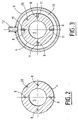
- Figures 2 and 3 are cross sections, respectively along lines II-II and III-III of Figure 1.
- FIG. 4 illustrates, diagrammatically in enlarged axial section, a preferred embodiment for the valve disposed at the proximal end of the device, in accordance with the invention.
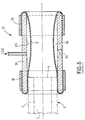
- Figure 5 shows, in schematic and partial perspective, the proximal end of the device according to the invention.
- Figure 6 schematically and partially illustrates an alternative embodiment of the respiratory device according to the present invention.
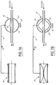
- FIGS. 7A and 7B schematically illustrate a device for controlling the closing and opening of the valves of FIGS. 4 and 6.
- a monolithic embodiment 1 of the device according to the invention can constitute, for example, an orotronal endotracheal tube with or without balloon, a pediatric endotracheal tube, a gas monitoring probe, an endobronchial probe, a nasopharyngeal probe, an anatomical intubation probe for children , a neonatal Cole probe, a Gedel cannula probe, a nasal oxygen therapy probe, a nasal or bucconasal mask or a nasal balloon for sleep apnea treatment.
- an orotronal endotracheal tube with or without balloon a pediatric endotracheal tube
- a gas monitoring probe an endobronchial probe
- a nasopharyngeal probe an anatomical intubation probe for children
- a neonatal Cole probe a Gedel cannula probe
- a nasal oxygen therapy probe a nasal or bucconasal mask or a nasal balloon for sleep apnea treatment.
- the device 1 comprises a tube 4, flexible or preformed (to adapt to the morphology of the patient) delimiting a main channel 5 opening, through the orifice 6, at the proximal end 2 and, through the orifice 7, at the distal end 3.
- the main channel 5 is capable of ensuring the passage between the orifices 6 and 7, one of which (the orifice 7) is intended to be located inside the respiratory tract of a patient, and the another (orifice 6) is intended to be outside of said patient.
- This orifice 6 can open into the open air and, in this case, the patient can breathe in fresh air and breathe out the stale air through the main channel 5.
- connect orifice 6 to a source of pressurized breathing gas and provide a system of one-way valves, so that the patient inhales breathing gas from said source through said main channel 5 and exhales the stale gas in the open air, also through this main channel.
- the diameter of the main channel 5 is of the order of a few millimeters. Satisfactory tests have been carried out with diameters of 3 mm, 7 mm, 8 mm and 12 mm.
- auxiliary channels 8 are provided, extending over almost entire length of the main channel 5. These auxiliary channels 8 are intended to be connected to a source of pressurized breathing gas. For example, this pressure is at most equal to 0.5 bar and it is adjustable.
- connection to the source of pressurized breathing gas can be achieved by means of a ring 9, sealingly surrounding the tube 4, on the side of the proximal end 2, and delimiting a sealed annular chamber 10 around said tube.
- the auxiliary channels 8 are placed in communication with the chamber 10, by means of local cut-outs 11 from the wall of the tube 4, and said chamber 10 is connected to said source of breathable gas by a conduit 12.
- the proximal ends of the channels 8 are closed, for example by plugs 13, introduced from the proximal end face 18 of the tube 4.
- the auxiliary channels 8 have a smaller diameter than that of the main channel 5.
- the diameter of the auxiliary channels 8 is preferably less than 1 mm and, advantageously, it is of the order of 400 to 800 microns.
- the auxiliary channels 8 open into a recess 14 in the internal wall 15 of the tube 4.
- the recess 14 is annular and centered on the axis 16 of the distal end 3. It has a face 14a, substantially transverse or slightly inclined so as to constitute a widening of the main channel 5, into which said auxiliary channels 8 open through their orifices 17, as well as a face 14b along the face 14a and converging in the direction of the axis 16.
- the internal wall 15 has a part 15a slightly flared towards the outside, as illustrated by the angle A in FIG. 1.
- auxiliary channels 8 are supplied with breathable gas under pressure through the elements 9 to 12, the corresponding gas jets strike the inclined face 14b, which deflects them in the direction of the axis 16 (arrows F in FIG. 1) , generating in the vicinity thereof a vacuum zone promoting gas circulation inside the main channel 5, from the proximal orifice to the distal orifice. This promotes the inspiration of the patient.
- the distance between each of the orifices 17 and the orifice 7 is of the order of 1 to 2 cm.
- At least one additional channel 20 is provided in the thickness of the tube 4 in order to open into 20A in the vicinity of the distal end 19 of the tube 4 and serve as a pressure tap.
- the supply and control device 22 is informed of the pressure prevailing in the patient's lungs via the link 22B.
- the device 22 can thus trigger an alarm and stop the insufflation of breathable gas through the connection 22A or the connection 22D.
- a calibrated exhaust valve 24 can be provided in the proximal end 2 of the tube 4, on the side opposite to the orifice 6 relative to the controlled valve 21.
- FIG. 4 schematically illustrates a preferred embodiment for said controlled valve 21.
- the controlled valve 21 includes a elastic inflatable bladder 25 with toroidal section, the external wall 25E of which bears against the internal wall 15 of the main channel 5 and which is connected to the connection 22C by a conduit 26.
- inflation gas is sent to said bladder 25 by the device 22 allows the internal wall 25I thereof to approach, so as to restrict or close off the main channel, while said bladder spontaneously retracts under the action of its own elasticity, when said inflation gas is evacuated from the bladder, by disengaging said main channel (in FIG. 4, the bladder 25 is shown in the middle position between opening and closing).
- the proximal annular face 18 delimiting the proximal orifice 6 of the tube 4 is provided with notches 27 allowing the communication of the main channel 5 with the outside, even if the orifice 6 is blocked by an object who accidentally leans on it.
- the tube 4 may comprise, at the distal end 3, an inflatable balloon (not shown) provided with the necessary safety devices or any other balloon making it possible to act as a safety valve in the event of overpressure in the lungs.
- This possible balloon can be inflated from an additional channel (not shown) associated with the tube 4.
- auxiliary channels 8 can be specialized for supplying a medical fluid.
- the auxiliary channels 8 are arranged regularly around the axis of the tube 4. Their number is variable depending on the use (adult or child), but it is generally between three and nine.
- the tube 4 of the device according to the invention can be made of any material already used in respiratory probes, for example in polyvinyl chloride, with a possible coating of silicone or steel allowing injections at high pressure.
- the dimensions of the device according to the invention can be very variable, essentially depending on the way in which the tube is placed and the size of the patient, who can be an adult, a child, an infant or a premature infant.
- FIG. 6 there is shown an alternative embodiment for using a commercial breathing tube 4.
- the controlled valve 21 is integral with a rigid tubular end piece 30 which can be fitted onto the proximal end 2 of said tube.
- the bladder 25 of FIG. 4 has been replaced by a portion of flexible and elastic tube 31, disposed inside the end piece 30 and folded at its ends on the external wall of the latter, where it is held by external rings 32.
- the inflation duct 22C opens into the cavity 33 formed between the internal wall 30I of the nozzle 30 and said portion 31 of flexible and elastic tube.
- a calibrated exhaust valve 34 is provided to optionally put the cavity 33 and the outside atmosphere into communication.
- the safety inflation device of the controlled valve 21 (FIG. 4 or FIG. 6), shown diagrammatically by FIGS. 7A and 7B, comprises a buffer capacity 40 connected to the bladder 25 or to the cavity 33 via a communication 41.
- the buffer capacity 40 is for example made up of a rigid outer envelope 42 and an inflatable inner envelope 43, delimiting between them a space 44 of variable volume. It is this variable volume space 44 which is connected to the bladder 25 or to the cavity 33 via the communication 41.
- the inflatable elastic inner envelope 43 is connected to the device 22.
- the controlled valve 21 can be connected to said device 22 by the link 22C (as described above) or by the link 22D (variant).
- a calibrated exhaust valve 45 is provided on the outer casing 42 to avoid any excess pressure in the space 44 with variable volume.
- the introduction and evacuation of the inflation gas from said controlled valve 21 results from the bidirectional movement in the communication 41 of the gas contained in the space 44 with variable value.
- the space 44 when the inner envelope 43 is deflated, has a volume equal to the internal volume of the bladder 25 or of the cavity 33, when the valve 21 is completely closed.
- inflation gas when inflation gas arrives in the interior envelope 43, it inflates and drives the gas from space 44 towards the bladder 25 or the cavity 33, through the communication 41 (see arrow f2) .
Landscapes
- Health & Medical Sciences (AREA)
- Heart & Thoracic Surgery (AREA)
- Life Sciences & Earth Sciences (AREA)
- Public Health (AREA)
- Anesthesiology (AREA)
- Biomedical Technology (AREA)
- Pulmonology (AREA)
- Hematology (AREA)
- Veterinary Medicine (AREA)
- Animal Behavior & Ethology (AREA)
- General Health & Medical Sciences (AREA)
- Engineering & Computer Science (AREA)
- Emergency Medicine (AREA)
- Respiratory Apparatuses And Protective Means (AREA)
- Accommodation For Nursing Or Treatment Tables (AREA)
- Massaging Devices (AREA)
- Medicines Containing Material From Animals Or Micro-Organisms (AREA)
- Media Introduction/Drainage Providing Device (AREA)
- Percussion Or Vibration Massage (AREA)
Abstract
Description
- La présente invention a pour objet un dispositif pour assistance respiratoire, utilisable sur des patients dont la respiration spontanée est absente ou insuffisante, qu'ils soient placés ou non sous respiration artificielle.
- On connaît divers dispositifs, tels que des masques, des sondes ou des canules orales, nasales, endotrachéales, trachéotomiques, destinés à faire la jonction entre un appareil de respiration artificielle et/ou d'anesthésie et le système respiratoire d'un patient. Ces dispositifs, essentiellement en forme de tubes, peuvent, selon le cas, comporter des moyens d'immobilisation tels que des pattes ou des collerettes au voisinage de l'extrémité proximale, pour le maintien sur la bouche ou le nez du patient, ou encore des ballonnets gonflables au voisinage de l'extrémité distale, pour le maintien par friction dans la trachée.
- Les dispositifs connus présentent des inconvénients importants. Ainsi, par exemple, lorsqu'un tube de type connu est déconnecté du respirateur artificiel et que le patient a besoin d'air enrichi en oxygène, il est nécessaire d'introduire dans ledit tube une sonde reliée à une source d'oxygène. Par ailleurs, dans les cas de respiration spontanée insuffisante, le patient doit nécessairement rester relié au respirateur jusqu'au rétablissement complet de sa respiration spontanée.
- Aussi, pour remédier à ces inconvénients, on a déjà proposé des dispositifs d'assistance respiratoire qui, outre le canal principal formé par le tube, comportent au moins un canal auxiliaire, par exemple ménagé dans la paroi dudit tube, permettant l'injection d'un jet de gaz respirable (oxygène, air ou mélange air-oxygène) destiné à la ventilation du patient, ce canal auxiliaire débouchant dans le canal principal au voisinage de l'extrémité distale de ce dernier.
- Toutefois, ces dispositifs d'assistance respiratoire à canal auxiliaire d'injection de gaz respiratoire présentent l'inconvénient que ledit jet de gaz respirable doit être à une pression élevée, ce qui, d'une part, risque de traumatiser la muqueuse du patient qu'elle frappe et, d'autre part, rend difficile, sinon impossible, l'humidification dudit gaz respirable. On sait en effet qu'un jet gazeux est d'autant plus difficile à humidifier que sa pression est plus élevée. Or, il est important que le jet de gaz respirable soit humidifié afin d'éviter le dessèchement de la muqueuse du patient.
- La présente invention a pour objet principal de remédier à cet inconvénient.
- A cette fin, selon l'invention, le dispositif d'assistance respiratoire comportant un tube qui forme un canal principal et qui est destiné à être relié par son extrémité distale à une voie respiratoire d'un patient pour que ledit canal principal relie, à l'extérieur, le système respiratoire dudit patient, ledit dispositif comportant de plus au moins un canal auxiliaire permettant l'injection d'un jet gazeux respirable dans ledit système respiratoire et débouchant dans ledit canal principal au voisinage de l'extrémité distale de ce dernier, est remarquable en ce qu'il comporte une vanne commandée susceptible d'obturer au moins partiellement l'extrémité proximale dudit canal principal, au moins pendant l'insufflation dudit jet gazeux.
- Ainsi, du fait que ladite extrémité proximale du canal principal est au moins partiellement obturée pendant l'insufflation du jet gazeux respirable, la pression de celui-ci peut être abaissée (puisque la fuite de gaz vers l'extérieur est empêchée ou, pour le moins, réduite) pour un effet de ventilation semblable. L'abaissement de la pression du gaz de ventilation permet alors l'humidification aisée dudit gaz, par exemple par barbotage ou bien par pulvérisation.
- Bien entendu, ledit jet gazeux respirable peut, de façon connue, être continuel ou impulsionnel. Si ledit jet gazeux est continuel, ladite vanne commandée doit, d'une part, fermer partiellement ou totalement l'extrémité proximale dudit canal principal pendant l'inspiration du patient, afin d'obtenir l'abaissement de pression précité et, d'autre part, ouvrir partiellement ou totalement ladite extrémité proximale pendant l'expiration dudit patient. L'ouverture partielle de cette extrémité proximale pendant l'expiration du patient peut être utilisée comme "frein expiratoire" permettant d'obliger ledit patient à des exercices bénéfiques de respiration. Si, en revanche, ledit jet gazeux est impulsionnel, ladite vanne commandée doit, d'une part, fermer partiellement ou totalement l'extrémité proximale dudit canal principal pendant les impulsions du jet gazeux, à la même fin d'abaissement de pression que précédemment, et, d'autre part, ouvrir partiellement ou totalement ladite extrémité proximale entre lesdites impulsions du jet gazeux. Entre ces impulsions, il est bien entendu possible de se servir de l'ouverture partielle de ladite vanne commandée pour obtenir un "frein expiratoire".
- On remarquera que l'on peut même utiliser le dispositif conforme à l'invention sans insufflation de gaz respirable, le patient inspirant et expirant à travers ledit canal et ladite vanne commandée, qui commande alors la section de passage dudit canal.
- Ladite vanne commandée peut former un ensemble monolithique avec ledit tube ou bien elle peut être rapportée à celui-ci. Dans ce dernier cas, qui permet de transformer des tubes respiratoires normaux en tubes respiratoires conformes à la présente invention, il est avantageux que ladite vanne commandée soit solidaire d'un embout susceptible d'être emboîté sur l'extrémité proximale dudit tube.
- La vanne commandée peut être de toute réalisation connue, avec commande électrique, pneumatique, etc ... Cependant, il est avantageux qu'elle permette, en position ouverte, de conserver au canal principal un diamètre intérieur suffisant pour permettre le passage à travers ledit canal des instruments et des sondes médicales que l'opérateur veut utiliser, sans interrompre la ventilation.
- Aussi, dans un mode de réalisation préféré, ladite vanne commandée comporte une enceinte étanche à section toroïdale, disposée au voisinage de l'extrémité proximale dudit canal principal et comportant au moins une paroi interne souple et élastique qui, en se dilatant ou en se rétractant en réponse à l'introduction ou à l'évacuation d'un gaz de gonflage dans ladite enceinte étanche, commande la section de passage dudit canal principal. On remarquera qu'une telle vanne, même lorsqu'elle est complètement fermée, permet le passage d'instruments ou de sondes dans ledit canal par l'écartement forcé de ladite paroi interne souple.
- Afin d'éviter qu'un objet appliqué par inadvertance contre l'orifice proximal dudit tube obture ledit canal principal et empêche l'expiration du patient, le bord libre de l'extrémité proximale dudit tube comporte au moins une échancrure.
- Egalement à des fins de sécurité, le dispositif conforme à la présente invention comporte de plus des moyens recevant la pression du côté de l'extrémité distale dudit tube et susceptibles d'imposer l'ouverture à ladite vanne commandée pour dégager ledit canal principal. Pour augmenter encore la sécurité, on peut prévoir une vanne d'échappement tarée disposée à l'extrémité proximale dudit tube, du côté opposé au bord libre de l'extrémité proximale par rapport à ladite vanne commandée.
- Pour augmenter encore plus la sécurité, on peut faire en sorte que l'introduction et l'évacuation du gaz de gonflage de ladite enceinte étanche résulte du déplacement bidirectionnel d'un volume de gaz approprié, contenu dans une capacité tampon à volume variable commandable.
- Par ailleurs, pour éviter que le jet de gaz respirable humidifié vienne frapper directement la muqueuse, risquant par son énergie cinétique de traumatiser la muqueuse, il est avantageux que, comme cela a été décrit dans le brevet européen EP-A-0 390 684, au moins l'extrémité distale dudit canal auxiliaire débouchant dans le canal principal soit parallèle à celui-ci et que, en regard de l'orifice distal dudit canal auxiliaire, soient prévus des moyens de déflexion dudit jet de gaz respirable de ventilation vers l'intérieur dudit canal principal.
- Ainsi, le jet de gaz respirable humidifié sous faible pression traversant ledit canal auxiliaire est défléchi vers l'axe du canal principal, lorsqu'il pénètre dans celui-ci. En aval desdits moyens de déflexion, c'est-à-dire à l'intérieur du canal principal, la pression dudit jet de gaz respirable chute et le jet sort à encore plus faible pression à travers l'orifice distal du tube. L'expérience a montré qu'en aval de la sortie distale du tube, la pression est faible et maintenue constante dans tout l'espace respiratoire. Cette pression est dépendante du débit de gaz respirable dans les canaux auxiliaires. Par suite, avec le dispositif d'assistance respiratoire conforme à l'invention, on peut par exemple apporter de l'oxygène humide ou un mélange air-oxygène humide directement dans les poumons, à hauteur de la carène, et supprimer ainsi l'espace mort qui existe dans les sondes actuelles et qui est d'environ un tiers du volume respiratoire total pour un adulte et d'environ la moitié pour les nouveaux-nés prématurés.
- La suppression de cet espace mort correspond à une augmentation de performance du cycle respiratoire de plus de 25% dans tous les cas de malades et de près de 50% dans certains cas.
- Lorsque le dispositif selon l'invention comporte une pluralité de canaux auxiliaires, il est avantageux qu'au moins certains d'entre eux soient alimentés en commun en gaz respirable. Une telle alimentation en commun desdits canaux peut se faire par l'intermédiaire d'une bague de distribution, coaxiale audit tube. Par ailleurs, lesdits canaux auxiliaires non alimentés en commun peuvent servir à l'introduction de produits gazeux additionnels, tels que des produits médicamenteux.
- Ainsi, on voit que le dispositif conforme à l'invention permet :
- l'humidification du gaz respirable insufflé,
- l'intubation de longue durée de l'assistance respiratoire sans assèchement,
- l'injection de médicaments ou d'anesthésiques pendant l'assistance respiratoire,
- la mesure dynamique des pressions, car il suffit de prévoir des canaux auxiliaires auxquels sont associées des sondes appropriées,
- l'établissement d'un microdébit de gaz respirable dans les canaux auxiliaires pour éviter l'obstruction desdits canaux par des mucosités ;
- l'augmentation du volume échangé, car la pression est auto-limitée et il n'y a aucun risque d'écrasement des capillaires pulmonaires,
- la diminution pour une même quantité d'oxygène échangée de l'importance d'oxygène dans le mélange, ce qui diminue d'autant les effets secondaires de l'assistance,
- la possibilité d'utiliser des respirateurs moins coûteux que les respirateurs actuels.
- Les figures du dessin annexé feront bien comprendre comment l'invention peut être réalisée. Sur ces figures, des références identiques désignent des éléments semblables.
- La figure 1 est une vue schématique et partielle, en coupe axiale agrandie, d'un mode de réalisation du dispositif de l'invention.
- Les figures 2 et 3 sont des coupes transversales, respectivement selon les lignes II-II et III-III de la figure 1.
- La figure 4 illustre, schématiquement en coupe axiale agrandie, un mode de réalisation préféré pour la vanne disposée à l'extrémité proximale du dispositif, conformément à l'invention.
- La figure 5 montre, en perspective schématique et partielle, l'extrémité proximale du dispositif conforme à l'invention.
- La figure 6 illustre schématiquement et partiellement une variante de réalisation du dispositif respiratoire conforme à la présente invention.
- Les figures 7A et 7B illustrent schématiquement un dispositif de commande de la fermeture et de l'ouverture des vannes des figures 4 et 6.
- Sur la figure 1, on a représenté, schématiquement et à grande échelle, les seules extrémités proximale 2 et distale 3 d'un mode de réalisation monolithique 1 du dispositif selon l'invention. Ce mode de réalisation monolithique peut constituer, par exemple, une sonde endotrachéale oro-nasale avec ou sans ballonnet, une sonde endotrachéale pédiatrique, une sonde de monitorage des gaz, une sonde endobronchique, une sonde nasopharyngée, une sonde d'intubation anatomique pour enfant, une sonde de Cole néonatale, une sonde canule de Gedel, une sonde nasale d'oxygénothérapie, un masque nasal ou bucconasal ou un ballon nasal pour traitement d'apnée du sommeil.
- Le dispositif 1 comporte un tube 4, souple ou préformé (pour s'adapter à la morphologie du patient) délimitant un canal principal 5 débouchant, par l'orifice 6, à l'extrémité proximale 2 et, par l'orifice 7, à l'extrémité distale 3.
- Ainsi, le canal principal 5 est capable d'assurer le passage entre les orifices 6 et 7, dont l'un (l'orifice 7) est destiné à se trouver à l'intérieur des voies respiratoires d'un patient, et l'autre (l'orifice 6) est destiné à se trouver à l'extérieur dudit patient. Cet orifice 6 peut déboucher à l'air libre et, dans ce cas, le patient peut inspirer de l'air frais et expirer l'air vicié à travers le canal principal 5. On peut également, comme cela est expliqué ci-après, relier l'orifice 6 à une source de gaz respirable sous pression et prévoir un système de valves unidirectionnelles, pour que le patient inspire le gaz respirable de ladite source à travers ledit canal principal 5 et expire le gaz vicié à l'air libre, également à travers ce canal principal.
- Le diamètre du canal principal 5 est de l'ordre de quelques millimètres. Des essais satisfaisants ont été effectués avec des diamètres de 3 mm, 7 mm, 8 mm et 12 mm.
- Par ailleurs, dans l'épaisseur de la paroi du tube 4, sont ménagés des canaux auxiliaires 8, s'étendant sur la presque totalité de la longueur du canal principal 5. Ces canaux auxiliaires 8 sont destinés à être reliés à une source de gaz respirable sous pression. Par exemple, cette pression est au plus égale à 0,5 bar et elle est réglable.
- Comme cela est représenté sur les figures 1 et 3, la liaison à la source de gaz respirable sous pression peut être réalisée au moyen d'une bague 9, entourant de façon étanche le tube 4, du côté de l'extrémité proximale 2, et délimitant une chambre annulaire étanche 10 autour dudit tube. Les canaux auxiliaires 8 sont mis en communication avec la chambre 10, grâce à des arrachements locaux 11 de la paroi du tube 4, et ladite chambre 10 est reliée à ladite source de gaz respirable par un conduit 12. Bien entendu, les extrémités proximales des canaux 8 sont obturées, par exemple par des bouchons 13, introduits à partir de la face d'extrémité proximale 18 du tube 4.
- Les canaux auxiliaires 8 ont un diamètre plus petit que celui du canal principal 5. Le diamètre des canaux auxiliaires 8 est de préférence inférieur à 1 mm et, de façon avantageuse, il est de l'ordre de 400 à 800 microns. Du côté distal, les canaux auxiliaires 8 débouchent dans un évidement 14 de la paroi interne 15 du tube 4. L'évidement 14 est annulaire et centré sur l'axe 16 de l'extrémité distale 3. Il comporte une face 14a, sensiblement transversale ou légèrement inclinée de façon à constituer un évasement du canal principal 5, dans laquelle débouchent lesdits canaux auxiliaires 8 par leurs orifices 17, ainsi qu'une face 14b suivant la face 14a et convergeant en direction de l'axe 16.
- De préférence, entre la face inclinée convergente 14b et l'orifice distal 7, la paroi interne 15 présente une partie 15a légèrement évasée vers l'extérieur, comme cela est illustré par l'angle A sur la figure 1.
- Ainsi, lorsque les canaux auxiliaires 8 sont alimentés en gaz respirable sous pression à travers les éléments 9 à 12, les jets gazeux correspondants heurtent la face inclinée 14b, qui les défléchit en direction de l'axe 16 (flèches F sur la figure 1), engendrant au voisinage de celui-ci une zone de dépression favorisant la circulation gazeuse à l'intérieur du canal principal 5, de l'orifice proximal vers l'orifice distal. On favorise ainsi l'inspiration du patient.
- De préférence, la distance entre chacun des orifices 17 et l'orifice 7 est de l'ordre de 1 à 2 cm.
- Au moins un canal supplémentaire 20 est prévu dans l'épaisseur du tube 4 afin de déboucher en 20A au voisinage de l'extrémité distale 19 du tube 4 et servir de prise de pression.
- Le dispositif 1 comporte de plus une vanne commandée 21 susceptible d'obturer au moins partiellement l'extrémité proximale 2 du canal principal 5 pendant l'insufflation dudit jet gazeux, ainsi qu'un dispositif d'alimentation et de commande 22. Ce dernier dispositif 22 est relié :
- à l'extrémité proximale 2 du tube 4, par une liaison 22A,
- au canal supplémentaire 20, par une liaison 22B,
- à la vanne commandée 21, par une liaison 22C, et
- au conduit 12, par une liaison 22D sur laquelle est intercalé un humidificateur 23.
- Les modes de fonctionnement du dispositif selon l'invention sont les suivants :
- dans le mode de respiration artificielle, le dispositif 22 coupe la liaison 22D, commande la vanne 21 à l'ouverture au moins partielle par la liaison 22C et adresse du gaz respirable dans le tube 4 par l'intermédiaire de la liaison 22A ;
- dans le mode d'assistance respiratoire, le dispositif 22 coupe la liaison 22A pour mettre l'orifice 6 en communication avec l'atmosphère, commande la vanne 21 alternativement à l'ouverture et à la fermeture par la liaison 22C et adresse un jet, continuel ou impulsionnel, de gaz respirable aux canaux auxiliaires 8 par la liaison 22D, à travers l'humidificateur 23. Dans ce mode d'assistance respiratoire, la vanne 21 est fermée, partiellement ou totalement, pendant l'insufflation de gaz respirable dans le patient à travers les canaux 8 et ouverte au moins partiellement pendant l'expiration dudit patient à travers le tube 4, vers l'extérieur. Du fait que l'extrémité proximale 2 du tube 4 est obturée pendant l'insufflation de gaz respirable, la pression de celui-ci peut être faible, ce qui permet de l'humidifier facilement dans l'humidificateur 23.
- Dans les deux modes de fonctionnement, le dispositif d'alimentation et de commande 22 est informé de la pression régnant dans les poumons du patient par l'intermédiaire de la liaison 22B. Dans le cas d'une surpression anormale, le dispositif 22 peut ainsi déclencher une alarme et arrêter l'insufflation de gaz respirable à travers la liaison 22A ou la liaison 22D.
- Pour augmenter encore la sécurité, une vanne d'échappement tarée 24 peut être prévue dans l'extrémité proximale 2 du tube 4, du côté opposé à l'orifice 6 par rapport à la vanne commandée 21. Ainsi, en cas de surpression accidentelle, une fuite de gaz se produit à l'extérieur du patient, à travers la paroi du tube 4, pour éliminer instantanément cette surpression.
- Sur la figure 4, on a illustré schématiquement un mode de réalisation préféré pour ladite vanne commandée 21. Dans ce mode de réalisation, la vanne commandée 21 comporte une vessie gonflable élastique 25 à section toroïdale, dont la paroi externe 25E prend appui contre la paroi interne 15 du canal principal 5 et qui est reliée à la liaison 22C par un conduit 26. Ainsi, du gaz de gonflage adressé à ladite vessie 25 par le dispositif 22 permet à la paroi interne 25I de celle-ci de se rapprocher, de façon à restreindre ou obturer le canal principal, tandis que ladite vessie se rétracte spontanément sous l'action de sa propre élasticité, lorsque ledit gaz de gonflage est évacué de la vessie, en dégageant ledit canal principal (sur la figure 4, la vessie 25 est représentée en position moyenne entre l'ouverture et la fermeture).
- Lorsque cette vanne 21 est en position ouverte, la paroi interne 25I de la vessie 25 est écartée et ménage suffisamment de place pour passer des appareils médicaux et chirurgicaux à travers le tube 4. On remarquera que, même en position fermée, de tels appareils médicaux et chirurgicaux peuvent être passés de force à travers la vanne 21, grâce à l'élasticité de la paroi interne 25I.
- Comme le montre la figure 5, la face annulaire proximale 18 délimitant l'orifice proximal 6 du tube 4 est pourvue d'échancrures 27 permettant la communication du canal principal 5 avec l'extérieur, même si l'orifice 6 est bouché par un objet qui s'y appuie accidentellement.
- De ce qui précède, on voit donc que, grâce à l'invention, on obtient une assistance respiratoire humidifiée non agressive pour le patient, avec disparition quasiment totale de l'espace mort inhérent aux sondes connues.
- Le tube 4 peut comporter, à l'extrémité distale 3, un ballonnet gonflable (non représenté) muni des dispositifs nécessaires de sécurité ou tout autre ballonnet permettant de se comporter comme une soupape de sécurité en cas de surpression dans les poumons. Cet éventuel ballonnet peut être gonflé à partir d'un canal supplémentaire (non représenté) associé au tube 4.
- De plus, un au moins des canaux auxiliaires 8 peut être spécialisé pour apporter un fluide médical.
- Comme le montrent les figures 2 et 3, les canaux auxiliaires 8 sont disposés régulièrement autour de l'axe du tube 4. Leur nombre est variable suivant les utilisations (adulte ou enfant), mais il est généralement compris entre trois et neuf.
- Le tube 4 du dispositif selon l'invention peut être réalisé en toute matière déjà utilisée dans les sondes respiratoires, par exemple en un chlorure de polyvinyle, avec un éventuel revêtement de silicone ou en acier permettant les injections à pression élevée.
- Bien entendu, les dimensions du dispositif selon l'invention peuvent être très variables, essentiellement en fonction de la voie de mise en place du tube et de la taille du patient, qui peut être un adulte, un enfant, un nourrisson ou un prématuré.
- Sur la figure 6, on a représenté une variante de réalisation permettant d'utiliser un tube respiratoire 4 du commerce. Dans ce mode de réalisation, la vanne commandée 21 est solidaire d'un embout tubulaire rigide 30 pouvant être emboîté sur l'extrémité proximale 2 dudit tube. Dans l'exemple représenté sur la figure 6, la vessie 25 de la figure 4 a été remplacée par une portion de tube souple et élastique 31, disposée à l'intérieur de l'embout 30 et repliée à ses extrémités sur la paroi externe de celui-ci, où elle est maintenue par des bagues externes 32. Le conduit de gonflage 22C débouche dans la cavité 33 formée entre la paroi interne 30I de l'embout 30 et ladite portion 31 de tube souple et élastique. On comprendra aisément que la vanne de la figure 6 fonctionne de façon identique à celle de la figure 4. Une vanne d'échappement tarée 34 est prévue pour éventuellement mettre en communication la cavité 33 et l'atmosphère extérieure.
- Le dispositif de gonflage de sécurité de la vanne commandée 21 (figure 4 ou figure 6), montré schématiquement par les figures 7A et 7B, comporte une capacité tampon 40 reliée à la vessie 25 ou à la cavité 33 par l'intermédiaire d'une communication 41.
- La capacité tampon 40 est par exemple constituée d'une enveloppe extérieure rigide 42 et d'une enveloppe intérieure gonflable 43, délimitant entre elles un espace 44 à volume variable. C'est cet espace à volume variable 44 qui est relié à la vessie 25 ou à la cavité 33 par l'intermédiaire de la communication 41. De plus, l'enveloppe intérieure élastique gonflable 43 est reliée au dispositif 22. Comme représenté sur les figures 7A et 7B, la vanne commandée 21 peut être reliée audit dispositif 22 par la liaison 22C (comme décrit précédemment) ou par la liaison 22D (variante).
- Une vanne d'échappement tarée 45 est prévue sur l'enveloppe extérieure 42 pour éviter toute surpression dans l'espace 44 à volume variable.
- Ainsi, l'introduction et l'évacuation du gaz de gonflage de ladite vanne commandée 21 résulte du déplacement bidirectionnel dans la communication 41 du gaz contenu dans l'espace 44 à valeur variable. Par exemple, l'espace 44, lorsque l'enveloppe intérieure 43 est dégonflée, a un volume égal au volume interne de la vessie 25 ou de la cavité 33, lorsque la vanne 21 est totalement fermée.
- Lorsqu'aucun gaz de gonflage n'est adressé à la capacité tampon 40 (figure 7A), l'enveloppe intérieure 43 est dégonflée et l'élasticité de la vessie 25 ou de la paroi 31 de la vanne 21 chasse le gaz contenu dans celle-ci (voir la flèche f1) dans l'espace à volume variable 44, à travers la communication 41. La vanne 21 est alors en position ouverte.
- En revanche, lorsque du gaz de gonflage arrive dans l'enveloppe intérieure 43, celle-ci se gonfle et chasse le gaz de l'espace 44 vers la vessie 25 ou la cavité 33, à travers la communication 41 (voir la flèche f2).
Claims (12)
- Dispositif d'assistance respiratoire comportant un tube (4) qui forme un canal principal (5) et qui est destiné à être relié par son extrémité distale (3) à une voie respiratoire d'un patient pour que ledit canal principal (5) relie, à l'extérieur, le système respiratoire dudit patient, ledit dispositif comportant de plus au moins un canal auxiliaire (8) permettant d'insuffler un jet gazeux respirable dans ledit système respiratoire et débouchant dans ledit canal principal (5) au voisinage de l'extrémité distale (7) de ce dernier,
caractérisé en ce qu'il comporte une vanne commandée (21) susceptible d'obturer au moins partiellement l'extrémité proximale dudit canal principal (5), au moins pendant l'insufflation dudit jet gazeux. - Dispositif selon la revendication 1,
caractérisé en ce que ladite vanne commandée (21) forme un ensemble monolithique avec ledit tube (4). - Dispositif selon la revendication 1,
caractérisé en ce que ladite vanne commandée (21) est rapportée sur ledit tube (4). - Dispositif selon la revendication 3,
caractérisé en ce que ladite vanne commandée (21) est solidaire d'un embout (30) susceptible d'être emboîté sur l'extrémité proximale (2) dudit tube (4). - Dispositif selon l'une des revendications 1 à 4,
caractérisé en ce que ladite vanne commandée (21) comporte une enceinte étanche (25) à section toroïdale, disposée au voisinage de l'extrémité proximale dudit canal principal (5) et comportant au moins une paroi interne souple et élastique (25I) qui, en se dilatant ou en se rétractant en réponse à l'introduction ou à l'évacuation d'un gaz de gonflage dans ladite enceinte étanche, commande la section de passage dudit canal principal (5). - Dispositif selon l'une des revendications 1 à 5,
caractérisé en ce que le bord libre (18) de l'extrémité proximale dudit tube (4) comporte au moins une échancrure (27). - Dispositif selon l'une des revendications 1 à 6,
caractérisé en ce qu'il comporte au moins une prise de pression (20, 20A), disposée du côté de l'extrémité distale (3) dudit tube (4). - Dispositif selon la revendication 7,
caractérisé en ce que ladite prise de pression est formée par l'orifice (20A) par lequel un canal auxiliaire (20), ménagé dans ladite paroi dudit tube (4), débouche au voisinage de l'extrémité distale (19) dudit tube. - Dispositif selon l'une des revendications 7 ou 8,
caractérisé en ce qu'il comporte des moyens (22) recevant la pression prélevée par ladite prise de pression (20A) et susceptibles d'imposer l'ouverture à ladite vanne commandée (21) pour dégager ledit canal principal (5). - Dispositif selon l'une des revendications 1 à 9,
caractérisé en ce qu'il comporte une vanne d'échappement tarée (24), disposée à l'extrémité proximale dudit tube (4), du côté opposé au bord libre (18) de l'extrémité proximale (2) par rapport à ladite vanne commandée (21). - Dispositif selon l'une des revendications 5 à 10,
caractérisé en ce que l'introduction et l'évacuation du gaz de gonflage de ladite enceinte étanche résulte du déplacement bidirectionnel d'un volume de gaz approprié contenu dans une capacité tampon à volume variable commandable. - Dispositif selon l'une des revendications 1 à 10,
caractérisé en ce qu'au moins l'extrémité distale dudit canal auxiliaire (8) débouchant dans le canal principal (5) est parallèle à celui-ci et en ce que, en regard de l'orifice distal (17) dudit canal auxiliaire (8), sont prévus des moyens (14b) de déflexion dudit jet de gaz respirable de ventilation vers l'intérieur dudit canal principal (5).
Applications Claiming Priority (2)
| Application Number | Priority Date | Filing Date | Title |
|---|---|---|---|
| FR9411062 | 1994-09-14 | ||
| FR9411062A FR2724564B1 (fr) | 1994-09-16 | 1994-09-16 | Dispositif d'assistance respiratoire |
Publications (2)
| Publication Number | Publication Date |
|---|---|
| EP0701834A1 true EP0701834A1 (fr) | 1996-03-20 |
| EP0701834B1 EP0701834B1 (fr) | 1999-10-27 |
Family
ID=9466995
Family Applications (1)
| Application Number | Title | Priority Date | Filing Date |
|---|---|---|---|
| EP95402014A Expired - Lifetime EP0701834B1 (fr) | 1994-09-16 | 1995-09-06 | Dispositif d'assistance respiratoire |
Country Status (6)
| Country | Link |
|---|---|
| US (1) | US5538002A (fr) |
| EP (1) | EP0701834B1 (fr) |
| AT (1) | ATE185978T1 (fr) |
| DE (1) | DE69512985T2 (fr) |
| ES (1) | ES2138712T3 (fr) |
| FR (1) | FR2724564B1 (fr) |
Cited By (14)
| Publication number | Priority date | Publication date | Assignee | Title |
|---|---|---|---|---|
| GB2320731A (en) * | 1996-04-01 | 1998-07-01 | Baker Hughes Inc | Downhole flow control devices |
| EP0911051A1 (fr) * | 1997-10-27 | 1999-04-28 | Georges Boussignac | Dispositif d'assistance respiratoire |
| EP0978291A1 (fr) | 1998-08-05 | 2000-02-09 | Georges Boussignac | Dispositif pour assistance respiratoire |
| EP0983772A1 (fr) * | 1998-09-03 | 2000-03-08 | Georges Boussignac | Dispositif pour assistance respiratoire |
| FR2813197A1 (fr) | 2000-08-22 | 2002-03-01 | Georges Boussignac | Dispositif d'assistance respiratoire avec des administration de produits nebulises |
| FR2831824A1 (fr) | 2001-11-06 | 2003-05-09 | Georges Boussignac | Dispositif pour assistance respiratoire |
| FR2912660A1 (fr) * | 2007-02-15 | 2008-08-22 | Georges Boussignac | Dispositif de respiration artificielle pour une personne en etat d'arret cardiaque. |
| WO2012104517A1 (fr) * | 2011-02-03 | 2012-08-09 | Georges Boussignac | Dispositif de respiration artificielle pour la réanimation d'une personne en état d'arrêt cardiaque |
| WO2015189525A1 (fr) | 2014-06-13 | 2015-12-17 | Vygon | Dispositif d'assistance respiratoire, appareil nasal et masque d'assistance respiratoire |
| CN113768583A (zh) * | 2016-04-06 | 2021-12-10 | 沃克血管有限公司 | 用于吸入血栓的系统 |
| US12150659B2 (en) | 2014-05-19 | 2024-11-26 | Walk Vascular, Llc | Systems and methods for removal of blood and thrombotic material |
| US12171445B2 (en) | 2021-02-15 | 2024-12-24 | Walk Vascular, Llc | Systems and methods for removal of blood and thrombotic material |
| US12329406B2 (en) | 2008-10-13 | 2025-06-17 | Walk Vascular, Llc | Assisted aspiration catheter system |
| US12369940B2 (en) | 2007-02-05 | 2025-07-29 | Walk Vascular, Llc | Thrombectomy apparatus and method |
Families Citing this family (64)
| Publication number | Priority date | Publication date | Assignee | Title |
|---|---|---|---|---|
| US6371114B1 (en) * | 1998-07-24 | 2002-04-16 | Minnesota Innovative Technologies & Instruments Corporation | Control device for supplying supplemental respiratory oxygen |
| DE19840760C2 (de) * | 1998-09-07 | 2000-07-20 | Map Medizintechnik Gmbh | Schalldämpfer für Beatmungsvorrichtung |
| US6390094B1 (en) | 1998-10-02 | 2002-05-21 | Henry Slionski | Device of regulating air flow through an endotracheal tube |
| US6102042A (en) | 1998-12-22 | 2000-08-15 | Respironics, Inc. | Insufflation system, attachment and method |
| US7431031B2 (en) * | 1998-12-22 | 2008-10-07 | Ric Investments, Llc | Insufflation system and method |
| DE29909671U1 (de) * | 1999-06-02 | 1999-09-02 | Dräger Medizintechnik GmbH, 23558 Lübeck | Kupplung für ein Beatmungsschlauch-System |
| AU778777B2 (en) * | 1999-09-23 | 2004-12-23 | Fisher & Paykel Healthcare Limited | Breathing assistance apparatus |
| US7063086B2 (en) * | 1999-09-23 | 2006-06-20 | Fisher & Paykel Healthcare Limited | Breathing assistance apparatus |
| WO2001076658A2 (fr) | 2000-04-05 | 2001-10-18 | Deroyal Industries, Inc. | Systeme d'administration d'oxygene pour des nouveau-nes |
| EP1161963B1 (fr) * | 2000-06-06 | 2005-01-19 | Jakob Bösherz | Respirateur |
| GB2368531A (en) * | 2000-10-31 | 2002-05-08 | Paul Fenton | Anaesthesia breathing apparatus |
| DE10226783A1 (de) * | 2002-06-15 | 2004-01-08 | Gottlieb Weinmann Geräte für Medizin und Arbeitsschutz GmbH & Co. | Verfahren zur Steuerung eines Beatmungsgerätes sowie Vorrichtung zur Beatmung mit Steuerung |
| US20040089305A1 (en) * | 2002-11-13 | 2004-05-13 | Vallarta John-Eric S. | Endotracheal tube safety device connector |
| US7588033B2 (en) | 2003-06-18 | 2009-09-15 | Breathe Technologies, Inc. | Methods, systems and devices for improving ventilation in a lung area |
| US8381729B2 (en) | 2003-06-18 | 2013-02-26 | Breathe Technologies, Inc. | Methods and devices for minimally invasive respiratory support |
| US7406966B2 (en) | 2003-08-18 | 2008-08-05 | Menlo Lifesciences, Llc | Method and device for non-invasive ventilation with nasal interface |
| DE102005045663A1 (de) * | 2005-09-13 | 2007-03-22 | Novalung Gmbh | Vorrichtung zur Unterbrechung eines durch einen Hohlkörper fließenden Blutstroms in einem extrakorporalen Blutkreislauf |
| CN101454041B (zh) | 2005-09-20 | 2012-12-12 | 呼吸科技公司 | 对患者进行呼吸支持的系统、方法和装置 |
| FR2899483B1 (fr) * | 2006-04-06 | 2008-05-30 | Georges Boussignac | Dispositif de respiration artificielle pour patients atteints d'hypoxemie ou d'anoxemie |
| EP2023987B1 (fr) | 2006-05-18 | 2016-11-09 | Breathe Technologies, Inc. | Espaceur de trachéostome |
| US20080029173A1 (en) * | 2006-08-07 | 2008-02-07 | Diperna Paul Mario | Variable flow reshapable flow restrictor apparatus and related methods |
| WO2008144589A1 (fr) | 2007-05-18 | 2008-11-27 | Breathe Technologies, Inc. | Procédés et dispositifs pour détecter la respiration et fournir une thérapie de ventilation |
| CA2700878C (fr) | 2007-09-26 | 2018-07-24 | Breathe Technologies, Inc. | Procedes et dispositifs permettant d'assister le flux d'inspiration et d'expiration dans une therapie par ventilation |
| CN101888868B (zh) | 2007-09-26 | 2014-01-22 | 呼吸科技公司 | 用于治疗睡眠呼吸暂停的方法和设备 |
| WO2009151791A2 (fr) | 2008-04-18 | 2009-12-17 | Breathe Technologies, Inc. | Procédés et dispositifs pour détecter la respiration et réguler des fonctions respiratoires |
| WO2009129506A1 (fr) | 2008-04-18 | 2009-10-22 | Breathe Technologies, Inc. | Procédés et dispositifs pour détecter la respiration et commander des fonctions d’insufflateur |
| CN102196837B (zh) | 2008-08-22 | 2015-09-09 | 呼吸科技公司 | 利用开放的气道界面提供机械通气的方法和装置 |
| US10252020B2 (en) | 2008-10-01 | 2019-04-09 | Breathe Technologies, Inc. | Ventilator with biofeedback monitoring and control for improving patient activity and health |
| US10695519B2 (en) | 2009-04-02 | 2020-06-30 | Breathe Technologies, Inc. | Methods, systems and devices for non-invasive open ventilation with gas delivery nozzles within nasal pillows |
| US9132250B2 (en) | 2009-09-03 | 2015-09-15 | Breathe Technologies, Inc. | Methods, systems and devices for non-invasive ventilation including a non-sealing ventilation interface with an entrainment port and/or pressure feature |
| US9962512B2 (en) | 2009-04-02 | 2018-05-08 | Breathe Technologies, Inc. | Methods, systems and devices for non-invasive ventilation including a non-sealing ventilation interface with a free space nozzle feature |
| EP2724739B1 (fr) | 2009-07-30 | 2015-07-01 | Tandem Diabetes Care, Inc. | Système de pompe à perfusion ambulatoire |
| CA2774902C (fr) | 2009-09-03 | 2017-01-03 | Breathe Technologies, Inc. | Procedes, systemes et dispositifs de ventilation non invasive comprenant une interface de ventilation non etanche avec orifice d'entrainement et/ou element de pression |
| US8893716B2 (en) * | 2009-10-20 | 2014-11-25 | Mercury Enterprises, Inc. | Disposable breathing assistance device with manometer |
| GB201006480D0 (en) | 2010-04-19 | 2010-06-02 | Intersurgical Ag | Improvements relating to respiratory apparatus |
| AU2011292111B2 (en) | 2010-08-16 | 2015-03-26 | Breathe Technologies, Inc. | Methods, systems and devices using LOX to provide ventilatory support |
| US8939152B2 (en) | 2010-09-30 | 2015-01-27 | Breathe Technologies, Inc. | Methods, systems and devices for humidifying a respiratory tract |
| US9180242B2 (en) | 2012-05-17 | 2015-11-10 | Tandem Diabetes Care, Inc. | Methods and devices for multiple fluid transfer |
| US9370635B2 (en) | 2012-08-23 | 2016-06-21 | Mercury Enterprises, Inc. | Optimized breathing assistance device |
| US9173998B2 (en) | 2013-03-14 | 2015-11-03 | Tandem Diabetes Care, Inc. | System and method for detecting occlusions in an infusion pump |
| US10350137B2 (en) | 2014-02-19 | 2019-07-16 | Keith G. Lurie | Elevation timing systems and methods for head up CPR |
| US9750661B2 (en) | 2014-02-19 | 2017-09-05 | Keith G. Lurie | Systems and methods for head up cardiopulmonary resuscitation |
| US11259988B2 (en) | 2014-02-19 | 2022-03-01 | Keith G. Lurie | Active compression decompression and upper body elevation system |
| US12144777B2 (en) | 2014-02-19 | 2024-11-19 | Resuscitation Innovations Llc | Methods and systems to reduce brain damage |
| US11246794B2 (en) | 2014-02-19 | 2022-02-15 | Keith G. Lurie | Systems and methods for improved post-resuscitation recovery |
| US10667987B2 (en) | 2014-02-19 | 2020-06-02 | Keith G. Lurie | Uniform chest compression CPR |
| US10245209B2 (en) | 2014-02-19 | 2019-04-02 | Keith G. Lurie | Systems and methods for gravity-assisted cardiopulmonary resuscitation |
| US11096861B2 (en) | 2014-02-19 | 2021-08-24 | Keith G. Lurie | Systems and methods for gravity-assisted cardiopulmonary resuscitation and defibrillation |
| US9707152B2 (en) | 2014-02-19 | 2017-07-18 | Keith G. Lurie | Systems and methods for head up cardiopulmonary resuscitation |
| US11020314B2 (en) | 2014-02-19 | 2021-06-01 | Keith G. Lurie | Methods and systems to reduce brain damage |
| US11844742B2 (en) | 2014-02-19 | 2023-12-19 | Keith G. Lurie | Methods and systems to reduce brain damage |
| US9801782B2 (en) | 2014-02-19 | 2017-10-31 | Keith G. Lurie | Support devices for head up cardiopulmonary resuscitation |
| US10406068B2 (en) | 2014-02-19 | 2019-09-10 | Keith G. Lurie | Lockable head up cardiopulmonary resuscitation support device |
| US10406069B2 (en) | 2014-02-19 | 2019-09-10 | Keith G. Lurie | Device for elevating the head and chest for treating low blood flow states |
| US9433427B2 (en) | 2014-04-08 | 2016-09-06 | Incuvate, Llc | Systems and methods for management of thrombosis |
| CA2996690A1 (fr) * | 2015-08-27 | 2017-03-02 | Avent, Inc. | Dispositif de regulation de debit d'ecoulement variable |
| US10561440B2 (en) | 2015-09-03 | 2020-02-18 | Vesatek, Llc | Systems and methods for manipulating medical devices |
| US20170100142A1 (en) | 2015-10-09 | 2017-04-13 | Incuvate, Llc | Systems and methods for management of thrombosis |
| WO2017205824A1 (fr) * | 2016-05-27 | 2017-11-30 | Proveris Scientific Corporation | Dispositifs et procédés d'utilisation de dispositifs d'administration de médicament |
| US10792449B2 (en) | 2017-10-03 | 2020-10-06 | Breathe Technologies, Inc. | Patient interface with integrated jet pump |
| US11678905B2 (en) | 2018-07-19 | 2023-06-20 | Walk Vascular, Llc | Systems and methods for removal of blood and thrombotic material |
| US12274458B2 (en) | 2021-02-15 | 2025-04-15 | Walk Vascular, Llc | Systems and methods for removal of blood and thrombotic material |
| US11806455B2 (en) * | 2021-09-15 | 2023-11-07 | Bellco S.R.L. | Fluid conduit system |
| CN116672555B (zh) * | 2022-01-18 | 2025-08-01 | 河北金康安医疗器械科技有限公司 | 咳痰机的气路切换装置及咳痰系统 |
Citations (7)
| Publication number | Priority date | Publication date | Assignee | Title |
|---|---|---|---|---|
| US3717174A (en) * | 1971-08-03 | 1973-02-20 | R Dewall | Perfusion safety valve |
| EP0042321A1 (fr) * | 1980-06-10 | 1981-12-23 | L'air Liquide, Societe Anonyme Pour L'etude Et L'exploitation Des Procedes Georges Claude | Respirateur à correction automatique de ventilation |
| EP0390684A1 (fr) | 1989-03-31 | 1990-10-03 | Georges Boussignac | Dispositif d'assistance respiratoire |
| US5050593A (en) * | 1990-06-01 | 1991-09-24 | Massachusetts Institute Of Technology | Respirator triggering mechanism |
| US5161773A (en) * | 1990-08-01 | 1992-11-10 | Numed, Inc. | Method and apparatus for controlling fluid flow |
| US5186431A (en) * | 1989-09-22 | 1993-02-16 | Yehuda Tamari | Pressure sensitive valves for extracorporeal circuits |
| WO1993021982A1 (fr) * | 1992-05-07 | 1993-11-11 | New York University | Traitement de l'apnee par ventilation spontanee avec pression expiratoire positive ajustable |
Family Cites Families (59)
| Publication number | Priority date | Publication date | Assignee | Title |
|---|---|---|---|---|
| DE160709C (fr) * | ||||
| US2791217A (en) * | 1955-05-19 | 1957-05-07 | Edward G Iskander | Valvular apparatus for use in surgery |
| US3173418A (en) * | 1961-01-10 | 1965-03-16 | Ostap E Baran | Double-wall endotracheal cuff |
| US3211152A (en) * | 1961-11-15 | 1965-10-12 | Ernest A Stern | Safety endotracheal tube cuff |
| US3437747A (en) * | 1964-03-24 | 1969-04-08 | Sheldon Edward E | Devices for inspection using fiberoptic members |
| DK111149B (da) * | 1966-06-16 | 1968-06-17 | V Lomholt | Respirationskateter. |
| GB1171439A (en) * | 1967-04-10 | 1969-11-19 | Jorge Alberto Millet Puig | Improvements in an Endotracheal Tube |
| US3707151A (en) * | 1971-02-16 | 1972-12-26 | Richard Robert Jackson | Self-inflating endotracheal tube |
| US3821570A (en) * | 1972-09-11 | 1974-06-28 | Phelon Co Inc | Generator and triggering device for electronic ignition system |
| US3821510A (en) * | 1973-02-22 | 1974-06-28 | H Muncheryan | Hand held laser instrumentation device |
| GB1447987A (en) * | 1973-03-10 | 1976-09-02 | Carden E | Ventilating device for use in anesthesiology |
| US3859995A (en) * | 1973-07-02 | 1975-01-14 | Westinghouse Electric Corp | Breathing assist apparatus |
| DE2353153C3 (de) * | 1973-10-23 | 1978-10-05 | Robert G. Dr. Pittsburgh Pa. Carroll (V.St.A.) | Beatmungsrohr |
| US3991764A (en) * | 1973-11-28 | 1976-11-16 | Purdue Research Foundation | Plasma arc scalpel |
| US3915173A (en) * | 1974-07-08 | 1975-10-28 | Ansur Inc | Intubation device for the inhalation of gasses |
| US3982541A (en) * | 1974-07-29 | 1976-09-28 | Esperance Jr Francis A L | Eye surgical instrument |
| US4176662A (en) * | 1977-06-17 | 1979-12-04 | The United States Of America As Represented By The Administrator Of The National Aeronautics And Space Administration | Apparatus for endoscopic examination |
| US4183102A (en) * | 1977-09-08 | 1980-01-15 | Jacques Guiset | Inflatable prosthetic device for lining a body duct |
| DE2828447C2 (de) * | 1978-06-29 | 1980-05-14 | Willy Ruesch Gmbh & Co Kg, 7053 Kernen | Laryngealtubus |
| DE2831313A1 (de) * | 1978-07-17 | 1980-02-07 | Draegerwerk Ag | Geraet zur unterstuetzung der atmung und/oder kuenstlichen beatmung |
| US4299237A (en) * | 1978-07-21 | 1981-11-10 | Foti Thomas M | Closed flow caloric test device |
| DE2847681C2 (de) * | 1978-11-03 | 1983-01-05 | Drägerwerk AG, 2400 Lübeck | Trachealtubus |
| IL58185A (en) * | 1979-09-05 | 1982-07-30 | Northwind Ltd | Artificial respiration device |
| US4418688A (en) * | 1981-07-06 | 1983-12-06 | Laserscope, Inc. | Microcatheter having directable laser and expandable walls |
| US4584998A (en) * | 1981-09-11 | 1986-04-29 | Mallinckrodt, Inc. | Multi-purpose tracheal tube |
| US4470407A (en) * | 1982-03-11 | 1984-09-11 | Laserscope, Inc. | Endoscopic device |
| US4423725A (en) * | 1982-03-31 | 1984-01-03 | Baran Ostap E | Multiple surgical cuff |
| DE3212097C2 (de) * | 1982-04-01 | 1985-10-03 | Drägerwerk AG, 2400 Lübeck | Beatmungsgerät mit einer über ein Steuergerät steuerbaren Atemgasquelle |
| US4471775A (en) * | 1982-09-07 | 1984-09-18 | Clair Michael W | Endotracheal tube cuff synchronizing system |
| DE3381238D1 (de) * | 1982-10-08 | 1990-04-05 | David Hardcastle | Ballon-katheter und verfahren fuer dessen herstellung. |
| US4488548A (en) * | 1982-12-22 | 1984-12-18 | Sherwood Medical Company | Endotracheal tube assembly |
| US4526196A (en) * | 1983-01-26 | 1985-07-02 | Nayan S. Shah | Gas pressure measuring and regulating device and method |
| US4581017B1 (en) * | 1983-03-07 | 1994-05-17 | Bard Inc C R | Catheter systems |
| DE3313855C1 (de) * | 1983-04-16 | 1984-03-15 | Drägerwerk AG, 2400 Lübeck | Beatmungssystem |
| DE3325797A1 (de) * | 1983-07-16 | 1985-01-31 | Natec Inst Naturwiss | Ballonkatheter, insbesondere endotrachealkatheter |
| JPH0221041Y2 (fr) * | 1983-11-08 | 1990-06-07 | ||
| DE3401924C2 (de) * | 1984-01-20 | 1986-04-24 | Drägerwerk AG, 2400 Lübeck | Zuführungsstück für die Atemgase bei der Hochfrequenzbeatmung |
| BE898753A (fr) * | 1984-01-25 | 1984-05-16 | Laserscope Inc | Procede pour amener un liquide porteur d'oxygene dans un vaisseau sanguin au cours d'un acte medical |
| CA1254474A (fr) * | 1984-02-21 | 1989-05-23 | Seymour W. Shapiro | Sondes endotracheales |
| US4552142A (en) * | 1984-05-10 | 1985-11-12 | Ohio Medical Research, Inc. | Ventilator system having a control valve in the ventilator circuit |
| US4592353A (en) * | 1984-05-22 | 1986-06-03 | Surgical Laser Technologies Ohio, Inc. | Medical and surgical laser probe |
| DE3442736C2 (de) * | 1984-11-23 | 1987-03-05 | Tassilo Dr.med. 7800 Freiburg Bonzel | Dilatationskatheter |
| US4657014A (en) * | 1985-03-11 | 1987-04-14 | Shiley, Inc. | Liquid interface fiberoptic coupler |
| US4649914A (en) * | 1985-11-12 | 1987-03-17 | Kowalewski Ryszard J | Rapid self-inflating tracheal tube with constant pressure control feature |
| JPS62186872A (ja) * | 1986-02-14 | 1987-08-15 | 鳥取大学長 | 呼吸圧重畳式カフ圧調整装置 |
| US4694828A (en) * | 1986-04-21 | 1987-09-22 | Eichenbaum Daniel M | Laser system for intraocular tissue removal |
| FR2597744A1 (fr) * | 1986-04-29 | 1987-10-30 | Boussignac Georges | Catheter cardio-vasculaire pour tir au rayon laser |
| ATE61525T1 (de) * | 1986-04-29 | 1991-03-15 | Georges Boussignac | Kanuele zur unterstuetzung der beatmung. |
| DE3621350A1 (de) * | 1986-06-26 | 1988-01-14 | Bonzel Tassilo | Dilatationskatheter mit einem aufweitbaren ballon |
| US4821714A (en) * | 1986-12-04 | 1989-04-18 | Smelser Danny N | Pharmaceutical endotracheal tube |
| US4739756A (en) * | 1986-12-19 | 1988-04-26 | Horn Sherman W | Endotracheal tube |
| FR2613639A1 (fr) * | 1987-04-10 | 1988-10-14 | Reclus Edouard | Dispositif pour pulser et pulveriser, avec des gaz, des produits ou des melanges |
| US4872483A (en) * | 1987-12-31 | 1989-10-10 | International Medical Products, Inc. | Conveniently hand held self-contained electronic manometer and pressure modulating device |
| FR2626476B1 (fr) * | 1988-02-01 | 1997-10-17 | Boussignac Georges | Sonde destinee a etre introduite a l'interieur d'un corps vivant |
| US4976261A (en) * | 1989-04-03 | 1990-12-11 | Advanced Pulmonary Technologies, Inc. | Endotracheal tube with inflatable cuffs |
| US5235973A (en) * | 1991-05-15 | 1993-08-17 | Gary Levinson | Tracheal tube cuff inflation control and monitoring system |
| US5318021A (en) * | 1991-06-05 | 1994-06-07 | Alessi David M | Endotracheal tube with automatic cuff inflation and deflation |
| US5421325A (en) * | 1992-04-30 | 1995-06-06 | Cinberg; James Z. | Endotracheal tube assembly and related method |
| US5304135A (en) * | 1992-08-13 | 1994-04-19 | Cordis Corporation | Axial multi-chamber angioplasty balloon assembly |
-
1994
- 1994-09-16 FR FR9411062A patent/FR2724564B1/fr not_active Expired - Fee Related
- 1994-10-20 US US08/326,256 patent/US5538002A/en not_active Expired - Lifetime
-
1995
- 1995-09-06 AT AT95402014T patent/ATE185978T1/de active
- 1995-09-06 ES ES95402014T patent/ES2138712T3/es not_active Expired - Lifetime
- 1995-09-06 DE DE69512985T patent/DE69512985T2/de not_active Expired - Lifetime
- 1995-09-06 EP EP95402014A patent/EP0701834B1/fr not_active Expired - Lifetime
Patent Citations (7)
| Publication number | Priority date | Publication date | Assignee | Title |
|---|---|---|---|---|
| US3717174A (en) * | 1971-08-03 | 1973-02-20 | R Dewall | Perfusion safety valve |
| EP0042321A1 (fr) * | 1980-06-10 | 1981-12-23 | L'air Liquide, Societe Anonyme Pour L'etude Et L'exploitation Des Procedes Georges Claude | Respirateur à correction automatique de ventilation |
| EP0390684A1 (fr) | 1989-03-31 | 1990-10-03 | Georges Boussignac | Dispositif d'assistance respiratoire |
| US5186431A (en) * | 1989-09-22 | 1993-02-16 | Yehuda Tamari | Pressure sensitive valves for extracorporeal circuits |
| US5050593A (en) * | 1990-06-01 | 1991-09-24 | Massachusetts Institute Of Technology | Respirator triggering mechanism |
| US5161773A (en) * | 1990-08-01 | 1992-11-10 | Numed, Inc. | Method and apparatus for controlling fluid flow |
| WO1993021982A1 (fr) * | 1992-05-07 | 1993-11-11 | New York University | Traitement de l'apnee par ventilation spontanee avec pression expiratoire positive ajustable |
Cited By (31)
| Publication number | Priority date | Publication date | Assignee | Title |
|---|---|---|---|---|
| GB2320731A (en) * | 1996-04-01 | 1998-07-01 | Baker Hughes Inc | Downhole flow control devices |
| US6484800B2 (en) | 1996-04-01 | 2002-11-26 | Baker Hughes Incorporated | Downhole flow control devices |
| US6334486B1 (en) | 1996-04-01 | 2002-01-01 | Baker Hughes Incorporated | Downhole flow control devices |
| US6450255B2 (en) | 1996-04-01 | 2002-09-17 | Baker Hughes Incorporated | Downhole flow control devices |
| WO1997037102A3 (fr) * | 1996-04-01 | 2000-01-20 | Baker Hughes Inc | Dispositifs de regulation d'ecoulement de fond de puits |
| GB2320731B (en) * | 1996-04-01 | 2000-10-25 | Baker Hughes Inc | Downhole flow control devices |
| US6612547B2 (en) | 1996-04-01 | 2003-09-02 | Baker Hughes Incorporated | Downhole flow control devices |
| WO1999021603A1 (fr) * | 1997-10-27 | 1999-05-06 | Georges Boussignac | Dispositif d'assistance respiratoire |
| US6273087B1 (en) | 1997-10-27 | 2001-08-14 | Georges Boussignac | Respiratory aid |
| FR2770137A1 (fr) * | 1997-10-27 | 1999-04-30 | Georges Boussignac | Dispositif d'assistance respiratoire |
| EP0911051A1 (fr) * | 1997-10-27 | 1999-04-28 | Georges Boussignac | Dispositif d'assistance respiratoire |
| FR2782012A1 (fr) * | 1998-08-05 | 2000-02-11 | Georges Boussignac | Dispositif pour assistance respiratoire |
| EP0978291A1 (fr) | 1998-08-05 | 2000-02-09 | Georges Boussignac | Dispositif pour assistance respiratoire |
| EP0983772A1 (fr) * | 1998-09-03 | 2000-03-08 | Georges Boussignac | Dispositif pour assistance respiratoire |
| FR2782925A1 (fr) * | 1998-09-03 | 2000-03-10 | Georges Boussignac | Dispositif pour assistance respiratoire |
| FR2813197A1 (fr) | 2000-08-22 | 2002-03-01 | Georges Boussignac | Dispositif d'assistance respiratoire avec des administration de produits nebulises |
| FR2831824A1 (fr) | 2001-11-06 | 2003-05-09 | Georges Boussignac | Dispositif pour assistance respiratoire |
| WO2003039638A1 (fr) | 2001-11-06 | 2003-05-15 | Georges Boussignac | Dispositif pour assistance respiratoire |
| US12369940B2 (en) | 2007-02-05 | 2025-07-29 | Walk Vascular, Llc | Thrombectomy apparatus and method |
| FR2912660A1 (fr) * | 2007-02-15 | 2008-08-22 | Georges Boussignac | Dispositif de respiration artificielle pour une personne en etat d'arret cardiaque. |
| WO2008113913A3 (fr) * | 2007-02-15 | 2008-11-13 | Georges Boussignac | Procédé et dispositif pour la réanimation d'une personne en état d'arrêt cardiaque. |
| US12329406B2 (en) | 2008-10-13 | 2025-06-17 | Walk Vascular, Llc | Assisted aspiration catheter system |
| WO2012104517A1 (fr) * | 2011-02-03 | 2012-08-09 | Georges Boussignac | Dispositif de respiration artificielle pour la réanimation d'une personne en état d'arrêt cardiaque |
| FR2971162A1 (fr) * | 2011-02-03 | 2012-08-10 | Georges Boussignac | Dispositif de respiration artificielle pour la reanimation d'une personne en etat d'arret cardiaque |
| US10195382B2 (en) | 2011-02-03 | 2019-02-05 | Georges Boussignac | Artificial respiration device for resuscitating a person in a state of cardiac arrest |
| US12150659B2 (en) | 2014-05-19 | 2024-11-26 | Walk Vascular, Llc | Systems and methods for removal of blood and thrombotic material |
| US12156665B2 (en) | 2014-05-19 | 2024-12-03 | Walk Vascular, Llc | Systems and methods for removal of blood and thrombotic material |
| US10806888B2 (en) | 2014-06-13 | 2020-10-20 | Vygon | Respiratory assistance device, nasal apparatus and respiratory assistance mask |
| WO2015189525A1 (fr) | 2014-06-13 | 2015-12-17 | Vygon | Dispositif d'assistance respiratoire, appareil nasal et masque d'assistance respiratoire |
| CN113768583A (zh) * | 2016-04-06 | 2021-12-10 | 沃克血管有限公司 | 用于吸入血栓的系统 |
| US12171445B2 (en) | 2021-02-15 | 2024-12-24 | Walk Vascular, Llc | Systems and methods for removal of blood and thrombotic material |
Also Published As
| Publication number | Publication date |
|---|---|
| DE69512985D1 (de) | 1999-12-02 |
| FR2724564A1 (fr) | 1996-03-22 |
| FR2724564B1 (fr) | 1997-04-04 |
| ES2138712T3 (es) | 2000-01-16 |
| EP0701834B1 (fr) | 1999-10-27 |
| US5538002A (en) | 1996-07-23 |
| DE69512985T2 (de) | 2000-04-20 |
| ATE185978T1 (de) | 1999-11-15 |
Similar Documents
| Publication | Publication Date | Title |
|---|---|---|
| EP0701834B1 (fr) | Dispositif d'assistance respiratoire | |
| EP0978291B1 (fr) | Dispositif pour assistance respiratoire | |
| CA2030546C (fr) | Dispositif d'assistance respiratoire | |
| EP1340515B1 (fr) | Dispositif d'assistance respiratoire | |
| EP1441791B1 (fr) | Dispositif pour assistance respiratoire | |
| EP0983772B1 (fr) | Dispositif pour assistance respiratoire | |
| EP0245142B1 (fr) | Tube pour assistance respiratoire | |
| CA2695570C (fr) | Dispositif d'assistance respiratoire | |
| EP3154615B1 (fr) | Dispositif d'assistance respiratoire, appareil nasal et masque d'assistance respiratoire | |
| EP0640355A1 (fr) | Tube d'assistance respiratoire | |
| EP2239004B1 (fr) | Dispositif d'assistance respiratoire et système de mesure comportant un tel dispositif | |
| EP2890438B1 (fr) | Dispositif d'assistance respiratoire, appareil nasal et masque d'assistance respiratoire | |
| FR2973708A1 (fr) | Dispositif d'assistance respiratoire | |
| FR2921840A1 (fr) | Dispositif d'assistance respiratoire | |
| FR2813197A1 (fr) | Dispositif d'assistance respiratoire avec des administration de produits nebulises | |
| FR2980978A1 (fr) | Dispositif de respiration artificielle pour la reanimation d'une personne en etat d'arret cardiaque. |
Legal Events
| Date | Code | Title | Description |
|---|---|---|---|
| PUAI | Public reference made under article 153(3) epc to a published international application that has entered the european phase |
Free format text: ORIGINAL CODE: 0009012 |
|
| AK | Designated contracting states |
Kind code of ref document: A1 Designated state(s): AT BE CH DE DK ES GB GR IE IT LI LU MC NL PT SE |
|
| 17P | Request for examination filed |
Effective date: 19960422 |
|
| GRAG | Despatch of communication of intention to grant |
Free format text: ORIGINAL CODE: EPIDOS AGRA |
|
| 17Q | First examination report despatched |
Effective date: 19981214 |
|
| GRAG | Despatch of communication of intention to grant |
Free format text: ORIGINAL CODE: EPIDOS AGRA |
|
| GRAH | Despatch of communication of intention to grant a patent |
Free format text: ORIGINAL CODE: EPIDOS IGRA |
|
| GRAH | Despatch of communication of intention to grant a patent |
Free format text: ORIGINAL CODE: EPIDOS IGRA |
|
| GRAA | (expected) grant |
Free format text: ORIGINAL CODE: 0009210 |
|
| AK | Designated contracting states |
Kind code of ref document: B1 Designated state(s): AT BE CH DE DK ES GB GR IE IT LI LU MC NL PT SE |
|
| PG25 | Lapsed in a contracting state [announced via postgrant information from national office to epo] |
Ref country code: NL Free format text: LAPSE BECAUSE OF FAILURE TO SUBMIT A TRANSLATION OF THE DESCRIPTION OR TO PAY THE FEE WITHIN THE PRESCRIBED TIME-LIMIT Effective date: 19991027 Ref country code: GR Free format text: LAPSE BECAUSE OF NON-PAYMENT OF DUE FEES Effective date: 19991027 Ref country code: AT Free format text: LAPSE BECAUSE OF FAILURE TO SUBMIT A TRANSLATION OF THE DESCRIPTION OR TO PAY THE FEE WITHIN THE PRESCRIBED TIME-LIMIT Effective date: 19991027 |
|
| REF | Corresponds to: |
Ref document number: 185978 Country of ref document: AT Date of ref document: 19991115 Kind code of ref document: T |
|
| REG | Reference to a national code |
Ref country code: CH Ref legal event code: EP |
|
| GBT | Gb: translation of ep patent filed (gb section 77(6)(a)/1977) |
Effective date: 19991027 |
|
| REF | Corresponds to: |
Ref document number: 69512985 Country of ref document: DE Date of ref document: 19991202 |
|
| REG | Reference to a national code |
Ref country code: ES Ref legal event code: FG2A Ref document number: 2138712 Country of ref document: ES Kind code of ref document: T3 |
|
| ITF | It: translation for a ep patent filed | ||
| REG | Reference to a national code |
Ref country code: IE Ref legal event code: FG4D Free format text: FRENCH |
|
| PG25 | Lapsed in a contracting state [announced via postgrant information from national office to epo] |
Ref country code: PT Free format text: LAPSE BECAUSE OF FAILURE TO SUBMIT A TRANSLATION OF THE DESCRIPTION OR TO PAY THE FEE WITHIN THE PRESCRIBED TIME-LIMIT Effective date: 20000127 Ref country code: DK Free format text: LAPSE BECAUSE OF FAILURE TO SUBMIT A TRANSLATION OF THE DESCRIPTION OR TO PAY THE FEE WITHIN THE PRESCRIBED TIME-LIMIT Effective date: 20000127 |
|
| NLV1 | Nl: lapsed or annulled due to failure to fulfill the requirements of art. 29p and 29m of the patents act | ||
| PG25 | Lapsed in a contracting state [announced via postgrant information from national office to epo] |
Ref country code: IE Free format text: LAPSE BECAUSE OF NON-PAYMENT OF DUE FEES Effective date: 20000720 |
|
| REG | Reference to a national code |
Ref country code: IE Ref legal event code: FD4D |
|
| PLBE | No opposition filed within time limit |
Free format text: ORIGINAL CODE: 0009261 |
|
| STAA | Information on the status of an ep patent application or granted ep patent |
Free format text: STATUS: NO OPPOSITION FILED WITHIN TIME LIMIT |
|
| PGFP | Annual fee paid to national office [announced via postgrant information from national office to epo] |
Ref country code: SE Payment date: 20000828 Year of fee payment: 6 |
|
| PG25 | Lapsed in a contracting state [announced via postgrant information from national office to epo] |
Ref country code: LU Free format text: LAPSE BECAUSE OF NON-PAYMENT OF DUE FEES Effective date: 20000906 |
|
| PGFP | Annual fee paid to national office [announced via postgrant information from national office to epo] |
Ref country code: GB Payment date: 20000906 Year of fee payment: 6 |
|
| PGFP | Annual fee paid to national office [announced via postgrant information from national office to epo] |
Ref country code: ES Payment date: 20000914 Year of fee payment: 6 |
|
| PG25 | Lapsed in a contracting state [announced via postgrant information from national office to epo] |
Ref country code: MC Free format text: THE PATENT HAS BEEN ANNULLED BY A DECISION OF A NATIONAL AUTHORITY Effective date: 20000930 Ref country code: LI Free format text: LAPSE BECAUSE OF NON-PAYMENT OF DUE FEES Effective date: 20000930 Ref country code: CH Free format text: LAPSE BECAUSE OF NON-PAYMENT OF DUE FEES Effective date: 20000930 Ref country code: BE Free format text: LAPSE BECAUSE OF NON-PAYMENT OF DUE FEES Effective date: 20000930 |
|
| 26N | No opposition filed | ||
| BERE | Be: lapsed |
Owner name: LABRUNE JEAN-CLAUDE Effective date: 20000930 Owner name: BOUSSIGNAC GEORGES Effective date: 20000930 |
|
| REG | Reference to a national code |
Ref country code: CH Ref legal event code: PL |
|
| PG25 | Lapsed in a contracting state [announced via postgrant information from national office to epo] |
Ref country code: GB Free format text: LAPSE BECAUSE OF NON-PAYMENT OF DUE FEES Effective date: 20010906 |
|
| PG25 | Lapsed in a contracting state [announced via postgrant information from national office to epo] |
Ref country code: SE Free format text: LAPSE BECAUSE OF NON-PAYMENT OF DUE FEES Effective date: 20010907 Ref country code: ES Free format text: LAPSE BECAUSE OF NON-PAYMENT OF DUE FEES Effective date: 20010907 |
|
| EUG | Se: european patent has lapsed |
Ref document number: 95402014.5 |
|
| REG | Reference to a national code |
Ref country code: ES Ref legal event code: FD2A Effective date: 20021011 |
|
| PG25 | Lapsed in a contracting state [announced via postgrant information from national office to epo] |
Ref country code: IT Free format text: LAPSE BECAUSE OF NON-PAYMENT OF DUE FEES Effective date: 20050906 |
|
| PG25 | Lapsed in a contracting state [announced via postgrant information from national office to epo] |
Ref country code: DE Free format text: LAPSE BECAUSE OF NON-PAYMENT OF DUE FEES Effective date: 20100401 |
|
| REG | Reference to a national code |
Ref country code: DE Ref legal event code: R073 Ref document number: 69512985 Country of ref document: DE |
|
| REG | Reference to a national code |
Ref country code: DE Ref legal event code: R074 Ref document number: 69512985 Country of ref document: DE Ref country code: DE Ref legal event code: R073 Ref document number: 69512985 Country of ref document: DE |
|
| REG | Reference to a national code |
Ref country code: DE Ref legal event code: R074 Ref document number: 69512985 Country of ref document: DE Effective date: 20111215 Ref country code: DE Ref legal event code: R074 Ref document number: 69512985 Country of ref document: DE Effective date: 20111212 |
|
| REG | Reference to a national code |
Ref country code: DE Ref legal event code: R119 Ref document number: 69512985 Country of ref document: DE Effective date: 20130403 |
|
| PG25 | Lapsed in a contracting state [announced via postgrant information from national office to epo] |
Ref country code: DE Free format text: LAPSE BECAUSE OF NON-PAYMENT OF DUE FEES Effective date: 20130403 |
|
| PGFP | Annual fee paid to national office [announced via postgrant information from national office to epo] |
Ref country code: DE Payment date: 20100910 Year of fee payment: 16 |