EP0701879B1 - Dispositif de montage - Google Patents
Dispositif de montage Download PDFInfo
- Publication number
- EP0701879B1 EP0701879B1 EP95114086A EP95114086A EP0701879B1 EP 0701879 B1 EP0701879 B1 EP 0701879B1 EP 95114086 A EP95114086 A EP 95114086A EP 95114086 A EP95114086 A EP 95114086A EP 0701879 B1 EP0701879 B1 EP 0701879B1
- Authority
- EP
- European Patent Office
- Prior art keywords
- mounting bracket
- assembling device
- tool
- machining
- piston rod
- Prior art date
- Legal status (The legal status is an assumption and is not a legal conclusion. Google has not performed a legal analysis and makes no representation as to the accuracy of the status listed.)
- Expired - Lifetime
Links
Images



Classifications
-
- B—PERFORMING OPERATIONS; TRANSPORTING
- B25—HAND TOOLS; PORTABLE POWER-DRIVEN TOOLS; MANIPULATORS
- B25B—TOOLS OR BENCH DEVICES NOT OTHERWISE PROVIDED FOR, FOR FASTENING, CONNECTING, DISENGAGING, OR HOLDING
- B25B27/00—Hand tools, specially adapted for fitting together or separating parts or objects whether or not involving some deformation, not otherwise provided for
- B25B27/02—Hand tools, specially adapted for fitting together or separating parts or objects whether or not involving some deformation, not otherwise provided for for connecting objects by press fit or detaching same
- B25B27/026—Hand tools, specially adapted for fitting together or separating parts or objects whether or not involving some deformation, not otherwise provided for for connecting objects by press fit or detaching same fluid driven
-
- B—PERFORMING OPERATIONS; TRANSPORTING
- B23—MACHINE TOOLS; METAL-WORKING NOT OTHERWISE PROVIDED FOR
- B23P—METAL-WORKING NOT OTHERWISE PROVIDED FOR; COMBINED OPERATIONS; UNIVERSAL MACHINE TOOLS
- B23P19/00—Machines for simply fitting together or separating metal parts or objects, or metal and non-metal parts, whether or not involving some deformation; Tools or devices therefor so far as not provided for in other classes
-
- B—PERFORMING OPERATIONS; TRANSPORTING
- B23—MACHINE TOOLS; METAL-WORKING NOT OTHERWISE PROVIDED FOR
- B23Q—DETAILS, COMPONENTS, OR ACCESSORIES FOR MACHINE TOOLS, e.g. ARRANGEMENTS FOR COPYING OR CONTROLLING; MACHINE TOOLS IN GENERAL CHARACTERISED BY THE CONSTRUCTION OF PARTICULAR DETAILS OR COMPONENTS; COMBINATIONS OR ASSOCIATIONS OF METAL-WORKING MACHINES, NOT DIRECTED TO A PARTICULAR RESULT
- B23Q1/00—Members which are comprised in the general build-up of a form of machine, particularly relatively large fixed members
- B23Q1/25—Movable or adjustable work or tool supports
- B23Q1/44—Movable or adjustable work or tool supports using particular mechanisms
- B23Q1/56—Movable or adjustable work or tool supports using particular mechanisms with sliding pairs only, the sliding pairs being the first two elements of the mechanism
- B23Q1/58—Movable or adjustable work or tool supports using particular mechanisms with sliding pairs only, the sliding pairs being the first two elements of the mechanism a single sliding pair
-
- B—PERFORMING OPERATIONS; TRANSPORTING
- B23—MACHINE TOOLS; METAL-WORKING NOT OTHERWISE PROVIDED FOR
- B23Q—DETAILS, COMPONENTS, OR ACCESSORIES FOR MACHINE TOOLS, e.g. ARRANGEMENTS FOR COPYING OR CONTROLLING; MACHINE TOOLS IN GENERAL CHARACTERISED BY THE CONSTRUCTION OF PARTICULAR DETAILS OR COMPONENTS; COMBINATIONS OR ASSOCIATIONS OF METAL-WORKING MACHINES, NOT DIRECTED TO A PARTICULAR RESULT
- B23Q7/00—Arrangements for handling work specially combined with or arranged in, or specially adapted for use in connection with, machine tools, e.g. for conveying, loading, positioning, discharging, sorting
- B23Q7/14—Arrangements for handling work specially combined with or arranged in, or specially adapted for use in connection with, machine tools, e.g. for conveying, loading, positioning, discharging, sorting co-ordinated in production lines
- B23Q7/1426—Arrangements for handling work specially combined with or arranged in, or specially adapted for use in connection with, machine tools, e.g. for conveying, loading, positioning, discharging, sorting co-ordinated in production lines with work holders not rigidly fixed to the transport devices
Definitions
- the invention relates to an assembly device for machining workpieces Work tables or pallets, with a support element that is supported by a mounting bracket and with a tool holder for various tools.
- the invention has for its object to provide an assembly device for use various tools is suitable, which allows a quick replacement or implementation of the Tools allowed and the work piece to be machined automatically in the Adjusts height.
- the processing operations primarily relate to pressing, drilling, Milling, surface treatment, but also on inspection processes.
- the advantage of the invention is that various tools can be used quickly and that the height of the work elements on the respective workpiece itself aligns.
- the assembly device is equipped with a mounting bracket 2, which is used to hold and Force application of the processing element 4 and support element 5 is used.
- the mounting bracket 2 is U-shaped, so that the machining and Support elements are inserted and attached.
- the U-shaped Mounting bracket 2 on the two opposite sides of the U with a variety of mounting holes 3 as close as possible. These fit perfectly opposite bores 3 can be connected by fastening bolts 7.
- the Elements 4 and 5 are correspondingly with the same holes in the area of their respective Insert into the U-shaped mounting bracket 2. With it any Set the distances between elements 4 and 5 and elements 4 and 5 can be also vary in height above the processing table surface.
- elements 4 and 5 can be implemented, i.e. by repenting everyone Element can then be processed in the interior of the workpiece.
- the decisive factor here is that the mounting bracket 2 alone for the application of force is decisive and that the forces applied between elements 4 and 5 for Machining of the workpiece can only be carried by the mounting bracket that is created accordingly.
- This total suspension is gem. 3 is further improved by a linear guide 11.
- the entire device 1 is supported by a base plate 12. On this base plate 12 is vertically attached a stand 13 which serves as a carrier of the mounting device 1.
- the linear guide 11 is effective between the stand 13 and the mounting bracket 2.
- An the stand 13 rollers 15 are attached in pairs at a predetermined distance, so that a slide rail 16 can be guided between the rollers.
- This slide rail 16 is The edges are almost double T-shaped and in the area of the roller guide rounded this adjusted.
- the slide rail 16 is with the bottom 14 of the Mounting bracket 2 screwed over holes 6.
- the stand 13 is assigned a cylinder 17 and fixed at its lower end with the Stand 13 connected to receptacle 18.
- the cylinder 17 acts in the longitudinal direction of the Stand 13, so vertical.
- the piston rod 19 of the cylinder 17 is over a Driver 20 firmly connected to the mounting bracket 2.
- the cylinder 17 with pressure acted upon, so the piston rod 19 and the driver 20 also the Mounting bracket 2.
- This mounting bracket 2 is in the Linear guide performed by the slide rail 16 slides in the rollers 15.
- the pressure to be applied in the cylinder 17 only has to be so great that it is just that Weight of the mounting bracket including all parts and attached to this bracket Overcomes devices. This ensures that elements 4 and 5 are always in be brought into a working position in which the support element 5 is to be machined Workpiece is brought to the plant. Since the machining forces only between the Elements 4 and 5 on the one hand and in the mounting bracket 2 on the other hand are effective no other forces that could have a negative effect on the workpiece.
- the processing element 4 is a pull and Pressure element shown. It serves e.g. for pressing and releasing. Instead, you can use any other Working elements are used, such as drilling tools, turning tools, Grinding tools u. The like. It is crucial that all of these tools are quick and safe are interchangeable.
- the assembly device according to the invention with a Tool holder 8 equipped.
- This tool holder device fulfills several tasks. For one thing, a quick one Switching tools should be possible, the tools should be different be inserted in a rotationally secure manner and finally the frictional connection should be increased.
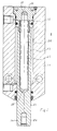
- the tool holder 8 consists of a cylinder housing 21 in the one Piston 22 is guided with piston rod 23.
- the piston rod 23 is for tool holder tapered in the tool mounting area 24. This is when tool holder the tools with tapered bore ensure a tight fit.
- the piston rod 23 is hollow in its interior.
- This cavity 25 can designed to be versatile, e.g. as triangular or polygonal or with oval cross section or also wedge-shaped.
- the foot part 26 of the cylinder housing 21 is designed as a closing part and at the same time with a press bore 27 into which a guide rod 28 is pressed.
- This Guide rod 28 is guided within the cavity 25 so that the piston rod 23 slides on the guide rod 28 in the cylinder housing 21.
- the Cavity design of the cavity 25 must also the design of the guide rod 28th be. This determines the position of the piston rod 23, i.e. the Piston rod 23 slides non-rotatably on the guide rod 28.
- the piston rod 23 is conical Tool attachment area 24 determined. If it often happens that the Tools need to be changed, a quick release device is required remains on the piston rod 23 and in turn receives the individual tools.
- a quick release coupling 29 can be provided for this.
- the Quick release coupling 29 has a conical bore 30 with which it is on the piston rod 23 is applied.
- a ball ring 31, on the circumference of which is used to hold the tool Inside a row of balls 32 are arranged in a corresponding receptacle.
- This Ball ring is slidably inserted in the housing 33 of the quick release coupling, so that it is in a certain area is axially displaceable in the direction of the arrow. By this shift the balls are moved inside the ring.
- the balls 32 are in the ball ring 31 in Bores 34 are guided and supported on the housing 33.
- the housing 33 has inside a circumferential groove 35 in which the balls 32 can be received.
- the ball ring 31 In its working position, the ball ring 31 is seated in the position shown in FIG. 6.
- the Balls lie on the inner surface of the housing 33 and press through the bores 34 through without being able to exit this hole.
- An introduced tool 36 that is provided with a circumferential groove in the area of the ball ring, is thus in its Position held immovably because the balls engage in its groove. Will the ball ring 31 however moved (see arrow direction Fig. 6), the balls are in the groove 35 of the Housing 33 pressed and thus come out of the area of effect of the introduced Tool that can now be removed.
- the tool holder on the piston rod 23 should be such that it is secure against rotation.
- the piston rod 23 is secured against rotation introduced in the cylinder housing 21.
- This backup also applies to the applied one Quick release coupling 29, but not so easily for those included therein Tools.
- Around these tools 36 in the quick release coupling 29 also secure against rotation is to be made in the quick release coupling 29 inside, i.e. in the wall at the inserted tool rests, a longitudinal groove 37 axially milled.
- Each tool also receives a pin that protrudes from the shank and has the thickness that corresponds to the longitudinal groove.
- the tool is inserted into the Quick-release coupling 29 guided with its pin in the longitudinal groove 37. That’s it Tool inserted against rotation.
Landscapes
- Engineering & Computer Science (AREA)
- Mechanical Engineering (AREA)
- Jigs For Machine Tools (AREA)
- Workshop Equipment, Work Benches, Supports, Or Storage Means (AREA)
- Seal Device For Vehicle (AREA)
- Electrical Discharge Machining, Electrochemical Machining, And Combined Machining (AREA)
- Auxiliary Devices For And Details Of Packaging Control (AREA)
Claims (9)
- Dispositif de montage à usiner des pièces d'oeuvre sur des bancs ou des palettes, comprenant un élément de support porté par une traverse de montage et un dispositif de raccordement d'outil pour outils différents, caractérisé en ce que ladite traverse de montage (2) a une configuration en U et que des alésages (3) sont formés, aux courtes distances, dans les deux côtés opposés dudit élément en U afin de fixer des éléments d'usinage et de (4 et 5) qui sont introduites dans ladite traverse de montage et sont aptes à être variés en leurs écarts mutuels et positionnés dans lesdits alésage, en ce que ladite traverse de montage est fixée sur une colonne (13) qui est rigidement montée sur une plaque de montage (12) pour un mouvement via un système de guidage linéaire (11), et en ce qu'un dispositif de raccordement d'outil (8), qui est fixé de façon à empêcher tout mouvement rotatoire, est affecté audit élément d'usinage (4).
- Dispositif de montage selon la revendication 1, caractérisé en ce que lesdits éléments d'usinage et de support (4 et 5) sont aptes à être déplacés et renversés en leur orientation.
- Dispositif de montage selon la revendication 1, caractérisé en ce qu'un dispositif de raccordement d'outil est affecté audit élément d'usinage (4), qui comprend une tige de piston (23) renfermant un creux (25), et en ce qu'une barre conductrice (28) est disposée à l'intérieur dudit creux (25), qui est fixée dans la base (26) du carter cylindrique.
- Dispositif de montage selon la revendication 3, caractérisé en ce que ledit creux (25) et ladite barre conductrice (28) ont un profil tel que tout mouvement rotatoire soit sûrement empêché.
- Dispositif de montage selon la revendication 4, caractérisé en ce que ladite tige de piston (23) est légèrement en cône à son extrémité qui sert à raccorder l'outil.
- Dispositif de montage selon les revendications 1 à 5, caractérisé en ce qu'un coupleur à serrage rapide (29) est affecté audit dispositif de raccordement d'outil (8), qui comprend un anneau de roulement à billes (31) avec des billes (32) qui sont aptes à être déplacées, par déplacement de l'anneau, en dehors de leur plan de service, et en ce qu'une rainure longitudinale (37) est ménagée dans la zone d'introduction d'outil, à une cheville étant disposée à glissement dans ladite rainure et étant affecté à la tige d'outil et arrêtant l'outil de façon à empêcher toute rotation.
- Dispositif de montage selon la revendication 1, caractérisé en ce que ledit système de guidage linéaire consiste en une coulisse (16) rigidement reliée à ladite traverse de montage (2) et glissant entre des galets (15) disposés en paires, et en ce que lesdits galets (15) sont rigidement montés sur ladite colonne (13).
- Dispositif de montage selon la revendication 7, caractérisé en ce qu'un cylindre (17) est monté sur ladite colonne (13) à un point de raccordement, et présente une tige de piston (19) fixée via un entraineur (20) sur ladite traverse de montage (2) de façon qu'après la sollicitation en compression via ledit système de guidage linéaire il est possible de lever ladite traverse de montage (2), et ensemble avec lui lesdits éléments (4 et 5).
- Dispositif de montage selon la revendication 8, caractérisé en ce que l'effort à introduire dans ledit cylindre (17) est un peu plus grand que l'effort requis à dépasser le poids de ladite (2) traverse de montage avec ses éléments (4 et 5) et des autres pièces.
Applications Claiming Priority (2)
| Application Number | Priority Date | Filing Date | Title |
|---|---|---|---|
| DE4432290A DE4432290A1 (de) | 1994-09-11 | 1994-09-11 | Montagegerät |
| DE4432290 | 1994-09-13 |
Publications (2)
| Publication Number | Publication Date |
|---|---|
| EP0701879A1 EP0701879A1 (fr) | 1996-03-20 |
| EP0701879B1 true EP0701879B1 (fr) | 1998-12-23 |
Family
ID=6527915
Family Applications (1)
| Application Number | Title | Priority Date | Filing Date |
|---|---|---|---|
| EP95114086A Expired - Lifetime EP0701879B1 (fr) | 1994-09-11 | 1995-09-08 | Dispositif de montage |
Country Status (3)
| Country | Link |
|---|---|
| EP (1) | EP0701879B1 (fr) |
| AT (1) | ATE174833T1 (fr) |
| DE (2) | DE4432290A1 (fr) |
Families Citing this family (3)
| Publication number | Priority date | Publication date | Assignee | Title |
|---|---|---|---|---|
| CN103934661A (zh) * | 2014-04-29 | 2014-07-23 | 江苏天鹏机电制造有限公司 | 一种单段锤式破碎机抽轴装置 |
| CN107618003A (zh) * | 2017-10-30 | 2018-01-23 | 二重集团(镇江)重型装备厂有限责任公司 | 一种用于大型容器内件的装配机构 |
| CN112743489A (zh) * | 2019-10-30 | 2021-05-04 | 沪东重机有限公司 | 气动阀件阀芯用拆装装置 |
Family Cites Families (16)
| Publication number | Priority date | Publication date | Assignee | Title |
|---|---|---|---|---|
| US2106525A (en) * | 1936-07-23 | 1938-01-25 | J G Brill Co | Universal tool holder |
| US3538794A (en) * | 1968-04-05 | 1970-11-10 | Leonard W Sandman | Portable tool attachment |
| SU591305A1 (ru) * | 1976-03-19 | 1978-02-05 | Medvid Markiyan Vasilevich | Ориентирующее устройство |
| DE3043149C2 (de) * | 1980-11-15 | 1987-05-14 | Daimler-Benz Ag, 7000 Stuttgart | Handnietpresse |
| DE3120247A1 (de) * | 1981-05-21 | 1983-02-24 | Richard 8752 Laufach Sauer | "bohrvorrichtung fuer eine motorbetriebene handbohrmaschine" |
| FR2509649A1 (fr) * | 1981-07-17 | 1983-01-21 | Aioi Seiki Kk | Palette porte-ouvrages pour machine-outil |
| DE3374185D1 (en) * | 1982-12-10 | 1987-12-03 | Wood Jeffrey | Portable workbench |
| ATE44903T1 (de) * | 1983-03-09 | 1989-08-15 | Hans Forrer | Mehrzweck-spanngeraet zur bearbeitung von werkstuecken, insbesondere von solchen aus holz. |
| DE3540221C1 (de) * | 1985-11-13 | 1986-10-16 | Horst Witte Entwicklungs- und Vertriebs KG, 2122 Bleckede | System zum Aufbau von Vorrichtungen zum Aufspannen von Werkstuecken |
| SU1340973A1 (ru) * | 1986-01-02 | 1987-09-30 | Центральное Межотраслевое Конструкторско-Технологическое Бюро Робототехники С Опытным Производством Института Физики Ан Латвсср-Центр Робототехники | Загрузочное устройство |
| IT1206886B (it) * | 1987-02-03 | 1989-05-11 | Dea Spa | Attrezzatura riconfigurabile per il sostegno ed il posizionamento dicorpi particolarmente di pezzi atti ad essere misurati da una macchina di misura |
| DE8705925U1 (de) * | 1987-04-21 | 1987-08-20 | H. Berthold AG, 12247 Berlin | Mobiler Montage- und Materialträger für eine Fertigungsstraße |
| DE3801813A1 (de) * | 1988-01-22 | 1989-08-03 | Zeiss Carl Fa | Spannsystem zur aufspannung von werkstuecken fuer messaufgaben |
| DE3819339A1 (de) * | 1988-06-07 | 1989-12-14 | Otto Michael Dr Ing Militzer | Grundplatten zum aufbau von spannvorrichtungen |
| DE4028076A1 (de) * | 1990-09-05 | 1992-03-12 | Hoefler Messgeraetebau Gmbh Dr | Messeinrichtung fuer rotationssymmetrische werkstuecke |
| DE4132655B4 (de) * | 1991-10-01 | 2004-08-05 | Pagel, Wolfgang | Vorrichtung zum Positionieren eines Objektes, beispielsweise eines Werkstückes |
-
1994
- 1994-09-11 DE DE4432290A patent/DE4432290A1/de not_active Withdrawn
-
1995
- 1995-09-08 EP EP95114086A patent/EP0701879B1/fr not_active Expired - Lifetime
- 1995-09-08 DE DE59504618T patent/DE59504618D1/de not_active Expired - Lifetime
- 1995-09-08 AT AT95114086T patent/ATE174833T1/de not_active IP Right Cessation
Also Published As
| Publication number | Publication date |
|---|---|
| DE59504618D1 (de) | 1999-02-04 |
| EP0701879A1 (fr) | 1996-03-20 |
| DE4432290A1 (de) | 1996-03-14 |
| ATE174833T1 (de) | 1999-01-15 |
Similar Documents
| Publication | Publication Date | Title |
|---|---|---|
| EP0480299B1 (fr) | Moyen de serrage multiple pour le serrage d'au moins deux pièces | |
| EP0298221B1 (fr) | Dispositif pour fraiser des rainures | |
| EP1140400B1 (fr) | Outil a enlevement de copeaux pour usinage a vitesse elevee | |
| DE2857655C2 (de) | Vorrichtung zum Aufspannen von Wirkstücken auf einem Werkzeugmaschinentisch | |
| DE10154139A1 (de) | Spannelement mit Schiebespannpratze | |
| EP0761382B1 (fr) | Dispositif à positionner des pièces dans des dispositifs de serrage | |
| EP0701879B1 (fr) | Dispositif de montage | |
| DE2041435A1 (de) | Kombinationswerkzeughalter fuer Drehbaenke | |
| EP0824998B1 (fr) | Outil pour la manutention d'une machine-outil | |
| DE2852254C2 (de) | Vorrichtung zur verschwenk-, verschieb- und feststellbaren Lagerung eines Schraubstockes auf einer Arbeitsunterlage, wie Werkbank oder dgl., insbesondere für leichte Bohrarbeiten (hinsichtlich der Bohrkräfte) | |
| EP0215182B1 (fr) | Fraiseuse-aléseuse | |
| DE3216929C2 (de) | Fräs=Vorrichtung zum Entgraten von Werkstücken | |
| DE559290C (de) | Werkzeugtraeger fuer Parallel-Drehbaenke | |
| DE3842963A1 (de) | Werktisch fuer handwerkzeugmaschinen | |
| DE19529287A1 (de) | Bohrlochtiefenanschlag | |
| DE3214284C2 (de) | Maschinen-Schraubstock | |
| EP2045041B1 (fr) | Dispositif de manipulation pour un support d'outil doté d'un dispositif de guidage | |
| DE202005019797U1 (de) | Verschiebemodul und Haltevorrichtung für ein Verschiebemodul | |
| DE1267937B (de) | Revolver-Drehautomat | |
| DE3508496A1 (de) | Handgefuehrte vorrichtung zum profilfraesen an werkstuecken aus holz, insbesondere an handlaeufen fuer treppengelaender | |
| DE1602839C3 (de) | Drehmaschine mit einer Einrichtung zur Zentrierverstellung des Werkzeughalters | |
| DE1427011C (de) | Werkstuckaufspanntisch | |
| DE882506C (de) | Auswechselbarer Werkzeughalter | |
| CH395698A (de) | Einspannvorrichtung für zu bearbeitende Werkstücke | |
| DE972859C (de) | Werkzeug, insbesondere zum Einstechen von Ringnuten |
Legal Events
| Date | Code | Title | Description |
|---|---|---|---|
| PUAI | Public reference made under article 153(3) epc to a published international application that has entered the european phase |
Free format text: ORIGINAL CODE: 0009012 |
|
| AK | Designated contracting states |
Kind code of ref document: A1 Designated state(s): AT CH DE ES FR GB IT LI |
|
| 17P | Request for examination filed |
Effective date: 19960823 |
|
| 17Q | First examination report despatched |
Effective date: 19970416 |
|
| GRAG | Despatch of communication of intention to grant |
Free format text: ORIGINAL CODE: EPIDOS AGRA |
|
| GRAG | Despatch of communication of intention to grant |
Free format text: ORIGINAL CODE: EPIDOS AGRA |
|
| GRAH | Despatch of communication of intention to grant a patent |
Free format text: ORIGINAL CODE: EPIDOS IGRA |
|
| GRAH | Despatch of communication of intention to grant a patent |
Free format text: ORIGINAL CODE: EPIDOS IGRA |
|
| GRAA | (expected) grant |
Free format text: ORIGINAL CODE: 0009210 |
|
| AK | Designated contracting states |
Kind code of ref document: B1 Designated state(s): AT CH DE ES FR GB IT LI |
|
| PG25 | Lapsed in a contracting state [announced via postgrant information from national office to epo] |
Ref country code: ES Free format text: THE PATENT HAS BEEN ANNULLED BY A DECISION OF A NATIONAL AUTHORITY Effective date: 19981223 |
|
| REF | Corresponds to: |
Ref document number: 174833 Country of ref document: AT Date of ref document: 19990115 Kind code of ref document: T |
|
| REG | Reference to a national code |
Ref country code: CH Ref legal event code: EP |
|
| REF | Corresponds to: |
Ref document number: 59504618 Country of ref document: DE Date of ref document: 19990204 |
|
| GBT | Gb: translation of ep patent filed (gb section 77(6)(a)/1977) |
Effective date: 19990128 |
|
| ET | Fr: translation filed | ||
| ITF | It: translation for a ep patent filed | ||
| PG25 | Lapsed in a contracting state [announced via postgrant information from national office to epo] |
Ref country code: AT Free format text: LAPSE BECAUSE OF NON-PAYMENT OF DUE FEES Effective date: 19990908 |
|
| PG25 | Lapsed in a contracting state [announced via postgrant information from national office to epo] |
Ref country code: LI Free format text: LAPSE BECAUSE OF NON-PAYMENT OF DUE FEES Effective date: 19990930 Ref country code: CH Free format text: LAPSE BECAUSE OF NON-PAYMENT OF DUE FEES Effective date: 19990930 |
|
| PLBE | No opposition filed within time limit |
Free format text: ORIGINAL CODE: 0009261 |
|
| STAA | Information on the status of an ep patent application or granted ep patent |
Free format text: STATUS: NO OPPOSITION FILED WITHIN TIME LIMIT |
|
| 26N | No opposition filed | ||
| REG | Reference to a national code |
Ref country code: CH Ref legal event code: PL |
|
| PGFP | Annual fee paid to national office [announced via postgrant information from national office to epo] |
Ref country code: GB Payment date: 20010723 Year of fee payment: 7 |
|
| PGFP | Annual fee paid to national office [announced via postgrant information from national office to epo] |
Ref country code: FR Payment date: 20010920 Year of fee payment: 7 |
|
| REG | Reference to a national code |
Ref country code: GB Ref legal event code: IF02 |
|
| PG25 | Lapsed in a contracting state [announced via postgrant information from national office to epo] |
Ref country code: GB Free format text: LAPSE BECAUSE OF NON-PAYMENT OF DUE FEES Effective date: 20020908 |
|
| GBPC | Gb: european patent ceased through non-payment of renewal fee |
Effective date: 20020908 |
|
| PG25 | Lapsed in a contracting state [announced via postgrant information from national office to epo] |
Ref country code: FR Free format text: LAPSE BECAUSE OF NON-PAYMENT OF DUE FEES Effective date: 20030603 |
|
| REG | Reference to a national code |
Ref country code: FR Ref legal event code: ST |
|
| PG25 | Lapsed in a contracting state [announced via postgrant information from national office to epo] |
Ref country code: IT Free format text: LAPSE BECAUSE OF NON-PAYMENT OF DUE FEES;WARNING: LAPSES OF ITALIAN PATENTS WITH EFFECTIVE DATE BEFORE 2007 MAY HAVE OCCURRED AT ANY TIME BEFORE 2007. THE CORRECT EFFECTIVE DATE MAY BE DIFFERENT FROM THE ONE RECORDED. Effective date: 20050908 |
|
| REG | Reference to a national code |
Ref country code: DE Ref legal event code: R082 Ref document number: 59504618 Country of ref document: DE Representative=s name: ZACCO DR. PETERS UND PARTNER, DE |
|
| PGFP | Annual fee paid to national office [announced via postgrant information from national office to epo] |
Ref country code: DE Payment date: 20140930 Year of fee payment: 20 |
|
| REG | Reference to a national code |
Ref country code: DE Ref legal event code: R071 Ref document number: 59504618 Country of ref document: DE |