EP0701912A2 - Bandage pneumatique - Google Patents
Bandage pneumatique Download PDFInfo
- Publication number
- EP0701912A2 EP0701912A2 EP95306288A EP95306288A EP0701912A2 EP 0701912 A2 EP0701912 A2 EP 0701912A2 EP 95306288 A EP95306288 A EP 95306288A EP 95306288 A EP95306288 A EP 95306288A EP 0701912 A2 EP0701912 A2 EP 0701912A2
- Authority
- EP
- European Patent Office
- Prior art keywords
- belt layer
- layer
- rubber
- circumferential
- coating rubber
- Prior art date
- Legal status (The legal status is an assumption and is not a legal conclusion. Google has not performed a legal analysis and makes no representation as to the accuracy of the status listed.)
- Granted
Links
- 239000011248 coating agent Substances 0.000 claims abstract description 53
- 238000000576 coating method Methods 0.000 claims abstract description 53
- 230000003014 reinforcing effect Effects 0.000 claims abstract description 18
- 239000011324 bead Substances 0.000 claims description 3
- 238000005728 strengthening Methods 0.000 abstract description 5
- 230000020169 heat generation Effects 0.000 description 14
- 238000000926 separation method Methods 0.000 description 10
- 230000001965 increasing effect Effects 0.000 description 7
- 238000010276 construction Methods 0.000 description 5
- 230000000452 restraining effect Effects 0.000 description 5
- 238000006073 displacement reaction Methods 0.000 description 4
- 230000000052 comparative effect Effects 0.000 description 2
- 230000007423 decrease Effects 0.000 description 2
- 238000004519 manufacturing process Methods 0.000 description 2
- 238000009864 tensile test Methods 0.000 description 2
- 230000009466 transformation Effects 0.000 description 2
- 238000010073 coating (rubber) Methods 0.000 description 1
- 239000012141 concentrate Substances 0.000 description 1
- 230000003247 decreasing effect Effects 0.000 description 1
- 230000006866 deterioration Effects 0.000 description 1
- 230000002708 enhancing effect Effects 0.000 description 1
- 230000000116 mitigating effect Effects 0.000 description 1
- 230000008719 thickening Effects 0.000 description 1
- 238000004073 vulcanization Methods 0.000 description 1
Images

Classifications
-
- B—PERFORMING OPERATIONS; TRANSPORTING
- B60—VEHICLES IN GENERAL
- B60C—VEHICLE TYRES; TYRE INFLATION; TYRE CHANGING; CONNECTING VALVES TO INFLATABLE ELASTIC BODIES IN GENERAL; DEVICES OR ARRANGEMENTS RELATED TO TYRES
- B60C9/00—Reinforcements or ply arrangement of pneumatic tyres
- B60C9/18—Structure or arrangement of belts or breakers, crown-reinforcing or cushioning layers
- B60C9/20—Structure or arrangement of belts or breakers, crown-reinforcing or cushioning layers built-up from rubberised plies each having all cords arranged substantially parallel
- B60C9/22—Structure or arrangement of belts or breakers, crown-reinforcing or cushioning layers built-up from rubberised plies each having all cords arranged substantially parallel the plies being arranged with all cords disposed along the circumference of the tyre
- B60C9/2204—Structure or arrangement of belts or breakers, crown-reinforcing or cushioning layers built-up from rubberised plies each having all cords arranged substantially parallel the plies being arranged with all cords disposed along the circumference of the tyre obtained by circumferentially narrow strip winding
-
- B—PERFORMING OPERATIONS; TRANSPORTING
- B60—VEHICLES IN GENERAL
- B60C—VEHICLE TYRES; TYRE INFLATION; TYRE CHANGING; CONNECTING VALVES TO INFLATABLE ELASTIC BODIES IN GENERAL; DEVICES OR ARRANGEMENTS RELATED TO TYRES
- B60C9/00—Reinforcements or ply arrangement of pneumatic tyres
- B60C9/0064—Reinforcements comprising monofilaments
-
- B—PERFORMING OPERATIONS; TRANSPORTING
- B60—VEHICLES IN GENERAL
- B60C—VEHICLE TYRES; TYRE INFLATION; TYRE CHANGING; CONNECTING VALVES TO INFLATABLE ELASTIC BODIES IN GENERAL; DEVICES OR ARRANGEMENTS RELATED TO TYRES
- B60C9/00—Reinforcements or ply arrangement of pneumatic tyres
- B60C9/18—Structure or arrangement of belts or breakers, crown-reinforcing or cushioning layers
- B60C9/20—Structure or arrangement of belts or breakers, crown-reinforcing or cushioning layers built-up from rubberised plies each having all cords arranged substantially parallel
- B60C9/2003—Structure or arrangement of belts or breakers, crown-reinforcing or cushioning layers built-up from rubberised plies each having all cords arranged substantially parallel characterised by the materials of the belt cords
- B60C9/2009—Structure or arrangement of belts or breakers, crown-reinforcing or cushioning layers built-up from rubberised plies each having all cords arranged substantially parallel characterised by the materials of the belt cords comprising plies of different materials
-
- B—PERFORMING OPERATIONS; TRANSPORTING
- B60—VEHICLES IN GENERAL
- B60C—VEHICLE TYRES; TYRE INFLATION; TYRE CHANGING; CONNECTING VALVES TO INFLATABLE ELASTIC BODIES IN GENERAL; DEVICES OR ARRANGEMENTS RELATED TO TYRES
- B60C9/00—Reinforcements or ply arrangement of pneumatic tyres
- B60C9/18—Structure or arrangement of belts or breakers, crown-reinforcing or cushioning layers
- B60C9/20—Structure or arrangement of belts or breakers, crown-reinforcing or cushioning layers built-up from rubberised plies each having all cords arranged substantially parallel
- B60C2009/2061—Physical properties or dimensions of the belt coating rubber
- B60C2009/2064—Modulus; Hardness; Loss modulus or "tangens delta"
-
- B—PERFORMING OPERATIONS; TRANSPORTING
- B60—VEHICLES IN GENERAL
- B60C—VEHICLE TYRES; TYRE INFLATION; TYRE CHANGING; CONNECTING VALVES TO INFLATABLE ELASTIC BODIES IN GENERAL; DEVICES OR ARRANGEMENTS RELATED TO TYRES
- B60C9/00—Reinforcements or ply arrangement of pneumatic tyres
- B60C9/18—Structure or arrangement of belts or breakers, crown-reinforcing or cushioning layers
- B60C9/20—Structure or arrangement of belts or breakers, crown-reinforcing or cushioning layers built-up from rubberised plies each having all cords arranged substantially parallel
- B60C9/22—Structure or arrangement of belts or breakers, crown-reinforcing or cushioning layers built-up from rubberised plies each having all cords arranged substantially parallel the plies being arranged with all cords disposed along the circumference of the tyre
- B60C2009/2238—Physical properties or dimensions of the ply coating rubber
- B60C2009/2242—Modulus; Hardness; Loss modulus or "tangens delta"
-
- Y—GENERAL TAGGING OF NEW TECHNOLOGICAL DEVELOPMENTS; GENERAL TAGGING OF CROSS-SECTIONAL TECHNOLOGIES SPANNING OVER SEVERAL SECTIONS OF THE IPC; TECHNICAL SUBJECTS COVERED BY FORMER USPC CROSS-REFERENCE ART COLLECTIONS [XRACs] AND DIGESTS
- Y10—TECHNICAL SUBJECTS COVERED BY FORMER USPC
- Y10T—TECHNICAL SUBJECTS COVERED BY FORMER US CLASSIFICATION
- Y10T152/00—Resilient tires and wheels
- Y10T152/10—Tires, resilient
- Y10T152/10495—Pneumatic tire or inner tube
- Y10T152/10765—Characterized by belt or breaker structure
- Y10T152/10783—Reinforcing plies made up from wound narrow ribbons
-
- Y—GENERAL TAGGING OF NEW TECHNOLOGICAL DEVELOPMENTS; GENERAL TAGGING OF CROSS-SECTIONAL TECHNOLOGIES SPANNING OVER SEVERAL SECTIONS OF THE IPC; TECHNICAL SUBJECTS COVERED BY FORMER USPC CROSS-REFERENCE ART COLLECTIONS [XRACs] AND DIGESTS
- Y10—TECHNICAL SUBJECTS COVERED BY FORMER USPC
- Y10T—TECHNICAL SUBJECTS COVERED BY FORMER US CLASSIFICATION
- Y10T152/00—Resilient tires and wheels
- Y10T152/10—Tires, resilient
- Y10T152/10495—Pneumatic tire or inner tube
- Y10T152/10765—Characterized by belt or breaker structure
- Y10T152/1081—Breaker or belt characterized by the chemical composition or physical properties of elastomer or the like
Definitions
- This invention relates to a pneumatic tire, and in particular to a pneumatic tire wherein the crown portion of the carcass thereof is reinforced by a circumferential belt layer comprising reinforcing elements arranged substantially in parallel with the equatorial plane of the tire in straight, wavy or zigzag form.
- Japanese Patent Application Laid-Open No. 2-81706 discloses a tire comprising a circumferential belt layer for strengthening the circumferential rigidity which comprises wavy reinforcing elements and attaining vulcanisation almost without preventing expansion of the diameter of the belt in tire manufacture.
- the addition of the circumferential belt layer causes an increase in the heat generation of the belt, because of not only increasing the thickness of the belt but also increasing the strain generated between the circumferential belt layer and inclined belt layer during rotation of the tire. Also the heat generation of the belt causes deterioration of the coating rubber of the belt and finally causes so-called "heat separation" between the cords and the coating rubber.
- the tread and the belt in the ground-contacting area of the tread are compressed radially inwards, and therefore the rubber coating reinforcing elements of the belt moves toward the belt edge portions.
- the quantity of displacement of the coating rubber becomes a maximum at the belt edge portions, especially at the edge portions of the circumferential belt layer, because the displacement of the coating rubber in the width direction is restricted. Therefore strain concentrates at the edge portions of the circumferential belt layer to cause separation.
- an object of the present invention to provide a tire which overcomes the disadvantage caused by addition of a circumferential belt layer, especially belt separation, while strengthening the circumferential rigidity by the addition of the circumferential belt layer.
- the present invention provides a pneumatic tire comprising a belt and a tread disposed radially outside the crown portion of a carcass toroidally extending between a pair of beads, said belt being a laminate of a circumferential belt layer and an inclined belt layer, said circumferential belt layer comprising a plurality of reinforcing elements arranged substantially in parallel with the equatorial plane of the tire and coated with rubber, and said inclined belt layer comprising a plurality of reinforcing elements inclined with respect to the equatorial plane of the tire and coated with rubber, characterised in that, at least as regards the coating rubber of said circumferential belt layer and the coating rubber of said inclined belt layer adjoining each other, the coating rubber of the circumferential belt layer has a lower modulus of elasticity than that of the coating rubber of the inclined belt layer.
- the thickness of the coating rubber of the circumferential belt layer accounting for said rubber layer is larger than the thickness of the coating rubber of said inclined belt layer.
- a control rubber layer having a higher modulus of elasticity than that of said coating rubber of the circumferential belt layer is disposed outside of the widthwise edge of said circumferential belt layer.
- circumferential belt layer there can be applied not only the usual structure in which substantially straight cords or monofilaments as the reinforcing elements are arranged in the circumferential direction, but also a structure in which wavy cords or monofilaments are used and a structure in which a ribbon comprising several cords or monofilaments coated with rubber is spirally wound.
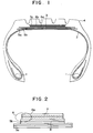
- Fig. 1 illustrates the section of a typical pneumatic tire in the tire width direction, according to the invention.
- This pneumatic tire has a belt 3 comprising at least one inclined belt layer 5a, 5b and at least one circumferential belt layer 6a, 6b, and a tread 4 disposed radially outside the crown portion of a carcass 2 toroidally extending between a pair of beads 1.
- the belt 3 comprises two circumferential belt layers 6a, 6b disposed radially outside two inclined belt layers 5a, 5b which are in turn disposed radially outside the carcass 2.
- the reference 5c indicates a belt-protection layer covering the outermost layer of the belt 3, which can be omitted.
- the coating rubber of the circumferential belt layer 6a has a lower modulus of elasticity than that of the coating rubber layer of the inclined belt layer 5b. That is, lowering the modulus of elasticity decreases heat generation at the belt 3.
- the coating rubber of the circumferential belt layer 6a has a lower modulus of elasticity than that of the coating rubber of the adjoining inclined belt layer 5b, in a similar manner the coating rubber of the circumferential belt layer 6b can have a lower modulus of elasticity than that of the coating rubber of the inclined belt layer 5a.
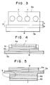
- the thickness (tc) of the coating rubber of the circumferential belt layer 6a is larger than the thickness (ts) of the coating rubber of the inclined belt layer 5b. That is, the ratio of the coating rubber of the circumferential belt layer 6a accounting for the rubber layer 9 is larger than that of the coating rubber of the inclined belt layer 5b, as a result of which the strain concentrating especially at the vicinity of the circumferential belt layer 6a is mitigated.
- Fig. 4 illustrates, disposing a control rubber layer 10 having a higher modulus of elasticity than that of the coating rubber of the circumferential belt layer 6a outside both the widthwise edges of the circumferential belt layer 6a restricts the displacement of the coating rubber of the circumferential belt layer, which is effective in restraining the strain at the circumferential belt layer 6a.
- lowering the modulus of elasticity of the coating rubber of the circumferential belt layer 6a, and also increasing the thickness tc of the coating rubber of the circumferential belt layer 6a accounting for the rubber layer 9 relative to the thickness ts of the coating rubber of the adjoining inclined belt layer 5b, and/or disposing the control rubber layer 10 outside both edges of the circumferential belt layer 6a decreases heat generation and restrains separation at the belt ends.
- the arrangement of the circumferential belt layer and inclined belt layer is not limited to the embodiments shown in Figs. 2, 3 and 4.
- two circumferential belt layers 6a, 6b can be disposed radially below two inclined belt layers 5a, 5b on the carcass.
- the modulus of elasticity of the coating rubber of the circumferential belt layer 6a is lower than that of the adjoining inclined belt layer 5b.
- a tire having a belt which comprises an inclined belt layer in addition to a circumferential belt layer has the problem of belt separation caused by heat generation and the strain concentrating at both edges of the circumferential belt layer(s).
- strain energy (modulus of elasticity)x(strain)
- the modulus of elasticity of the coating rubber of the circumferential belt layer is 20-45 kgf/mm as the value of stress in a 100% tensile test at room temperature.
- the modulus of elasticity of the coating rubber of the inclined belt layer because said modulus is 55-65 kgf/mm as a value of stress in a 100% tensile test at room temperature that can maintain the rigidity of the belt, it is preferable when restraining heat generation to set the modulus in the vicinity of the lower limit.
- the ability to mitigate the strain generated is enhanced by increasing the ratio of the coating rubber of the circumferential belt layer of which the modulus of elasticity is lowered accounting for the rubber layer, and such a large strain concentration as to cause the separation is restrained. It is preferable that the ratio of the coating rubber of the circumferential belt layer accounting for the rubber layer 9 is in the range of more than 0.5 - 0.7. Because thickening the whole rubber layer is disadvantageous for restraining heat generation, the strain mitigation ability of the rubber layer is improved by enhancing the ratio of the coating rubber of the circumferential belt layer, and furthermore the rigidity of the inclined belt layer and the minimum required thickness of the inclined belt layer in tire manufacture are secured, respectively.
- control rubber layer 10 of which the modulus of elasticity is larger than that of the coating rubber of the circumferential belt layer 6a is disposed outside both edges of the circumferential belt layer respectively, by which separation may be avoided by restricting the displacement of the rubber layer during rotation under load and restraining the strain generation.
- the control rubber layers 10, as Figs. 4 and 7 illustrate, are disposed outside both edges of the circumferential belt layer and extend in the circumferential direction with a rectangular section, respectively. It is preferable that the modulus of elasticity of the control rubber is 1.3 - 3.0 times as much as that of the coating rubber of the circumferential belt layer. It is also preferable, to avoid heat generation which accompanies increasing the amount of the rubber, that the width and thickness of the section shape of the control rubber layer are 10 - 20 mm and 1.0 - 2.0 mm, respectively.
- pneumatic radial tires for trucks and buses having a tire size of 11/70R22.5 and a belt construction including a circumferential belt layer as illustrated in Figs. 1 and 2, as described in more detail in Table 1, respectively.
- the circumferential belt layer comprised wavy cords (0.8mm ⁇ , wave length: 36.6mm, amplitude: 1.3mm) of 3+9x0.19mm with end count: 28 cords/50mm.
- the inclined belt layer comprised cords (1. 4mm ⁇ ) of 3+9+15x0.23mm at an angle of 18° with respect to the equatorial plane of the tire with end count: 23 cords/50mm.
- the modulus of elasticity and the thickness of coating rubber of each belt layer are represented by a ratio on basis of a Comparative tire in which the modulus of elasticity and the thickness were 57 kgf/mm and 0.3 mm in the circumferential belt layer, and 57 kgf/mm and 0.3 mm in the inclined belt layer, respectively.
- the tire temperature was measured by stopping the drum ten hours after the tire had started to run on the drum and by inserting a thermocouple-type beam-thermometer into the vicinity of the edge portion of the circumferential belt layer.
Landscapes
- Engineering & Computer Science (AREA)
- Mechanical Engineering (AREA)
- Tires In General (AREA)
Applications Claiming Priority (3)
| Application Number | Priority Date | Filing Date | Title |
|---|---|---|---|
| JP223307/94 | 1994-09-19 | ||
| JP22330794A JP3556712B2 (ja) | 1994-09-19 | 1994-09-19 | 空気入りタイヤ |
| JP22330794 | 1994-09-19 |
Publications (3)
| Publication Number | Publication Date |
|---|---|
| EP0701912A2 true EP0701912A2 (fr) | 1996-03-20 |
| EP0701912A3 EP0701912A3 (fr) | 1996-08-21 |
| EP0701912B1 EP0701912B1 (fr) | 2000-05-31 |
Family
ID=16796103
Family Applications (1)
| Application Number | Title | Priority Date | Filing Date |
|---|---|---|---|
| EP95306288A Expired - Lifetime EP0701912B1 (fr) | 1994-09-19 | 1995-09-08 | Bandage pneumatique |
Country Status (5)
| Country | Link |
|---|---|
| US (3) | US5804002A (fr) |
| EP (1) | EP0701912B1 (fr) |
| JP (1) | JP3556712B2 (fr) |
| DE (1) | DE69517271T2 (fr) |
| ES (1) | ES2148446T3 (fr) |
Cited By (1)
| Publication number | Priority date | Publication date | Assignee | Title |
|---|---|---|---|---|
| EP1072444A4 (fr) * | 1998-10-20 | 2002-03-20 | Bridgestone Corp | Pneu radial resistant |
Families Citing this family (16)
| Publication number | Priority date | Publication date | Assignee | Title |
|---|---|---|---|---|
| JP3556712B2 (ja) * | 1994-09-19 | 2004-08-25 | 株式会社ブリヂストン | 空気入りタイヤ |
| JP4493107B2 (ja) * | 1997-03-17 | 2010-06-30 | 株式会社ブリヂストン | 重荷重用空気入りラジアルタイヤ |
| FR2765151A1 (fr) * | 1997-06-26 | 1998-12-31 | Michelin & Cie | Armature de sommet pour pneumatique radial |
| JP4112079B2 (ja) * | 1997-07-09 | 2008-07-02 | 株式会社ブリヂストン | 空気入りラジアルタイヤ |
| US6708747B1 (en) * | 1998-08-19 | 2004-03-23 | Bridgestone Corporation | Pneumatic radial tires |
| WO2000020233A1 (fr) * | 1998-10-02 | 2000-04-13 | Societe De Technologie Michelin | Armature de sommet pour pneumatique radial |
| JP2002067617A (ja) * | 2000-08-29 | 2002-03-08 | Sumitomo Rubber Ind Ltd | 空気入りタイヤ |
| JP4627886B2 (ja) * | 2001-01-10 | 2011-02-09 | 株式会社ブリヂストン | 複合強化ゴム材および空気入りタイヤ |
| US20040163748A1 (en) * | 2003-02-24 | 2004-08-26 | Kiyoshi Ueyoko | Tire having a composite belt structure |
| US7360571B2 (en) * | 2003-09-16 | 2008-04-22 | The Goodyear Tire & Rubber Company | Pneumatic tire with composite belt structure |
| US7216684B2 (en) * | 2003-12-29 | 2007-05-15 | The Goodyear Tire & Rubber Company | Pneumatic aviation tire |
| FR2897557B1 (fr) * | 2006-02-21 | 2008-04-18 | Michelin Soc Tech | Pneumatique pour vehicules |
| MX2008014942A (es) * | 2006-10-13 | 2008-12-09 | Michelin Rech Tech | Banda mejorada de cizallamiento. |
| JP6403673B2 (ja) * | 2013-08-29 | 2018-10-10 | 株式会社ブリヂストン | 空気入りタイヤとその製造方法 |
| US11511566B2 (en) | 2019-12-10 | 2022-11-29 | The Goodyear Tire & Rubber Company | Shear band |
| US12065003B2 (en) | 2021-03-29 | 2024-08-20 | The Goodyear Tire & Rubber Company | Shear band construction |
Family Cites Families (15)
| Publication number | Priority date | Publication date | Assignee | Title |
|---|---|---|---|---|
| FR1440084A (fr) * | 1965-04-14 | 1966-05-27 | Fr Du Pneu Englebert Soc | Ceinture de renforcement pour enveloppe pneumatique et nappe constitutive d'une telle ceinture |
| IT961632B (it) * | 1971-07-23 | 1973-12-10 | Toyo Tire & Rubber Co | Pneumatico a tele radiali |
| JPS5651923B2 (fr) * | 1972-12-29 | 1981-12-09 | ||
| DE2602424A1 (de) * | 1976-01-23 | 1977-07-28 | Phoenix Gummiwerke Ag | Guertelreifen |
| US5154217A (en) * | 1986-11-21 | 1992-10-13 | The Yokohama Rubber Co., Ltd. | Heavy-duty pneumatic tire preventing belt separation |
| JP2527801B2 (ja) * | 1988-03-09 | 1996-08-28 | 株式会社ブリヂストン | 帯状の積層補強体並びに空気入りタイヤ |
| JP3009671B2 (ja) * | 1988-09-19 | 2000-02-14 | 株式会社ブリヂストン | 重荷重用空気入りタイヤ |
| SU1648806A2 (ru) * | 1989-05-18 | 1991-05-15 | Научно-исследовательский институт шинной промышленности | Пневматическа радиальна шина |
| SU1648866A1 (ru) * | 1989-06-26 | 1991-05-15 | Астраханский Технологический Институт Рыбной Промышленности И Хозяйства | Перегрузочное устройство |
| JP2554215B2 (ja) * | 1990-08-08 | 1996-11-13 | 住友ゴム工業株式会社 | 自動二輪車用ラジアルタイヤ |
| JPH04126609A (ja) * | 1990-09-18 | 1992-04-27 | Bridgestone Corp | 航空機用更生バイアスタイヤ |
| JP3016622B2 (ja) * | 1991-04-27 | 2000-03-06 | 株式会社ブリヂストン | 空気入りラジアルタイヤ |
| JP3650134B2 (ja) * | 1992-07-28 | 2005-05-18 | 株式会社ブリヂストン | 空気入りタイヤ |
| JP3205396B2 (ja) * | 1992-07-28 | 2001-09-04 | 株式会社ブリヂストン | 空気入りタイヤ |
| JP3556712B2 (ja) * | 1994-09-19 | 2004-08-25 | 株式会社ブリヂストン | 空気入りタイヤ |
-
1994
- 1994-09-19 JP JP22330794A patent/JP3556712B2/ja not_active Expired - Fee Related
-
1995
- 1995-09-08 EP EP95306288A patent/EP0701912B1/fr not_active Expired - Lifetime
- 1995-09-08 US US08/525,025 patent/US5804002A/en not_active Expired - Lifetime
- 1995-09-08 DE DE69517271T patent/DE69517271T2/de not_active Expired - Lifetime
- 1995-09-08 ES ES95306288T patent/ES2148446T3/es not_active Expired - Lifetime
-
1998
- 1998-05-11 US US09/075,255 patent/US6098683A/en not_active Expired - Lifetime
-
2000
- 2000-02-29 US US09/515,847 patent/US6374890B1/en not_active Expired - Lifetime
Non-Patent Citations (1)
| Title |
|---|
| None |
Cited By (2)
| Publication number | Priority date | Publication date | Assignee | Title |
|---|---|---|---|---|
| EP1072444A4 (fr) * | 1998-10-20 | 2002-03-20 | Bridgestone Corp | Pneu radial resistant |
| US6615889B1 (en) | 1998-10-20 | 2003-09-09 | Bridgestone Corporation | Heavy duty radial tire |
Also Published As
| Publication number | Publication date |
|---|---|
| ES2148446T3 (es) | 2000-10-16 |
| JP3556712B2 (ja) | 2004-08-25 |
| US6098683A (en) | 2000-08-08 |
| DE69517271T2 (de) | 2001-01-04 |
| EP0701912A3 (fr) | 1996-08-21 |
| JPH0885307A (ja) | 1996-04-02 |
| US5804002A (en) | 1998-09-08 |
| US6374890B1 (en) | 2002-04-23 |
| DE69517271D1 (de) | 2000-07-06 |
| EP0701912B1 (fr) | 2000-05-31 |
Similar Documents
| Publication | Publication Date | Title |
|---|---|---|
| EP0701912B1 (fr) | Bandage pneumatique | |
| EP0484075B1 (fr) | Pneumatique radial pour moto | |
| EP1454766B1 (fr) | Pneu radial | |
| US4085787A (en) | Pneumatic tire for a vehicle having a radial carcass and improved beads | |
| EP0790143A1 (fr) | Bandage pneumatique radial | |
| US4100955A (en) | Pneumatic tire | |
| US5441093A (en) | Motorcycle radial tire with folded breaker ply and spirally wound band ply | |
| EP0204237B1 (fr) | Pneumatique radial pour automobiles | |
| EP0911188A1 (fr) | Bandage pneumatique apte à rouler à plat | |
| EP0850788B1 (fr) | Bandage pneumatique radial | |
| US4790366A (en) | Pneumatic radial tire for heavy duty vehicle | |
| EP1207055B1 (fr) | Bandage pneumatique | |
| EP0565339B1 (fr) | Bandage pneumatique pour moto | |
| EP0331453B1 (fr) | Pneumatique radial pour grandes vitesses et charges élevées | |
| US5225013A (en) | Pneumatic radial tire including wavy or zigzag belt cords | |
| EP0413574B1 (fr) | Pneumatique radial pour grandes vitesses | |
| US5036896A (en) | Pneumatic tire with oriented carcass plies, the plies having aramid filaments | |
| US5522443A (en) | High speed heavy duty tire and rim assembly whose tire includes a buffer layer in each bead portion | |
| EP0456438A2 (fr) | Pneumatique radial pour motos | |
| JP2000062411A (ja) | 空気入りラジアルタイヤ | |
| US6145560A (en) | Heavy duty pneumatic radial tires with specified belt cushion rubbers | |
| JPH03128702A (ja) | 重荷重用タイヤ | |
| EP0329592B1 (fr) | Bandage pneumatique | |
| US5151139A (en) | Heavy duty radial tire having durable buttress portion | |
| US4216813A (en) | Radial tire with a belt structure of different reinforcement cords |
Legal Events
| Date | Code | Title | Description |
|---|---|---|---|
| PUAI | Public reference made under article 153(3) epc to a published international application that has entered the european phase |
Free format text: ORIGINAL CODE: 0009012 |
|
| AK | Designated contracting states |
Kind code of ref document: A2 Designated state(s): DE ES FR GB IT |
|
| 17P | Request for examination filed |
Effective date: 19960425 |
|
| PUAL | Search report despatched |
Free format text: ORIGINAL CODE: 0009013 |
|
| AK | Designated contracting states |
Kind code of ref document: A3 Designated state(s): DE ES FR GB IT |
|
| 17Q | First examination report despatched |
Effective date: 19980121 |
|
| GRAG | Despatch of communication of intention to grant |
Free format text: ORIGINAL CODE: EPIDOS AGRA |
|
| GRAG | Despatch of communication of intention to grant |
Free format text: ORIGINAL CODE: EPIDOS AGRA |
|
| GRAH | Despatch of communication of intention to grant a patent |
Free format text: ORIGINAL CODE: EPIDOS IGRA |
|
| GRAH | Despatch of communication of intention to grant a patent |
Free format text: ORIGINAL CODE: EPIDOS IGRA |
|
| GRAA | (expected) grant |
Free format text: ORIGINAL CODE: 0009210 |
|
| AK | Designated contracting states |
Kind code of ref document: B1 Designated state(s): DE ES FR GB IT |
|
| REF | Corresponds to: |
Ref document number: 69517271 Country of ref document: DE Date of ref document: 20000706 |
|
| ITF | It: translation for a ep patent filed | ||
| ET | Fr: translation filed | ||
| REG | Reference to a national code |
Ref country code: ES Ref legal event code: FG2A Ref document number: 2148446 Country of ref document: ES Kind code of ref document: T3 |
|
| PLBE | No opposition filed within time limit |
Free format text: ORIGINAL CODE: 0009261 |
|
| STAA | Information on the status of an ep patent application or granted ep patent |
Free format text: STATUS: NO OPPOSITION FILED WITHIN TIME LIMIT |
|
| 26N | No opposition filed | ||
| REG | Reference to a national code |
Ref country code: GB Ref legal event code: IF02 |
|
| PGFP | Annual fee paid to national office [announced via postgrant information from national office to epo] |
Ref country code: ES Payment date: 20110921 Year of fee payment: 17 Ref country code: GB Payment date: 20110907 Year of fee payment: 17 |
|
| GBPC | Gb: european patent ceased through non-payment of renewal fee |
Effective date: 20120908 |
|
| PG25 | Lapsed in a contracting state [announced via postgrant information from national office to epo] |
Ref country code: GB Free format text: LAPSE BECAUSE OF NON-PAYMENT OF DUE FEES Effective date: 20120908 |
|
| REG | Reference to a national code |
Ref country code: ES Ref legal event code: FD2A Effective date: 20131018 |
|
| PG25 | Lapsed in a contracting state [announced via postgrant information from national office to epo] |
Ref country code: ES Free format text: LAPSE BECAUSE OF NON-PAYMENT OF DUE FEES Effective date: 20120909 |
|
| REG | Reference to a national code |
Ref country code: FR Ref legal event code: CA Effective date: 20140812 |
|
| REG | Reference to a national code |
Ref country code: DE Ref legal event code: R081 Ref document number: 69517271 Country of ref document: DE Owner name: BRIDGESTONE CORPORATION, JP Free format text: FORMER OWNER: BRIDGESTONE CORP., TOKIO/TOKYO, JP Effective date: 20140828 |
|
| PGFP | Annual fee paid to national office [announced via postgrant information from national office to epo] |
Ref country code: DE Payment date: 20140922 Year of fee payment: 20 |
|
| PGFP | Annual fee paid to national office [announced via postgrant information from national office to epo] |
Ref country code: FR Payment date: 20140919 Year of fee payment: 20 |
|
| PGFP | Annual fee paid to national office [announced via postgrant information from national office to epo] |
Ref country code: IT Payment date: 20140929 Year of fee payment: 20 |
|
| REG | Reference to a national code |
Ref country code: DE Ref legal event code: R071 Ref document number: 69517271 Country of ref document: DE |