EP0701963A1 - Chariot de manutention motorisé à bras téléscopique - Google Patents
Chariot de manutention motorisé à bras téléscopique Download PDFInfo
- Publication number
- EP0701963A1 EP0701963A1 EP95402069A EP95402069A EP0701963A1 EP 0701963 A1 EP0701963 A1 EP 0701963A1 EP 95402069 A EP95402069 A EP 95402069A EP 95402069 A EP95402069 A EP 95402069A EP 0701963 A1 EP0701963 A1 EP 0701963A1
- Authority
- EP
- European Patent Office
- Prior art keywords
- telescopic arm
- trolley
- trolley according
- pivot axis
- chassis
- Prior art date
- Legal status (The legal status is an assumption and is not a legal conclusion. Google has not performed a legal analysis and makes no representation as to the accuracy of the status listed.)
- Granted
Links
- 239000003381 stabilizer Substances 0.000 claims description 5
- 238000006073 displacement reaction Methods 0.000 description 12
- 238000010586 diagram Methods 0.000 description 4
- 238000000034 method Methods 0.000 description 4
- 239000004606 Fillers/Extenders Substances 0.000 description 3
- 239000012530 fluid Substances 0.000 description 3
- 238000009434 installation Methods 0.000 description 3
- 230000003068 static effect Effects 0.000 description 3
- 230000000694 effects Effects 0.000 description 2
- 230000005484 gravity Effects 0.000 description 2
- 238000004519 manufacturing process Methods 0.000 description 2
- 238000012986 modification Methods 0.000 description 2
- 230000004048 modification Effects 0.000 description 2
- 230000036961 partial effect Effects 0.000 description 2
- 230000002829 reductive effect Effects 0.000 description 2
- 238000010276 construction Methods 0.000 description 1
- 230000003247 decreasing effect Effects 0.000 description 1
- 238000013461 design Methods 0.000 description 1
- 238000009826 distribution Methods 0.000 description 1
- 238000005553 drilling Methods 0.000 description 1
- 238000012423 maintenance Methods 0.000 description 1
- 230000000284 resting effect Effects 0.000 description 1
- 238000005096 rolling process Methods 0.000 description 1
- 238000013519 translation Methods 0.000 description 1
Images


Classifications
-
- B—PERFORMING OPERATIONS; TRANSPORTING
- B66—HOISTING; LIFTING; HAULING
- B66F—HOISTING, LIFTING, HAULING OR PUSHING, NOT OTHERWISE PROVIDED FOR, e.g. DEVICES WHICH APPLY A LIFTING OR PUSHING FORCE DIRECTLY TO THE SURFACE OF A LOAD
- B66F9/00—Devices for lifting or lowering bulky or heavy goods for loading or unloading purposes
- B66F9/06—Devices for lifting or lowering bulky or heavy goods for loading or unloading purposes movable, with their loads, on wheels or the like, e.g. fork-lift trucks
- B66F9/075—Constructional features or details
- B66F9/07563—Fork-lift trucks adapted to be carried by transport vehicles
-
- B—PERFORMING OPERATIONS; TRANSPORTING
- B66—HOISTING; LIFTING; HAULING
- B66F—HOISTING, LIFTING, HAULING OR PUSHING, NOT OTHERWISE PROVIDED FOR, e.g. DEVICES WHICH APPLY A LIFTING OR PUSHING FORCE DIRECTLY TO THE SURFACE OF A LOAD
- B66F9/00—Devices for lifting or lowering bulky or heavy goods for loading or unloading purposes
- B66F9/06—Devices for lifting or lowering bulky or heavy goods for loading or unloading purposes movable, with their loads, on wheels or the like, e.g. fork-lift trucks
- B66F9/065—Devices for lifting or lowering bulky or heavy goods for loading or unloading purposes movable, with their loads, on wheels or the like, e.g. fork-lift trucks non-masted
- B66F9/0655—Devices for lifting or lowering bulky or heavy goods for loading or unloading purposes movable, with their loads, on wheels or the like, e.g. fork-lift trucks non-masted with a telescopic boom
Definitions
- the invention relates to a motorized handling trolley, in particular of the kind capable of being carried on the back of a carrier vehicle.
- carriages suitable for being loaded onto a carrier vehicle such as a truck, which can be used for loading and unloading the truck and then be fixed to the rear of the latter so as to be transported.
- This kind of trolley is generally compact in construction, so as to protrude from the truck by a short distance, its chassis being made so that the front wheels are close to the front end of its loading fork.
- motorized handling carriages of the aforementioned type generally comprise a chassis having a U-shaped configuration open towards the front, equipped with two front wheels and a rear steering wheel, so that the lifting means extend thus in their most retracted position between the lateral branches of the U-shaped chassis.
- a general constraint for the design of truck-mounted carts is that these carts must be as light as possible so as not to significantly reduce the payload of the truck. This is the reason why on-board trucks are generally free of counterweights and designed so that the load is placed between the wheel arms behind the front wheels of the truck in the transport position. However, it is necessary to be able to deposit or take a load on the truck bed in the case where the front wheels cannot pass under the said bed, to provide additional devices for advancing the loading forks in front of the front wheels: in this static loading position, the load can be lifted by a trolley on board is substantially equal to the total empty weight of the truck.
- the on-board trolleys of known type are all produced in the form of a double-effect vertical mast trolley: this double-effect vertical mast allows handling and transport and also facilitates the loading of the trolley at the rear of the truck according to a technique known for example from document FR 2 298 454.
- the known auxiliary devices for moving the forks in front of the front wheels in the case of a load taking in front of the front wheels are of the type with telescopic forks, fork extender, or retractable mast.
- each telescopic fork has a sliding sleeve on a support guided by slides or rollers and driven by a jack in synchronization with the deployment of the other fork.
- This arrangement has the drawback that the telescopic forks are subject to rapid wear by friction in contact with the ground and requires the forks to be kept perfectly horizontal when they are in the deployed position, since the load being distant from the load backrest and from the mast apron, is likely to slide suddenly to the load backrest and thus cause undesirable accidents.
- this arrangement results in high manufacturing costs and significant maintenance costs for relatively low operating reliability.
- a deformable scissor structure connects the vertical mast and the deck supporting the forks, thereby moving the forks horizontally forward when the scissor structure is deformed.
- this system has the drawback of increasing the total overrun of the carriage at the rear of the truck, by a distance corresponding to the length of the deformable scissor structure in the folded position, which increases the length of the total rolling assembly comprising the carrier vehicle and the on-board carriage, and has d on the other hand the disadvantage of reducing the payload of the carrier vehicle corresponding to the additional weight added by the presence of this deformable structure with scissors.
- the front forks are offset from the mast by the value corresponding to this spacing, which reduces the load carrying capacity of the carriage; while in the static loading position on site, the payload of the truck is reduced due to the displacement of the center of gravity resulting from the additional weight of the deformable scissor structure, weight applied in front of the front wheels.
- the mast is mounted on a structure which slides inside the chassis of the carriage.
- This arrangement has the same disadvantages as the fork extender system due to the fact that the forward movement of the assembly comprising the mast and its carrying structure results in a significant forward movement of the center of gravity of the carriage, displacement resulting in a significant reduction in load carrying capacity and static loading stability on site.
- the implementation of the lateral displacement of the forks requires the installation of intermediate decks or large intermediate load-bearing structures which increase the cost of the forklift and in particular increase its total weight under load, so that the payload of the carriage is decreased to total weight under constant load, and so that the manufacturing cost of the carriage is increased significantly.
- the invention aims to remedy the aforementioned drawbacks of the prior art, by creating a new motorized handling trolley capable of being loaded onto the rear of a carrier vehicle in a simple and rapid manner.
- the invention also aims to apply the principle of lateral movement of the supporting structure to the trolley with telescopic arm, without significant increase in the mechanical member, while allowing operation having the same performance as that of the prior art.
- the subject of the invention is a motorized handling trolley, capable of being carried on the rear of a carrier vehicle, of the type comprising a chassis having a U-shaped configuration, equipped with two front wheels and one wheel. rear steering, a driving position and lifting means, characterized in that the lifting means comprise a telescopic arm pivotally mounted under the action of a lifting cylinder around a substantially horizontal axis located at the rear of the chassis substantially above said rear steering wheel.
- the invention also relates to a motorized handling trolley, with telescopic arm, comprising a chassis mounted on a plurality of wheels, at least one of which is driving, said chassis carrying a powertrain, a cabin and lifting means arranged between the powertrain and the cabin, said lifting means comprising said telescopic arm pivotally mounted about a substantially horizontal axis, characterized in that all of the lifting means comprising the telescopic arm can be moved transversely, so as to allow precise adjustment over a predetermined distance of the positioning of the lifting means for gripping the load.
- Figure 1 schematically shows a side elevational view in the direction of arrow I of Figures 2 and 3 of a carriage according to the invention.
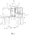
- FIG. 2 schematically represents a simplified top view in the direction of arrow II in FIGS. 1 and 3 of a carriage according to the invention.
- Figure 3 schematically shows a rear view in the direction of the arrows III of Figures 1 and 2 of a carriage according to the invention.
- Figures 4 and 5 show load diagrams characteristic of a carriage according to the invention.
- Figures 6 to 8 schematically represent the steps of a method of boarding a trolley according to the invention at the rear of a carrier vehicle.
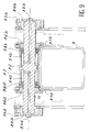
- FIG. 9 schematically shows in section a partial axial view of a telescopic arm of the industrial truck according to the invention.
- FIG. 10 represents a view in partial axial section of another carriage according to the invention.
- a trolley according to the invention comprises a chassis 1 having a U-shaped configuration opening towards the front, a station line 2, a powertrain 3 and lifting means 4.
- a branch 1a of the chassis carries a front wheel 5 while the other branch 1b carries the other front wheel 6.
- the rear steering wheel 7 is mounted substantially in the middle of the main body of the chassis.
- the rear steering wheel 7 is controlled by a steering wheel 8 located in the driving position 2 which also includes all the control members of the lifting means 4.
- the powertrain 3 is preferably a group comprising a heat engine driving a hydraulic pump, the necessary distribution and control members being grouped with the powertrain 3 and controlled directly from the driving position 2.
- the lifting means 4 comprise a telescopic arm 9 mounted to pivot about a substantially horizontal axis 10 located at the rear of the chassis 1 substantially above the rear steering wheel 7.
- the control and driving position is located on one side of the truck, the powertrain 3 is located on the side opposite the control and driving position, and the telescopic arm 9 in its lowered and retracted position corresponding to the transport of a load passes between the driving position 2 and the powertrain 3.
- This arrangement thus provides excellent visibility on the load and on the lifting means 4, unlike the arrangement of the prior art where the retractable mast obstructed the visibility of the operator.
- the telescopic arm 9 carries at its end remote from the pivot axis 10 a gripping member 11 which can be pivotally pivoted about a horizontal axis 12 under the action of an actuation cylinder not shown and of a type known per se .
- the gripping member 11 is preferably shaped like an apron supporting forks 13a, 13b.
- the forks 13a, 13b can start from the lowered and retracted position of the telescopic arm 9 corresponding to the transport of a load and shown in solid lines, to pass to other horizontal or inclined positions in a direction of digging or a direction of dumping. shown in dotted lines.
- the telescopic arm 9 is extensible under the action of an internal cylinder not shown and pivots under the action of a lifting cylinder 14 disposed laterally relative to the arm and fixed to a bracket fixed to the beam of the telescopic arm 9.
- the trolley according to the invention is advantageously fitted with a compensating cylinder, capable of holding the forks 13a, 13b horizontal during the transport of the load in the case of a moving the truck over rough terrain.
- the lifting cylinder 14 and the compensation cylinder 15 are mounted on either side of the beam of the telescopic arm 9, in a position which does not interfere with the visibility of the driver when the telescopic arm 9 is in position transport, fully lowered and retracted.
- all of the lifting means 4 can be moved transversely by a predetermined distance d so as to allow precise adjustment of the positioning of the lifting means when gripping the load.
- the lifting means 4 comprising the telescopic arm 9 can be displaced over the stroke d according to a movement controlled and preferably controlled hydraulically under the action of translation means arranged in the vicinity of the pivot axis 10.
- the hydraulic actuation means comprise at least one hydraulic cylinder, the actuation direction of which is substantially parallel to the pivot axis 10.
- a trolley according to the invention presents a stability diagram without a crutch corresponding to the lifting of a load of 9000 N at a distance of 1 meter in front of the front wheels: this gives performances equivalent to or better than those of on-board carriages of the prior art.
- the carriages according to the invention have a range at the front of the wheels significantly greater than the carts of the prior art.
- FIG. 5 represents a stability diagram with crutch further improved compared to the stability diagram without crutch of FIG. 4 and compared with the characteristics of the on-board carriages of the prior art, in the case where a carriage is fitted according to the invention of retractable stabilizers 16 capable of coming to bear on the ground in front of the point of contact P of a front wheel 5 with the ground.
- the retractable stabilizers 16 capable of coming to bear on the ground in front of the points of contact of the front wheels 5 with the ground are fixed to the chassis 1 of the trolley according to the invention in a manner known per se for the fixing of stabilizers on the on-board carriages of the prior art and controlled analogously by an actuating cylinder exerting a substantially vertical thrust.
- a method of loading a trolley according to the invention and securing to a carrier vehicle comprises the steps described below.
- the telescopic arm is lengthened by a length of the order of 20 cm, so as to thread the forks 13a, 13b in sheaths 20 provided for this purpose and secured to the carrier vehicle under the platform. the latter preferably by quick-attach attachment means of a type known per se.
- supports 21 are arranged in a predetermined position allowing the forks 13a, 13b and the slightly extended telescopic arm 9 to pass between the supports 21.
- the telescopic arm 9 is completely retracted, which has the effect of resting the chassis 2 on the support 21.
- the rear steering wheel 7 is preferably turned completely to the left or completely to the right, so as to limit the protrusion of the carriage towards the rear of the vehicle.
- the carriage then rests under the effect of its own weight on the support 21 on which it is applied by the telescopic arm in the fully retracted position: the equilibrium position of the loading of the machine according to the invention on board the rear of the carrier vehicle is perfectly stable and allows transport over long distances.
- This locking means can for example comprise two lateral locks controlled directly by means of a lever arranged in the station 2 for driving and controlling the carriage.
- These lateral locks can be mechanical or hydraulically controlled, or electrically controlled locks.
- the locking means is controlled by stopping the motor of the carriage or the interruption of electrical energy of the carriage, or the interruption of hydraulic energy of the carriage.
- the powertrain 3 can advantageously be constituted by an electric group operating on battery in the case of applications prohibiting the use of heat engines.
- a piston 30 secured to the pivot axis 10 of the telescopic arm is shown schematically by its main beam 9.
- the piston 30 delimits two chambers 31a and 31b to inside a jacket 32.
- a first bore 33a made substantially coaxially with the pivot axis 10 and a second bore 33b made substantially coaxially with the pivot axis 10 allow the feeding of each chamber 31a or 31b respectively hydraulic fluid.
- the axis 10 is mounted integral with the chassis 1 by means of two mounting parts 34a, 34b assembled to the chassis 1 by screwing, for example of non-protruding screws 35a, 35b, or by any other means allowing the installation of the pivot axis 10 and the passage of the piston 30 through an orifice of diameter provided for this purpose.
- the jacket 32 is closed at its ends by two closing rings 38a, 38b carrying suitable seals, the rings 38a, 38b being fixed in a manner known per se by screwing or equivalent means.
- the structure thus described has a double rod cylinder conformation, in which the piston 30 is fixed and the jacket 32 moves in a first direction when the chamber 31a is put under hydraulic pressure and in a second direction opposite to said first direction when the chamber 31b is put under hydraulic pressure.
- a person skilled in the art can thus easily determine a transverse displacement stroke d as a function of the internal dimensions of the jacket 32 and the width of the piston 30 remaining stationary relative to the pivot axis 10 and relative to the chassis 1 of the forklift.
- each support sleeve 36a or 36b is integral with a bracket 37a or 37b which is itself connected to the main beam of the telescopic lifting arm of the trolley according to the invention.
- the invention makes it possible to carry out a lateral movement in a simple manner which does not hamper the pivoting of the telescopic arm, the lateral displacement means simultaneously allowing the pivoting of the telescopic arm around the substantially horizontal axis 10.
- a piston 40 is integral with the pivot axis 10 of the telescopic arm shown diagrammatically by its main beam 9.
- the piston 40 delimits two chambers 41a and 41b at inside a jacket 42.
- two supply or discharge orifices for hydraulic fluids 43a are produced, 43b directly in the jacket 42.
- Such tapped orifices 43a, 43b for supplying hydraulic fluid are of a type known per se and do not require a more detailed description.
- the axis 10 is mounted integral with the chassis 1 by means of two mounting parts 44a, 44b assembled to the chassis 1 for example by screwing, of non-protruding screws 45a, 45b, or by any other means allowing the installation of the pivot axis 10 and the passage of the piston 40 through an orifice of diameter provided for this purpose.
- the jacket 42 is closed at its ends by two closing rings 48a, 48b carrying suitable seals, the rings 48a, 48b being fixed in a manner known per se by screwing or equivalent means.
- the structure thus described has a double rod cylinder conformation, in which the piston 40 is fixed and the jacket 42 moves in a first direction when the chamber 41a is pressurized hydraulic and in a second direction opposite to said first direction when the chamber 41b is put under hydraulic pressure.
- a person skilled in the art can thus easily determine a transverse displacement stroke d as a function of the internal dimensions of the jacket 42 and the width of the piston 40 remaining stationary relative to the pivot axis 10 and relative to the chassis 1 of the forklift.
- each support sleeve 46a or 46b is integral with a bracket 47a or 47b which is itself connected to the main beam of the telescopic lifting arm of the trolley according to the invention.
- the invention makes it possible to carry out a lateral movement in a simple manner which does not hamper the pivoting of the telescopic arm, the lateral displacement means simultaneously allowing the pivoting of the telescopic arm around the substantially horizontal axis 10.
Landscapes
- Engineering & Computer Science (AREA)
- Transportation (AREA)
- Structural Engineering (AREA)
- Civil Engineering (AREA)
- Life Sciences & Earth Sciences (AREA)
- Geology (AREA)
- Mechanical Engineering (AREA)
- Forklifts And Lifting Vehicles (AREA)
- Handcart (AREA)
Abstract
Description
- L'invention est relative à un chariot de manutention motorisé, notamment du genre apte à être embarqué à l'arrière d'un véhicule porteur.
- On connaît des chariots aptes à être embarqués sur un véhicule porteur tel qu'un camion, pouvant être utilisés au chargement et au déchargement du camion et ensuite être fixés à l'arrière de celui-ci pour être ainsi transportés. Ce genre de chariot est généralement de réalisation peu encombrante, de manière à dépasser du camion d'une faible distance, son châssis étant réalisé de manière que les roues avant soient voisines de l'extrémité avant de sa fourche de chargement.
- A cet effet, les chariots de manutention motorisés du type précité comportent généralement un châssis présentant une conformation en U ouvert vers l'avant, équipé de deux roues avant et d'une roue arrière directrice, de sorte que les moyens de levage s'étendent ainsi dans leur position la plus rétractée entre les branches latérales du châssis en U.
- Une contrainte générale pour la conception des chariots embarqués sur camion est que ces chariots doivent être aussi légers que possible pour ne pas diminuer notablement la charge utile du camion. C'est la raison pour laquelle les chariots embarqués sont généralement dépourvus de contrepoids et conçus de manière que la charge soit disposée entre les bras de roues à l'arrière des roues avant du chariot en position de transport. Cependant, il est nécessaire pour pouvoir déposer ou prendre une charge sur le plateau du camion dans le cas où les roues avant ne peuvent pas passer sous ledit plateau, de prévoir des dispositifs annexes pour avancer les fourches de chargement en avant des roues avant : dans cette position statique de chargement, la charge pouvant être levée par un chariot embarqué est sensiblement égale au poids total à vide du chariot.
- Pour satisfaire aux contraintes précitées, les chariots embarqués de type connu sont tous réalisés sous forme de chariot à mât vertical à double effet : ce mât vertical à double effet permet la manutention et le transport et facilite également le chargement du chariot à l'arrière du camion selon une technique connues par exemple d'après le document FR 2 298 454.
- Les dispositifs annexes connus pour déplacer les fourches à l'avant des roues avant dans le cas d'une prise de charge en avant des roues avant sont du type à fourches télescopiques, à extenseur de fourche, ou à mât rétractable.
- Dans le cas des fourches télescopiques, chaque fourche télescopique présente un fourreau coulissant sur un support guidé par des glissières ou des galets et entraîné par un vérin de manière synchronisée avec le déploiement de l'autre fourche. Cette disposition présente l'inconvénient selon lequel les fourches télescopiques sont soumises à une usure rapide par frottement au contact du sol et nécessite de maintenir les fourches parfaitement horizontales lorsqu'elles sont en position déployée, car la charge se trouvant éloignée du dosseret de charge et du tablier du mât, est susceptible de glisser brusquement jusqu'au dosseret de charge et de provoquer ainsi des accidents indésirables. En outre, cette disposition entraîne des coûts de fabrication élevés et des coûts d'entretien importants pour une fiabilité de fonctionnement relativement faible.
- Dans le système à extenseur de fourches, une structure déformable à ciseaux relie le mât vertical et le tablier supportant les fourches, en déplaçant ainsi les fourches horizontalement vers l'avant lors de la déformation de la structure à ciseaux. Ce système présente d'une part l'inconvenient d'augmenter le dépassement total du chariot à l'arrière du camion, d'une distance correspondant à la longueur de la structure déformable à ciseaux en position repliée, ce qui augmente la longueur de l'ensemble total roulant comprenant le véhicule porteur et le chariot embarqué, et présente d'autre part l'inconvénient de diminuer la charge utile du véhicule porteur correspondant du poids supplémentaire ajouté par la présence de cette structure déformable à ciseaux. En outre, du fait que le tablier supportant les fourches est écarté du mât en position rentrée, les fourches avant sont déportées du mât de la valeur correspondant à cet écartement, ce qui diminue la capacité de transport de charge du chariot ; tandis qu'en position de chargement statique sur place, la charge utile du chariot est réduite en raison du déplacement du centre de gravité résultant du poids supplémentaire de la structure déformable à ciseaux, poids appliqué en avant des roues avant.
- Dans les dispositifs à mât rétractable, le mât est monté sur une structure qui coulisse à l'intérieur du châssis du chariot. Cette disposition présente les mêmes inconvénients que le système extenseur de fourches en raison du fait que le déplacement vers l'avant de l'ensemble comportant le mât et sa structure porteuse entraîne un déplacement important vers l'avant du centre de gravité du chariot, déplacement entraînant une réduction notable de la capacité de transport de charge et de la stabilité en chargement statique sur place.
- De la manière générale, tous les chariots aptes à être embarqués sur camion de l'art antérieur, c'est-à-dire des chariots à mât vertical à double effet, présentent l'inconvénient selon lequel le mât disposé à l'avant du conducteur obstrue le champ de visibilité sur la charge et sur la fourche située à l'opposé du poste de conduite. Ces chariots embarqués de l'art antérieur présentent genéralement une faible garde au sol et ne sont pas aptes à circuler sur des terrains accidentés.
- Il est connu, dans ce domaine des chariots à mât vertical qui n'est pas visé par la présente invention, de déplacer les fourches porteuses latéralement pour les positionner en correspondance avec les charges à manutentionner. En particulier, on peut réaliser le deplacement latéral des fourches à l'aide d'un tablier intermédiaire portant les fourches et se deplaçant latéralement par rapport à un tablier principal. Le déplacement latéral de l'ensemble de la structure de levage comprenant un mât vertical portant un ou plusieurs tabliers peut également être réalisé par rapport au châssis porteur par des moyens appropriés.
- Dans cette technique connue, la mise en oeuvre du déplacement latéral des fourches exige de mettre en place des tabliers intermédiaires ou structures porteuses intermédiaires importantes qui renchérissent le coût du chariot élévateur et en particulier augmentent son poids total en charge, de sorte que la charge utile du chariot est diminuée à poids total en charge constant, et de sorte que le coût de fabrication du chariot est augmenté de manière notable.
- L'invention a pour but de remédier aux inconvénients précités de l'art antérieur, en créant un nouveau chariot de manutention motorisé apte à être embarqué à l'arrière d'un véhicule porteur de manière simple et rapide.
- L'invention a également pour but d'appliquer le principe du déplacement latéral de la structure porteuse au chariot à bras télescopique, sans augmentation notable d'organe mécanique, tout en permettant une exploitation présentant les mêmes performances que celles de l'art antérieur.
- L'invention a pour objet un chariot de manutention motorisé, apte à être embarqué à l'arrière d'un véhicule porteur, du genre comportant un châssis présentant une conformation en U, équipé de deux roues avant et d'une roue arrière directrice, un poste de conduite et des moyens de levage, caractérisé en ce que les moyens de levage comportent un bras télescopique monté à pivotement sous l'action d'un vérin de levage autour d'un axe sensiblement horizontal situé à l'arrière du châssis sensiblement au-dessus de ladite roue arrière directrice.
- Selon d'autres caractéristiques de l'invention :
- le poste de conduite est situé sur un côté du chariot, le groupe motopropulseur est situé du côté opposé au poste de conduite et le bras télescopique dans sa position abaissée et rétractée correspondant au transport d'une charge passe entre le poste de conduite et le groupe motopropulseur.
- le bras télescopique porte à son extrémité éloignée de l'axe de pivotement un organe de préhension orientable à pivotement autour d'un axe horizontal sous l'action d'un vérin d'actionnement.
- le bras télescopiques porte à son extrémité éloignée de l'axe de pivotement un tablier supportant des fourches.
- le bras télescopique équipé d'un tablier supportant des fourches est soumis à l'action d'un vérin de compensation, de manière à maintenir les fourches horizontales.
- le châssis porte des stabilisateurs rétractables aptes à venir en appui sur le sol en avant des points de contact des roues avant avec le sol.
- le vérin de levage et le vérin de compensation sont montés de part et d'autre de la poutre du bras télescopique.
- le chariot comporte un moyen de verrouillage du chariot embarqué sur le véhicule porteur avec un support solidaire du véhicule porteur.
- ledit moyen de verrouillage est commandé directement à partir du poste de conduite du chariot.
- le moyen de verrouillage est commandé sur arrêt du moteur du chariot.
- L'invention a également pour objet un chariot de manutention motorisé, à bras télescopique, comprenant un châssis monté sur une pluralité de roues dont l'une au moins est motrice, ledit châssis portant un groupe motopropulseur, une cabine et des moyens de levage disposés entre le groupe motopropulseur et la cabine, lesdits moyens de levage comprenant ledit bras télescopique monté à pivotement autour d'un axe sensiblement horizontal, caractérisé en ce que l'ensemble des moyens de levage comprenant le bras télescopique est déplaçable transversalement, de manière à permettre un réglage précis sur une distance prédéterminée du positionnement des moyens de levage en vue de la préhension de la charge.
- Selon d'autres caractéristiques de l'invention :
- le bras télescopique est déplaçable transversalement sur son axe de pivotement sous l'action de moyens d'actionnement disposés au voisinage dudit axe de pivotement,
- lesdits moyens d'actionnement sont des moyens d'actionnement hydraulique comportant au moins un vérin hydraulique dont la direction d'actionnement est sensiblement parallèle à l'axe de pivotement du bras télescopique,
- les moyens d'actionnement sont pratiquement coaxiaux à l'axe de pivotement du bras télescopique,
- les moyens d'actionnement sont à double effet,
- les moyens d'actionnement sont des moyens hydrauliques alimentés par des orifices sensiblement parallèles ou coaxiaux à l'axe de pivotement,
- les moyens d'actionnement sont des moyens hydrauliques alimentés par des orifices sensiblement orthogonaux à l'axe de pivotement.
- L'invention sera mieux comprise grâce à la description qui va suivre donnée à titre d'exemple non limitatif en référence aux dessins annexés dans lesquels :
- La figure 1 représente schématiquement une vue en élévation latérale selon la direction de la flèche I des figures 2 et 3 d'un chariot selon l'invention.
- La figure 2 représente schématiquement une vue simplifiée de dessus dans le sens de la flèche II des figures 1 et 3 d'un chariot selon l'invention.
- La figure 3 représente schématiquement une vue arrière dans le sens de la direction des flèches III des figures 1 et 2 d'un chariot selon l'invention.
- Les figures 4 et 5 représentent des diagrammes de charge caractéristiques d'un chariot selon l'invention.
- Les figures 6 à 8 représentent schématiquement les étapes d'un procédé d'embarquement d'un chariot selon l'invention à l'arrière d'un véhicule porteur.
- La figure 9 représente schématiquement en coupe une vue partielle axiale d'un bras télescopique de chariot de manutention selon l'invention.
- La figure 10 représente une vue en coupe axiale partielle d'un autre chariot selon l'invention.
- En référence aux figures 1 à 3, dans lesquelles les éléments identiques ou fonctionnellement équivalents sont repérés par des chiffres de référence identiques, un chariot selon l'invention comporte un châssis 1 présentant une conformation en U s'ouvrant vers l'avant, un poste de conduite 2, un groupe motopropulseur 3 et des moyens de levage 4.
- Une branche 1a du châssis porte une roue avant 5 tandis que l'autre branche 1b porte l'autre roue avant 6. La roue arrière 7 directrice est montée sensiblement au milieu du corps principal du châssis. La roue arrière directrice 7 est commandée par un volant 8 situé dans le poste de conduite 2 qui comporte également tous les organes de commande des moyens de levage 4.
- Le groupe motopropulseur 3 est de préférence un groupe comportant un moteur thermique entraînant une pompe hydraulique, les organes de distribution et de commande nécessaires étant regroupés avec le groupe motopropulseur 3 et commandés directement depuis le poste de conduite 2.
- Selon l'invention, les moyens de levage 4 comportent un bras télescopique 9 monté à pivotement autour d'un axe 10 sensiblement horizontal situé à l'arrière du châssis 1 sensiblement au dessus de la roue arrière directrice 7.
- Le poste de commande et de conduite est situé sur un côté du chariot, le groupe motopropulseur 3 est situé du côte opposé au poste de commande et de conduite, et le bras télescopique 9 dans sa position abaissée et rétractée correspondant au transport d'une charge passe entre le poste de conduite 2 et le groupe motopropulseur 3.
- Cette disposition fournit ainsi une excellente visibilité sur la charge et sur les moyens de levage 4, contrairement à la disposition de l'art antérieur où le mât rétractable obstruait la visibilité de l'opérateur.
- Le bras télescopique 9 porte à son extrémité éloignée de l'axe de pivotement 10 un organe de préhension 11 orientable à pivotement autour d'un axe horizontal 12 sous l'action d'un vérin d'actionnement non représenté et de type connu en soi.
- L'organe de préhension 11 est de préférence conformé en tablier supportant des fourches 13a, 13b. Les fourches 13a, 13b peuvent partir de la position abaissée et rétractée du bras télescopique 9 correspondant au transport d'une charge et représentée en traits pleins, pour passer à d'autres positions horizontales ou inclinées dans un sens de cavage ou un sens de déversement représentées en traits pointillés.
- Le bras télescopique 9 est extensible sous l'action d'un vérin intérieur non représenté et pivote sous l'action d'un vérin de levage 14 disposé latéralement par rapport au bras et fixé à une équerre solidaire de la poutre du bras télescopique 9.
- Dans le cas d'un transport de charge sur terrain accidenté, on équipe avantageusement le chariot selon l'invention d'un vérin de compensation, apte à maintenir les fourches 13a, 13b horizontales lors du transport de la charge dans le cas d'un déplacement du chariot sur terrain accidenté. De préférence, le vérin de levage 14 et le vérin de compensation 15 sont montés de part et d'autre de la poutre du bras télescopique 9, dans une position n'interférant pas avec la visibilité du conducteur lorsque le bras télescopique 9 est en position de transport, entièrement abaissé et rétracté.
- Avantageusement, l'ensemble des moyens de levage 4 est déplaçable transversalement d'une distance prédéterminée d de manière à permettre un réglage précis du positionnement des moyens de levage lors de la préhension de la charge.
- Ainsi, les moyens de levage 4 comprenant le bras télescopique 9 sont déplaçable sur la course d selon un mouvement commandé et contrôlé de préférence hydrauliquement sous l'action de moyens de translation disposés au voisinage de l'axe de pivotement 10.
- De préférence, les moyens d'actionnement hydrauliques comportent au moins un vérin hydraulique, dont la direction d'actionnement est sensiblement parallèle à l'axe de pivotement 10.
- En référence à la figure 4, un chariot selon l'invention présente un diagramme de stabilité sans béquille correspondant à la levée d'une charge de 9000 N à une distance de 1 mètre en avant des roues avant : on obtient ainsi des performances équivalentes à ou meilleures que celles des chariots embarqués de l'art antérieur. En particulier, les chariots selon l'invention ont une portée à l'avant des roues notablement supérieure aux chariots de l'art antérieur.
- La figure 5 représente un diagramme de stabilité avec béquille encore amélioré par rapport au diagramme de stabilité sans béquille de la figure 4 et par rapport aux caractéristiques des chariots embarqués de l'art antérieur, dans le cas où l'on équipe un chariot selon l'invention de stabilisateurs 16 rétractables aptes à venir en appui sur le sol en avant du point de contact P d'une roue avant 5 avec le sol.
- Les stabilisateurs 16 rétractables aptes à venir en appui sur le sol en avant des points de contact des roues avant 5 avec le sol sont fixés sur le châssis 1 du chariot selon l'invention selon une manière connue en soi pour la fixation de stabilisateurs sur les chariots embarqués de l'art antérieur et commandés de manière analogue par un vérin d'actionnement exerçant une poussée sensiblement verticale.
- En référence aux figures 6 à 8, un procédé de chargement d'un chariot selon l'invention et de solidarisation à un véhicule porteur comporte les étapes décrites ci-après.
- En référence à la figure 6, on allonge le bras télescopique d'une longueur de l'ordre de 20 cm, de manière à enfiler les fourches 13a, 13b dans des fourreaux 20 prévus à cet effet et solidarisés au véhicule porteur sous le plateau de celui-ci de préférence par des moyens d'accrochage à fixation rapide de type connus en soi. A l'arrière des fourreaux 20, des supports 21 sont disposés dans une position prédéterminée permettant le passage des fourches 13a, 13b et du bras télescopique 9 légèrement étendu entre les supports 21.
- Après avoir enfilé les fourches dans les fourreaux 20, on effectue un mouvement combiné de montée et de pivotement du chariot autour du bras télescopique 9 jusqu'à la position représentée à la figure 7 dans laquelle le châssis 1 est entièrement soulevé du sol et incliné légèrement vers l'avant d'un angle compris entre 10 et 15 degrés d'angles sexagésimaux.
- A partir de la position de la figure 7, on rétracte complètement le bras télescopique 9, ce qui a pour effet de reposer le châssis 2 sur le support 21. On braque de préférence la roue directrice arrière 7 complètement à gauche ou complètement à droite, de manière à limiter le dépassement du chariot vers l'arrière du véhicule.
- Le chariot repose alors sous l'effet de son propre poids sur le support 21 sur lequel il est appliqué par le bras télescopique en position complètement rétractée : la position d'équilibre du chargement de la machine selon l'invention embarquée à l'arrière du véhicule porteur est parfaitement stable et permet le transport sur de longues distances.
- Avantageusement, on prévoit un moyen de verrouillage complémentaire du chariot embarqué sur le véhicule porteur avec le support 21 solidaire du véhicule porteur. Ce moyen de verrouillage peut par exemple comporter deux verrous latéraux commandés directement au moyen d'une manette disposée dans le poste 2 de conduite et de commande du chariot. Ces verrous latéraux peuvent être des verrous mécaniques ou à commande hydraulique, ou encore à commande électrique. Dans une variante préférée, le moyen de verrouillage est commandé par l'arrêt du moteur du chariot ou l'interruption d'énergie électrique du chariot, ou l'interruption d'énergie hydraulique du chariot.
- L'invention décrite en référence à des modes de réalisation particuliers n'y est nullement limitée mais couvre au contraire toute modification de forme et toute variante de réalisation dans le cadre de l'esprit de l'invention : ainsi, le groupe motopropulseur 3 peut avantageusement être constitué par un groupe électrique fonctionnant sur batterie dans le cas d'applications interdisant l'emploi de moteurs thermiques.
- En référence à la figure 9, dans un premier mode de réalisation de l'invention, un piston 30 solidaire de l'axe de pivotement 10 du bras télescopique est schématisé par sa poutre principale 9. Le piston 30 délimite deux chambres 31a et 31b à l'intérieur d'une chemise 32. Un premier perçage 33a pratiqué sensiblement coaxialement à l'axe de pivotement 10 et un deuxième perçage 33b pratiqué sensiblement coaxialement à l'axe de pivotement 10 permettent l'alimentation respectivement de chaque chambre 31a ou 31b en fluide hydraulique.
- L'axe 10 est monté solidaire du châssis 1 par l'intermédiaire de deux pièces de montage 34a, 34b assemblées au châssis 1 par vissage, par exemple de vis non dépassantes 35a, 35b, ou par tout autre moyen permettant la mise en place de l'axe de pivotement 10 et le passage du piston 30 par un orifice de diamètre prévu à cet effet.
- La chemise 32 est obturée à ses extrémités par deux bagues de fermeture 38a, 38b portant des joints d'étanchéité appropriés, les bagues 38a, 38b étant fixées de manière connue en soi par vissage ou moyen équivalent.
- La structure ainsi décrite présente une conformation en vérin à double tige, dans lequel le piston 30 est fixe et la chemise 32 se déplace dans un premier sens lorsque la chambre 31a est mise sous pression hydraulique et dans un deuxième sens opposé audit premier sens lorsque la chambre 31b est mise sous pression hydraulique.
- L'homme du métier peut ainsi déterminer sans difficulté une course de déplacement transversal d en fonction des dimensions internes de la chemise 32 et de la largeur du piston 30 restant immobile par rapport à l'axe de pivotement 10 et par rapport au châssis 1 du chariot élévateur.
- Dans le déplacement imposé par la pression hydraulique introduite dans l'une ou l'autre chambre 31a ou 31b, la chemise 32 appuie par l'intermédiaire de l'une ou l'autre bague de fermeture 38b ou 38a sur des douilles d'appui 36b ou 36a. Chaque douille d'appui 36a ou 36b est solidaire d'une équerre 37a ou 37b qui est elle-même reliée à la poutre principale du bras élévateur télescopique du chariot selon l'invention.
- Ainsi, l'invention permet de réaliser de manière simple un déplacement latéral qui n'entrave pas le pivotement du bras télescopique, les moyens de déplacement latéral permettant simultanément le pivotement du bras télescopique autour de l'axe sensiblement horizontal 10.
- En référence à la figure 10, dans un autre mode de réalisation de l'invention, un piston 40 est solidaire de l'axe de pivotement 10 du bras télescopique schématisé par sa poutre principale 9. Le piston 40 délimite deux chambres 41a et 41b à l'intérieur d'une chemise 42. Pour éviter le perçage des orifices de diamètre réduit et de longueur importante 33a, 33b du mode de réalisation de la figure 9, on réalise deux orifices d'alimentation ou d'évacuation de fluides hydrauliques 43a, 43b directement dans la chemise 42. De tels orifices taraudés 43a, 43b d'alimentation en fluide hydraulique sont de type connu en soi et ne nécessitent pas de description plus détaillée.
- L'axe 10 est monté solidaire du châssis 1 par l'intermédiaire de deux pièces de montage 44a, 44b assemblées au châssis 1 par exemple par vissage, de vis non dépassantes 45a, 45b, ou par tout autre moyen permettant la mise en place de l'axe de pivotement 10 et le passage du piston 40 par un orifice de diamètre prévu à cet effet.
- La chemise 42 est obturée à ses extrémités par deux bagues de fermeture 48a, 48b portant des joints d'étanchéité appropriés, les bagues 48a, 48b étant fixées de manière connue en soi par vissage ou moyen équivalent.
- La structure ainsi décrite présente une conformation en vérin à double tige, dans lequel le piston 40 est fixe et la chemise 42 se déplace dans un premier sens lorsque la chambre 41a est mise sous pression hydraulique et dans un deuxième sens opposé audit premier sens lorsque la chambre 41b est mise sous pression hydraulique.
- L'homme du métier peut ainsi déterminer sans difficulté une course de déplacement transversal d en fonction des dimensions internes de la chemise 42 et de la largeur du piston 40 restant immobile par rapport à l'axe de pivotement 10 et par rapport au châssis 1 du chariot élévateur.
- Dans le déplacement imposé par la pression hydraulique introduite dans l'une ou l'autre chambre 41a ou 41b, la chemise 42 appuie par l'intermédiaire de l'une ou l'autre bague de fermeture 48b ou 48a sur des douilles d'appui 46b ou 46a. Chaque douille d'appui 46a ou 46b est solidaire d'une équerre 47a ou 47b qui est elle-même reliée à la poutre principale du bras élévateur télescopique du chariot selon l'invention.
- Ainsi, l'invention permet de réaliser de manière simple un déplacement latéral qui n'entrave pas le pivotement du bras télescopique, les moyens de déplacement latéral permettant simultanément le pivotement du bras télescopique autour de l'axe sensiblement horizontal 10.
- L'invention bien que décrite en référence à deux modes de réalisation particuliers n'y est nullement limitée, mais couvre au contraire toute modification de forme et toute variante de réalisation dans le cadre et l'esprit de l'invention, notamment toute variante dans lesquelles le pivotement et le déplacement transversal peuvent être assurés coaxialement à l'axe de pivotement 10.
Claims (17)
- Chariot de manutention motorisé (3), apte à être embarqué à l'arrière d'un véhicule porteur, du genre comportant un châssis (1) présentant une conformation en U, équipé de deux roues avant et d'une roue arrière directrice, un poste de conduite (2) et des moyens de levage (4), caractérisé en ce que les moyens de levage (4) comportent un bras télescopique (9) monté à pivotement sous l'action d'un vérin de levage (14) autour d'un axe (10) sensiblement horizontal situé à l'arrière du châssis (1) sensiblement au-dessus de ladite roue arrière directrice (7).
- Chariot selon la revendication 1, caractérisé en ce que le poste de conduite (2) est situé sur un côté du chariot, le groupe motopropulseur (3) est situé du côté opposé au poste de conduite (2) et le bras télescopique (9) dans sa position abaissée et rétractée correspondant au transport d'une charge passe entre le poste de conduite (2) et le groupe motopropulseur (3).
- Chariot selon la revendication 1 ou la revendication 2, caractérisé en ce que le bras télescopique porte à son extrémité éloignée de l'axe de pivotement (10) un organe de préhension (11) orientable à pivotement autour d'un axe horizontal (12) sous l'action d'un vérin d'actionnement.
- Chariot selon l'une des revendications précédentes, caractérisé en ce que le bras télescopique porte à son extrémité éloignée de l'axe de pivotement (10) un tablier (11) supportant des fourches (13a, 13b).
- Chariot selon la revendication 4, caractérisé en ce que le bras télescopique (9) équipé d'un tablier (11) supportant des fourches (13a, 13b) est soumis à l'action d'un vérin (15) de compensation, de manière à maintenir les fourches horizontales (13a, 13b).
- Chariot selon l'une des revendications précédentes, caractérisé en ce que le châssis (1) porte des stabilisateurs (16) rétractables aptes à venir en appui sur le sol en avant des points de contact des roues avant (5, 6) avec le sol.
- Chariot selon la revendication 5, caractérisé en ce que le vérin de levage (14) et le vérin de compensation (15) sont montés de part et d'autre de la poutre du bras télescopique (9).
- Chariot selon l'une des revendications précédentes, caractérisé en ce que le chariot comporte un moyen de verrouillage du chariot embarqué sur le véhicule porteur avec un support (21) solidaire du véhicule porteur.
- Chariot selon la revendication 8, caractérisé en ce que ledit moyen de verrouillage est commandé directement à partir du poste de conduite (2) du chariot.
- Chariot selon la revendication 8 ou la revendication 9, caractérisé en ce que le moyen de verrouillage est commandé sur arrêt du moteur (3) du chariot.
- Chariot de manutention motorisé, à bras télescopique, comprenant un châssis monté sur une pluralité de roues dont l'une au moins est motrice, ledit châssis portant un groupe motopropulseur, une cabine et des moyens de levage disposés entre le groupe motopropulseur et la cabine, lesdits moyens de levage comprenant ledit bras télescopique monté à pivotement autour d'un axe sensiblement horizontal, caractérisé en ce que l'ensemble des moyens de levage (4) comprenant le bras télescopique (9) est déplaçable transversalement, de manière à permettre un réglage précis sur une distance prédéterminé (d) du positionnement des moyens de levage en vue de la préhension de la charge.
- Chariot selon la revendication 11, caractérisé en ce que le bras télescopique (9) est déplaçable transversalement sur son axe (10) de pivotement sous l'action de moyens d'actionnement disposés au voisinage dudit axe (10) de pivotement.
- Chariot selon la revendication 12, caractérisé en ce que lesdits moyens d'actionnement sont des moyens d'actionnement hydraulique comportant au moins un vérin hydraulique dont la direction d'actionnement est sensiblement parallèle à l'axe (10) de pivotement du bras télescopique (9).
- Chariot selon la revendication 12 ou la revendication 13, caractérisé en ce que les moyens d'actionnement sont pratiquement coaxiaux à l'axe (10) de pivotement du bras télescopique (9).
- Chariot selon l'une quelconque des revendications 12 à 14, caractérisé en ce que les moyens d'actionnement sont à double effet.
- Chariot selon l'une quelconque des revendications 12 à 15, caractérisé en ce que les moyens d'actionnement sont des moyens hydrauliques alimentés par des orifices sensiblement parallèles ou coaxiaux à l'axe de pivotement (10).
- Chariot selon l'une quelconque des revendications 12 à 15, caractérisé en ce que les moyens d'actionnement sont des moyens hydrauliques alimentés par des orifices sensiblement orthogonaux à l'axe de pivotement (10).
Applications Claiming Priority (4)
| Application Number | Priority Date | Filing Date | Title |
|---|---|---|---|
| FR9410953A FR2724374B1 (fr) | 1994-09-14 | 1994-09-14 | Chariot de manutention motorise apte a etre embarque a l'arriere d'un vehicule porteur |
| FR9410953 | 1994-09-14 | ||
| FR9500033A FR2728884A1 (fr) | 1995-01-04 | 1995-01-04 | Chariot de manutention motorise a bras telescopique |
| FR9500033 | 1995-01-04 |
Publications (3)
| Publication Number | Publication Date |
|---|---|
| EP0701963A1 true EP0701963A1 (fr) | 1996-03-20 |
| EP0701963B1 EP0701963B1 (fr) | 1998-02-04 |
| EP0701963B2 EP0701963B2 (fr) | 2004-08-18 |
Family
ID=26231398
Family Applications (1)
| Application Number | Title | Priority Date | Filing Date |
|---|---|---|---|
| EP95402069A Expired - Lifetime EP0701963B2 (fr) | 1994-09-14 | 1995-09-13 | Chariot de manutention motorisé à bras téléscopique |
Country Status (4)
| Country | Link |
|---|---|
| US (1) | US5813821A (fr) |
| EP (1) | EP0701963B2 (fr) |
| CA (1) | CA2158232C (fr) |
| DE (2) | DE701963T1 (fr) |
Cited By (6)
| Publication number | Priority date | Publication date | Assignee | Title |
|---|---|---|---|---|
| FR2750970A1 (fr) * | 1996-07-12 | 1998-01-16 | Fdi Sambron | Chariot de manutention comprenant un dispositif de protection du cariste |
| EP0927698A1 (fr) * | 1997-11-04 | 1999-07-07 | Karl Schaeff GmbH & Co. Maschinenfabrik | Appareil de travail sur roues mobile transversalement |
| WO1999054249A1 (fr) * | 1998-04-17 | 1999-10-28 | Liftcon Technologies Limited | Chariot elevateur transportable, a bras de levage telescopique |
| US6293579B1 (en) | 1999-03-08 | 2001-09-25 | Karl Schaeff Gmbh & Co Maschinenfabrik | Mobile rig on wheels with transverse motion |
| EP1348668A1 (fr) | 2002-03-29 | 2003-10-01 | Manitou Bf | Chariot élévateur à portée variable à trois roues |
| WO2015185146A1 (fr) * | 2014-06-05 | 2015-12-10 | Combilift | Dispositif de chargement/déchargement de conteneur |
Families Citing this family (9)
| Publication number | Priority date | Publication date | Assignee | Title |
|---|---|---|---|---|
| DE602004001836T2 (de) * | 2003-11-17 | 2007-03-29 | Moffett Research And Development Ltd., Dundalk | Transportabler Gabelhubwagen |
| US8087868B2 (en) * | 2004-01-13 | 2012-01-03 | Moffett Research And Development Limited | Forklift truck for mounting on the rear of a carrying vehicle with a fork side shifting attachment |
| US8308417B1 (en) | 2008-12-18 | 2012-11-13 | Joseph Verrochi | Method and system for transporting, loading, and unloading various types of goods |
| CN104444969B (zh) * | 2014-11-26 | 2017-10-10 | 王马达 | 保障简易叉车随集装箱运行的吊运及固定设备及使用方法 |
| GB2543317A (en) * | 2015-10-14 | 2017-04-19 | Cargotec Res & Dev Ireland Ltd | A Truck mounted forklift |
| EP3555375B1 (fr) * | 2016-12-16 | 2024-07-31 | Doosan Bobcat North America, Inc. | Chargeuse avec bras de levage télescopiques |
| GB2572356B (en) * | 2018-03-27 | 2022-09-14 | Bamford Excavators Ltd | Load-handling vehicle |
| CN109704237B (zh) * | 2019-01-16 | 2020-09-04 | 安徽宇锋智能科技有限公司 | 一种具有智能判定识别感知功能的agv牵引叉车 |
| US12454209B2 (en) * | 2021-04-29 | 2025-10-28 | Hol-Mac Corporation | Truck carried forklift mounting system |
Citations (9)
| Publication number | Priority date | Publication date | Assignee | Title |
|---|---|---|---|---|
| DE2402704A1 (de) * | 1973-01-26 | 1974-08-01 | Tobias Heinrich Adolph Grether | Gabelstapler |
| FR2298507A1 (fr) * | 1975-01-21 | 1976-08-20 | Kooi Bv | Chariot elevateur a fourche |
| GB1525923A (en) * | 1975-10-09 | 1978-09-27 | Liner Concrete Machinery | Load handling vehicle with load engaging means |
| FR2387185A1 (fr) * | 1977-04-15 | 1978-11-10 | Kaup Gmbh & Co Kg | Dispositif de translation laterale pour elevateur |
| WO1982001363A1 (fr) * | 1980-10-16 | 1982-04-29 | David W Lutz | Chariot de levage et de transport |
| US4826474A (en) * | 1987-12-14 | 1989-05-02 | Butterworth Jetting Systems, Inc. | Forklift apparatus for unloading articles from an elevated surface |
| EP0325064A1 (fr) * | 1987-12-18 | 1989-07-26 | Manitou Bf | Amélioration à la stabilité des chariots élévateurs à bras télescopique |
| US5113969A (en) * | 1991-05-10 | 1992-05-19 | Centre De Recherche Industrielle Du Quebec | Displaceable working platform with extensible boom |
| EP0504527A1 (fr) * | 1991-03-20 | 1992-09-23 | Gcm 600 Limited | Véhicule de manutention de charge |
Family Cites Families (19)
| Publication number | Priority date | Publication date | Assignee | Title |
|---|---|---|---|---|
| US2731162A (en) * | 1953-11-19 | 1956-01-17 | Superior Separator Company | Loader with self-leveling carrier |
| US3243053A (en) * | 1964-11-13 | 1966-03-29 | Deere & Co | Backhoe |
| US3407947A (en) * | 1965-12-22 | 1968-10-29 | Antonio Valla & C S N C | Material-moving device for moving objects |
| US3688929A (en) * | 1970-09-30 | 1972-09-05 | Skagit Corp | Lift truck with rotatable carriage |
| US3754673A (en) * | 1971-12-13 | 1973-08-28 | Clark Equipment Co | Detachable fork for lift trucks |
| US3836025A (en) * | 1973-05-21 | 1974-09-17 | Loed Corp | Material-handling machine |
| JPS5339681B2 (fr) * | 1974-11-14 | 1978-10-23 | ||
| NL160764C (nl) † | 1975-01-21 | 1983-03-16 | Kooi Bv | Vrachtauto met een bijbehorende vorkhefwagen. |
| DE2739537A1 (de) * | 1976-09-03 | 1978-03-09 | Loed Corp | Schwenkgabelanordnung fuer verladeausruestungen |
| US4147263A (en) † | 1977-01-06 | 1979-04-03 | Lull Engineering Company, Inc. | High lift loader with extended transfer |
| CA1164503A (fr) † | 1981-07-14 | 1984-03-27 | Brouwer Turf Equipment Limited | Methode de montage d'un chariot elevateur a fourche sur un vehicule porteur |
| US4674944A (en) * | 1985-12-27 | 1987-06-23 | Kidde, Inc. | Forklift variable reach mechanism |
| US4688982A (en) * | 1986-08-01 | 1987-08-25 | Smart Robert L | Motorized operator unit for manually adjustable fork mechanism |
| US4848010A (en) * | 1987-07-27 | 1989-07-18 | Zimmerman Harold M | Backhoe machine |
| IT212207Z2 (it) † | 1987-07-27 | 1989-07-04 | Merlo Ind Metalmecc | Carrello elevatore a braccio telescopico |
| US4964778A (en) * | 1989-07-27 | 1990-10-23 | Kidde Industries, Inc. | Forklift truck having a telescopic auxiliary boom articulated to a telescopic main boom |
| US4964788A (en) † | 1990-03-21 | 1990-10-23 | Tecumseh Products Company | Hermetic terminal with terminal pin assemblies having fusible links and motor compressor unit including same |
| FR2690895A1 (fr) † | 1992-05-07 | 1993-11-12 | Manitou Bf | Chariot de manutention électrique à bras télescopique. |
| GB2292930B (en) † | 1992-06-30 | 1996-10-02 | Caterpillar Inc | Material handling machine |
-
1995
- 1995-09-13 EP EP95402069A patent/EP0701963B2/fr not_active Expired - Lifetime
- 1995-09-13 DE DE0701963T patent/DE701963T1/de active Pending
- 1995-09-13 CA CA002158232A patent/CA2158232C/fr not_active Expired - Lifetime
- 1995-09-13 DE DE69501578T patent/DE69501578T3/de not_active Expired - Lifetime
- 1995-09-14 US US08/528,300 patent/US5813821A/en not_active Expired - Lifetime
Patent Citations (9)
| Publication number | Priority date | Publication date | Assignee | Title |
|---|---|---|---|---|
| DE2402704A1 (de) * | 1973-01-26 | 1974-08-01 | Tobias Heinrich Adolph Grether | Gabelstapler |
| FR2298507A1 (fr) * | 1975-01-21 | 1976-08-20 | Kooi Bv | Chariot elevateur a fourche |
| GB1525923A (en) * | 1975-10-09 | 1978-09-27 | Liner Concrete Machinery | Load handling vehicle with load engaging means |
| FR2387185A1 (fr) * | 1977-04-15 | 1978-11-10 | Kaup Gmbh & Co Kg | Dispositif de translation laterale pour elevateur |
| WO1982001363A1 (fr) * | 1980-10-16 | 1982-04-29 | David W Lutz | Chariot de levage et de transport |
| US4826474A (en) * | 1987-12-14 | 1989-05-02 | Butterworth Jetting Systems, Inc. | Forklift apparatus for unloading articles from an elevated surface |
| EP0325064A1 (fr) * | 1987-12-18 | 1989-07-26 | Manitou Bf | Amélioration à la stabilité des chariots élévateurs à bras télescopique |
| EP0504527A1 (fr) * | 1991-03-20 | 1992-09-23 | Gcm 600 Limited | Véhicule de manutention de charge |
| US5113969A (en) * | 1991-05-10 | 1992-05-19 | Centre De Recherche Industrielle Du Quebec | Displaceable working platform with extensible boom |
Cited By (9)
| Publication number | Priority date | Publication date | Assignee | Title |
|---|---|---|---|---|
| FR2750970A1 (fr) * | 1996-07-12 | 1998-01-16 | Fdi Sambron | Chariot de manutention comprenant un dispositif de protection du cariste |
| EP0927698A1 (fr) * | 1997-11-04 | 1999-07-07 | Karl Schaeff GmbH & Co. Maschinenfabrik | Appareil de travail sur roues mobile transversalement |
| WO1999054249A1 (fr) * | 1998-04-17 | 1999-10-28 | Liftcon Technologies Limited | Chariot elevateur transportable, a bras de levage telescopique |
| EP0953540A1 (fr) * | 1998-04-17 | 1999-11-03 | Liftcon Technologies Limited | Chariot élévateur transportable avec bras élévateur téléscopique |
| US6641355B1 (en) * | 1998-04-17 | 2003-11-04 | Liftcon Technologies Limited | Transportable lift truck with telescopic lifting arm |
| US6293579B1 (en) | 1999-03-08 | 2001-09-25 | Karl Schaeff Gmbh & Co Maschinenfabrik | Mobile rig on wheels with transverse motion |
| EP1348668A1 (fr) | 2002-03-29 | 2003-10-01 | Manitou Bf | Chariot élévateur à portée variable à trois roues |
| US7121372B2 (en) | 2002-03-29 | 2006-10-17 | Manitou Bf | Lift truck with variable range with at least three wheels |
| WO2015185146A1 (fr) * | 2014-06-05 | 2015-12-10 | Combilift | Dispositif de chargement/déchargement de conteneur |
Also Published As
| Publication number | Publication date |
|---|---|
| DE69501578T3 (de) | 2005-02-03 |
| US5813821A (en) | 1998-09-29 |
| DE69501578T2 (de) | 1998-09-17 |
| DE69501578D1 (de) | 1998-03-12 |
| DE701963T1 (de) | 1996-12-12 |
| CA2158232C (fr) | 2001-08-07 |
| EP0701963B2 (fr) | 2004-08-18 |
| EP0701963B1 (fr) | 1998-02-04 |
| CA2158232A1 (fr) | 1996-03-15 |
Similar Documents
| Publication | Publication Date | Title |
|---|---|---|
| EP0701963B1 (fr) | Chariot de manutention motorisé à bras téléscopique | |
| EP2874827B1 (fr) | Essieu et vehicule comprenant au moins un tel essieu | |
| CA2585850C (fr) | Chariot de manutention a au moins trois roues directrices | |
| EP0905083B1 (fr) | Chariot à mât, apte à être embarqué à l'arrière d'un véhicule porteur | |
| FR2800363A1 (fr) | Chariot elevateur a fourche | |
| FR2598142A1 (fr) | Chariot elevateur a fourche avec un bloc de commande orientable et un ensemble porte-charge mobile en hauteur. | |
| FR2624842A1 (fr) | Amelioration a la stabilite des chariots elevateurs a bras telescopique | |
| FR2607076A1 (fr) | Vehicule, notamment chariot de manutention | |
| EP0490798B1 (fr) | Grue, en particulier pour la manutention | |
| EP0378034B1 (fr) | Dispositif de basculement d'un plateau de chargement | |
| FR2615157A1 (fr) | Tracteur perfectionne notamment pour semi-remorque | |
| FR2496034A1 (fr) | Nouvel appareil de manutention du genre diable | |
| EP0493284A1 (fr) | Actionneur d'articulation pour la mise en oeuvre de tous mouvements rectilignes ou rotatifs | |
| FR2791049A1 (fr) | Porte equipement pour engin de levage, mat d'un engin de levage comprenant un tel porte equipement et engin de levage tel que chariot a fourches pourvu dudit mat | |
| FR2728884A1 (fr) | Chariot de manutention motorise a bras telescopique | |
| FR2724374A1 (fr) | Chariot de manutention motorise apte a etre embarque a l'arriere d'un vehicule porteur | |
| FR2750125A1 (fr) | Chariot elevateur pour preparation de commandes | |
| FR2759998A1 (fr) | Engin porte-outil pour le transport, la manutention et l'execution de travaux avec des outils | |
| FR2867175A1 (fr) | Chariot elevateur comportant au moins un element amortisseur | |
| FR2765865A1 (fr) | Vehicule de manutention de materiaux | |
| FR2987795A1 (fr) | Ensemble de manutention destine a equiper un chassis d'un vehicule, pour la pose, la depose et/ou le bennage et le transport de tout type de conteneur | |
| FR2570655A1 (fr) | Vehicule, notamment chariot de manutention | |
| FR2755681A1 (fr) | Chariot elevateur a dispositif de stabilisateur | |
| FR2730681A1 (fr) | Plateau mobile pour vehicule porte-plateau destine au chargement et au transport d'objets, notamment d'automobiles | |
| FR2698063A1 (fr) | Chariot porte-palettes. |
Legal Events
| Date | Code | Title | Description |
|---|---|---|---|
| PUAI | Public reference made under article 153(3) epc to a published international application that has entered the european phase |
Free format text: ORIGINAL CODE: 0009012 |
|
| AK | Designated contracting states |
Kind code of ref document: A1 Designated state(s): DE FR GB IE IT NL |
|
| 17P | Request for examination filed |
Effective date: 19960418 |
|
| IECL | Ie: translation for ep claims filed | ||
| DET | De: translation of patent claims | ||
| 17Q | First examination report despatched |
Effective date: 19970424 |
|
| GRAG | Despatch of communication of intention to grant |
Free format text: ORIGINAL CODE: EPIDOS AGRA |
|
| GRAG | Despatch of communication of intention to grant |
Free format text: ORIGINAL CODE: EPIDOS AGRA |
|
| GRAH | Despatch of communication of intention to grant a patent |
Free format text: ORIGINAL CODE: EPIDOS IGRA |
|
| GRAH | Despatch of communication of intention to grant a patent |
Free format text: ORIGINAL CODE: EPIDOS IGRA |
|
| GRAA | (expected) grant |
Free format text: ORIGINAL CODE: 0009210 |
|
| AK | Designated contracting states |
Kind code of ref document: B1 Designated state(s): DE FR GB IE IT NL |
|
| PG25 | Lapsed in a contracting state [announced via postgrant information from national office to epo] |
Ref country code: IT Free format text: LAPSE BECAUSE OF FAILURE TO SUBMIT A TRANSLATION OF THE DESCRIPTION OR TO PAY THE FEE WITHIN THE PRE;WARNING: LAPSES OF ITALIAN PATENTS WITH EFFECTIVE DATE BEFORE 2007 MAY HAVE OCCURRED AT ANY TIME BEFORE 2007. THE CORRECT EFFECTIVE DATE MAY BE DIFFERENT FROM THE ONE RECORDED.SCRIBED TIME-LIMIT Effective date: 19980204 |
|
| REF | Corresponds to: |
Ref document number: 69501578 Country of ref document: DE Date of ref document: 19980312 |
|
| GBT | Gb: translation of ep patent filed (gb section 77(6)(a)/1977) |
Effective date: 19980429 |
|
| PLBQ | Unpublished change to opponent data |
Free format text: ORIGINAL CODE: EPIDOS OPPO |
|
| PLBI | Opposition filed |
Free format text: ORIGINAL CODE: 0009260 |
|
| PLBQ | Unpublished change to opponent data |
Free format text: ORIGINAL CODE: EPIDOS OPPO |
|
| PLBI | Opposition filed |
Free format text: ORIGINAL CODE: 0009260 |
|
| 26 | Opposition filed |
Opponent name: TRANSMANUT Effective date: 19981022 |
|
| 26 | Opposition filed |
Opponent name: MOFFETT ENGINEERING LIMITED Effective date: 19981103 Opponent name: TRANSMANUT Effective date: 19981022 |
|
| PLBF | Reply of patent proprietor to notice(s) of opposition |
Free format text: ORIGINAL CODE: EPIDOS OBSO |
|
| NLR1 | Nl: opposition has been filed with the epo |
Opponent name: TRANSMANUT |
|
| NLR1 | Nl: opposition has been filed with the epo |
Opponent name: MOFFETT ENGINEERING LIMITED Opponent name: TRANSMANUT |
|
| PLBF | Reply of patent proprietor to notice(s) of opposition |
Free format text: ORIGINAL CODE: EPIDOS OBSO |
|
| PG25 | Lapsed in a contracting state [announced via postgrant information from national office to epo] |
Ref country code: FR Free format text: LAPSE BECAUSE OF NON-PAYMENT OF DUE FEES Effective date: 19990531 |
|
| REG | Reference to a national code |
Ref country code: FR Ref legal event code: ST |
|
| REG | Reference to a national code |
Ref country code: GB Ref legal event code: IF02 |
|
| PLBO | Opposition rejected |
Free format text: ORIGINAL CODE: EPIDOS REJO |
|
| APAC | Appeal dossier modified |
Free format text: ORIGINAL CODE: EPIDOS NOAPO |
|
| APAC | Appeal dossier modified |
Free format text: ORIGINAL CODE: EPIDOS NOAPO |
|
| APBU | Appeal procedure closed |
Free format text: ORIGINAL CODE: EPIDOSNNOA9O |
|
| PUAH | Patent maintained in amended form |
Free format text: ORIGINAL CODE: 0009272 |
|
| STAA | Information on the status of an ep patent application or granted ep patent |
Free format text: STATUS: PATENT MAINTAINED AS AMENDED |
|
| 27A | Patent maintained in amended form |
Effective date: 20040818 |
|
| AK | Designated contracting states |
Kind code of ref document: B2 Designated state(s): DE FR GB IE IT NL |
|
| NLR2 | Nl: decision of opposition |
Effective date: 20040818 |
|
| GBTA | Gb: translation of amended ep patent filed (gb section 77(6)(b)/1977) | ||
| APAA | Appeal reference recorded |
Free format text: ORIGINAL CODE: EPIDOS REFN |
|
| NLR3 | Nl: receipt of modified translations in the netherlands language after an opposition procedure | ||
| APAH | Appeal reference modified |
Free format text: ORIGINAL CODE: EPIDOSCREFNO |
|
| PLAB | Opposition data, opponent's data or that of the opponent's representative modified |
Free format text: ORIGINAL CODE: 0009299OPPO |
|
| PGFP | Annual fee paid to national office [announced via postgrant information from national office to epo] |
Ref country code: IE Payment date: 20140918 Year of fee payment: 20 Ref country code: DE Payment date: 20140922 Year of fee payment: 20 |
|
| PGFP | Annual fee paid to national office [announced via postgrant information from national office to epo] |
Ref country code: GB Payment date: 20140919 Year of fee payment: 20 |
|
| REG | Reference to a national code |
Ref country code: DE Ref legal event code: R082 Ref document number: 69501578 Country of ref document: DE Representative=s name: BUNGARTZ CHRISTOPHERSEN PARTNERSCHAFT MBB PATE, DE |
|
| PGFP | Annual fee paid to national office [announced via postgrant information from national office to epo] |
Ref country code: NL Payment date: 20140918 Year of fee payment: 20 |
|
| REG | Reference to a national code |
Ref country code: DE Ref legal event code: R071 Ref document number: 69501578 Country of ref document: DE |
|
| REG | Reference to a national code |
Ref country code: NL Ref legal event code: MK Effective date: 20150912 |
|
| REG | Reference to a national code |
Ref country code: GB Ref legal event code: PE20 Expiry date: 20150912 |
|
| PG25 | Lapsed in a contracting state [announced via postgrant information from national office to epo] |
Ref country code: GB Free format text: LAPSE BECAUSE OF EXPIRATION OF PROTECTION Effective date: 20150912 |
|
| REG | Reference to a national code |
Ref country code: IE Ref legal event code: MK9A |
|
| PG25 | Lapsed in a contracting state [announced via postgrant information from national office to epo] |
Ref country code: IE Free format text: LAPSE BECAUSE OF EXPIRATION OF PROTECTION Effective date: 20150913 |